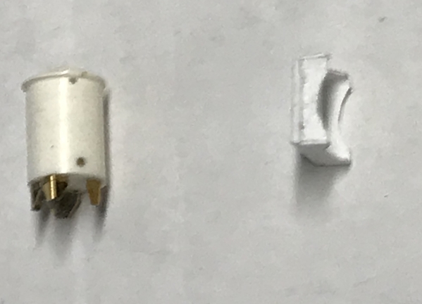
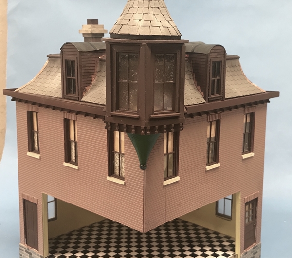
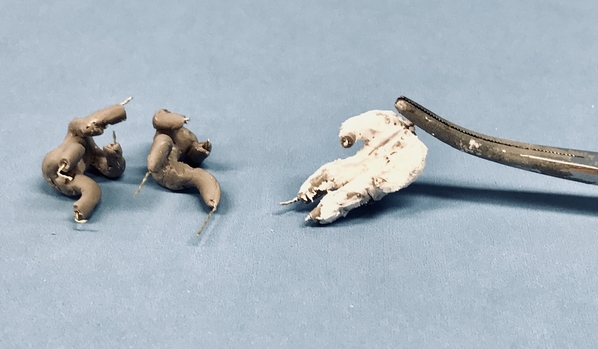
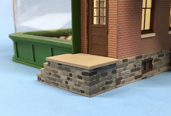
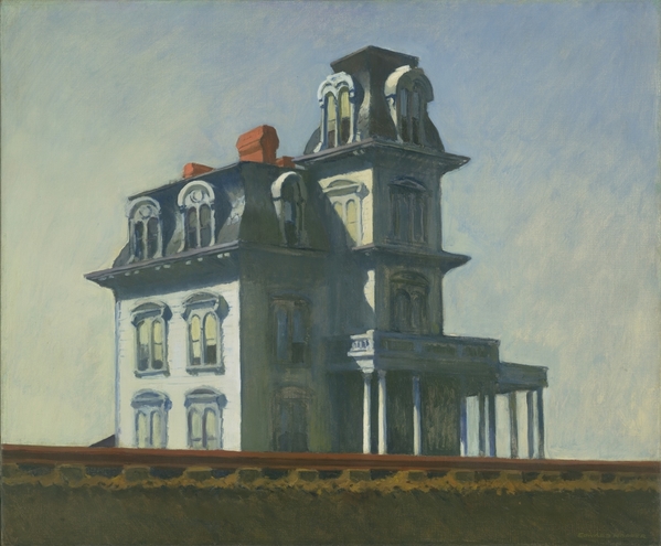
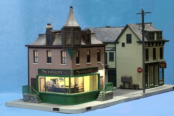
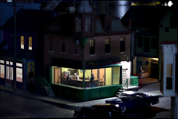
Making these stools was ridiculous. I had enough cut to produce 12 stools. I ended up with 7, and even with that, it's touch and go. They're sooooooo fragile. I had 8 done and set in the back of my work zone. A glue bottle bumped into them and two disassembled. I was able to get one back together. Instead of trying to paint them with clear gloss, I ended up dipping them into the bottle of Tamiya Clear Gloss. This worked okay, but even getting my tweezers to let go broke some joints that needed repairing. Next time I do this (actually, there never will be a next time) I would have them cut out of 1/32 aircraft ply or laser board. Laser board is rugged, but it's not wood and would need to be painted. This picture is before dipping.

NH Stools

I also coated the counter assembly with two coats on the sides and three on top. I sanded between coats with 3600 grit wet abrasive cloth. It's very wet in this image.

NH Counter 3rd Coat

Next up was the Westport Model Works resin coffee urns. They had a square plastic pad that was supposed to the the base, but it wasn't good enough for me.  So I first made a styrene set of supports for the square. I didn't like how it came out, so the next version was some brass legs bent and cut from PE sprue material.

NH Urn Base Choice

I covered the cylindrical exterior with Bare Metal Foil, and painted the top and legs with the Molotow Chrome Pen. Didn't know what I did without this exceptional source of very bright, metallic finish.


NH Urns WIP 1

Westport included a soldered assembly to represent the spigot, handle, valve and level tube. I installed this and then painted it also with the Chrome Pen with a touch up of semi-gloss black on the valve handle. Just tried it in the building here. I'm worried that gluing the stools in before all the front window work will put them in jeopardy. They're that delicate. Westport's urns appear to be of two different sizes.

NH Urns Done

I think I'll put all this aside and start working on all the details that surround the curved from window. There's trim above and below that will need to be crafted. I also need to start building the turret room, the mansard roof and the gables. Lots more to do. Just for the heck of it, I may attempt to build some stools out of styrene. I have the proper sizes to do it. Styrene does give you the opportunity to weld the pieces together which may be more secure. These stools could also be 3D printed in a laser/resin process. 

When we went with grandson #1 a week ago to visit the University of Wisconsin, we got to tour their "Maker's Space". They had 9-filament additive machines and 5 FormLabs Laser/Resin machines. The laser machines, since they put no torque or load on the part being created, have very high resolution and can do intricate shapes (Bar Stools) without lots of supporting webs. I was drooling and wanted one in my shop. Unfortunately, they're over 3 grand and that would make some very expensive bar stools. It's the modeler's dilemma.


Attachments

Images (5)
  • NH Stools
  • NH Counter 3rd Coat
  • NH Urn Base Choice
  • NH Urns WIP 1
  • NH Urns Done

I'm not following daily, because I want to view "Nighthawks" as a whole, enjoying the finish and working back into the build in a reverse order. I have always loved the image.

However, I caught the Afib out of the corner of my eye..... So good to hear it is mild. Mine is ok, but Afib runs strong in this family as well, even some teens. Hasn't killed anyone, just there.... or not there when it skips

I started having occasional irregular heartbeats shortly after I was married in 1968. I don't think there's a direct connection. I was also a first year shop teacher in a rough school (actually teaching middle schools kids is rough under any circumstances), and I started having full-blown anxiety attacks when I got those irregular beats. It was the anxiety attacks that had me firmly believing I was going to die in my 20s. I didn't know what they were and they scare the crap out of you. It took years and some very serious introspection to gain control over them. Now I'm going to be 73 on Monday so I guess my fears weren't very well founded.

The aFib was kind of new since my irregular beats were mostly of the pre-ventrical contractions (PVCs) variety. What really solved my anxiety problem was very bizarre. I will tell the story. 

In 2005 a very close friend of ours had a myocardial infarction. She's 5 years younger then me. With my crazy heartbeats, I started having sympathy symptoms. Then, on a business trip to San Francisco, I almost thought I was going to croak after dragging my roll-around travel case up one of those ridiculous hills. I went for a stress test. 

I finished the test, and the thallium die showed that immediately after the test that my central coronary artery was not profusing properly. After resting, the flow was fine. So they scheduled a cardiac catheterization. I'm a techie so I was watching the monitors during the test and could see nothing wrong (a layman's view), but the first test they do is insert the probe into the ventricles to measure various parameters. When he touched the inside of my ventricle my heart did the same palpitation that it had been doing for 25 years. I asked what he just did, and the doc replied "You have sensitive ventricles". And the then touched it again and the same reaction happened. I had an epiphany right there on the table.

One of the typical times when I would get the PVCs when we'd be on the interstate and passing over the expansion strips just when you enter an overpass. That jiggle was just enough to shake my torso and cause a PVC. And of course we'd be driving at 75 mph, and then I'd be fighting an anxiety attack. Now… all of a sudden, I find that it's MECHANICAL!. It is not pathological. It explained a lot since the PVCs also happened when I was scrunched over my computer (terrible posture) and my rib cage was compressed. 

Oh… as an upshot, my catheterization showed no occlusion of any artery. While on the table the doc said he "wanted to trade arteries." So my cardiologist dismissed me since I wasn't a heart patient. And that was kind of the end of the anxiety attacks since there was there nothing really to be anxious about. The aFib happened much more recently, but since it's not fatal, and I know exactly what it is (and why, since I had an echo cardiogram which showed a slight Left Artrium dilation which can cause aFib) I don't have any anxiety attacks over it.

I'm writing all this because others may be having similar, weird things that are scary, but you don't feel comfortable telling anyone about them. In the 70s, after I had the anxiety attacks for about 10 years, I was having lunch with a vendor and somehow the conversation led around to them. He had them for many years and controlled them, by self-hypnosis. I was relieved to find I wasn't the only person in the world with this affliction and found that I could stop the attack if I caught it just as I felt it kicking in. If I didn't catch it right at the beginning it would go the full monty. Sometimes I did, and sometimes I didn't. 

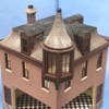
Back to train stuff. Started building the two-layer Mansard roof which gives this late 1800s building so much character. There is the lower roof which spans the width of the building plus a small 1/8" overhang on all sides, plus the attached base for the turret. 

Instead of pasting the plan onto the large piece of 1/16" aircraft ply, I laid it out the old fashioned way. I made datum lines and measure x and y coordinates to set up the intersection points for the hexagonal turret.

NH Lower Roof Layout

I drilled the 5/16" hole in the center of the turret space for the pin on the lower turret dome and then fit it to the building as a test… and it passed.

NH Lower Turret In Place

The Mansard curved walls are supported by six formers that held together in egg-crate fashion. I did all these layouts on SketchUp and then Illustrator/CorelDraw so I was pretty sure everything registered properly. I glued the plans to the ply and then cut them out individually on the scroll saw. A little clean up of the straight edges on the belt sander, and then clamped the sets (3 each) together to finish sand the curve with a Dremel sanding drum and opened up the notches so they would fit together. I suppose I could have screwed six pieces of ply together and cut them all at once, but that's an afterthought.

NH Mansard Frames Patterns

I glued them together with CA and Aleen's and held them flat to the surface with a piece of ply (the upper roof) and a heavy cast steel angle block so they would dry nested together properly. Not glued down yet in this image.

NH Mansard Frames

After gluing down the frames (again with Aleen's and CA weighted until it set), I dug up some old and very poor quality balsa sheeting left over from the monster B-17 project that was completed 8 years ago. I learned a trick building that plane; soaking the balsa with vinegar to make it pliable. Normally you wet the convex side of the curve where the grain swells and helps form the curve in the direction you want, but this balsa is so bad I soaked both sides. I used this balsa to build the bomber's fuselage and it was just awful. I scrapped all of it for the wing skinning and bought all new material. This is not that good stuff.  I had to find pieces that weren't already split. After soaking them I glued them down with both thin and medium CA.  I estimated the corner joint on the first piece by holding a straight edge held as close as I could with the diagonals I drew on the roof and used a #11 blade to cut it that shape. I then used that newly cut edge to trace the intersecting next piece and trimmed accordingly.

This was much easier to do on SketchUp. You skin both edges and click on "Intersect object with model" and it puts lines on the drawing where the parts contact one another. You just erase the extraneous edges and you have a perfect junction. It's a bit harder in real life.

NH Mansard Roof WIP 2

I ran out of time and have one more face to install. I will finish sand the corners and the base and then paper them over with first, black construction (tar) paper, and then with Rusty Stumps Victorian Fish Scale Shingles. Before I do that, I will paint the exposed portions. I also cut the upper roof flat, and then will cut the slightly pitched actual upper roof surfaces and their triangular supports. These too were laid out from SketchUp. I will put up a barrier board around the roof's perimeter (rain gutter). Downspouts will connect to scuppers. 

I have a lot of errands run tomorrow and Friday which may curtail a lot of shop time, but I'll try. 

Attachments

Images (5)
  • NH Lower Roof Layout
  • NH Lower Turret In Place
  • NH Mansard Frames Patterns
  • NH Mansard Frames
  • NH Mansard Roof WIP 2

Finally got a couple of hours work out of fastly-growing #2 grandson. He leaves on Saturday to visit other set of grandparents in California, and when they return school soon starts, so this session may have been it for a while. He turned 14 in June. That is not a real Herman Miller Eames Chair he's sitting on. It's a 40 year old knockoff we bought in the late 70s. The real one is upstairs without it's bottom cushion since a button popped off and it was sent back to H-M 5 weeks ago. They take a lonnnnnnng time to do warranty work.

NH Helper Making People

He made some sugar dispensers and napkin holders and then started working on the first person. Making O'scale people from scratch is not for the faint hearted and I really wonder how Artista does it. Sugar dispensers are clear scrap plastic model sprue paint the that Molotow Chrome Pen and some white put on with a toothpick.

NH Suger Containers and Napkin Holders

I probably will need to make the people because at some time in the not-to-distant future they would be on the critical path and will hold up buttoning up the building.

While grandson was doing his work, I was continuing to work on the Mansard roof. I glued on the upper roof base and trimmed the edges to conform to the curved lower roof. I then cut from patterns the upper pitched roof panels and the angle supports that lie underneath. I had to sand and trim the supports so they were all the same. This picture shows the in-process step of the gluing the roof pieces onto the forms.

NH Upper Roof Construct

After all four pieces were in place, I added some filler material under each of their exposed edges and used thin CA to tie it all together. Sorry about the soft focus.

NH Roof Before Filling

Last thing I did was add a bunch of joint compound to fill in all the remaining gaps and blemishes. This will be soldered next session… tomorrow? Not sure… exercise and then taking grandson to tennis practice. Otherwise, it will be Monday, which BTW is my 73rd B'day. I'm going to use some Balsarite balsa conditioning coating to seal it and make it more secure to accept the adhesive on the "tar paper" that goes one next.

NH Roof with Mud

While this was starting to dry, I began working on the turret structures themselves. I'm using styrene for all the construction other than the lower plate since it so easy to hold together with solvent cement. As I was cutting the other plates to support the window sets I realized that the two small edges of the bottom hex plate go back into the building at right angles to the building and NOT the correct angles to complete the total hexagon. But, the rest of the tower needs to be hexagonal. We'll see how this works out.

This building is why model railroading is such an amazing hobby. It uses techniques from all kinds of model making, even including miniatures and doll house building. It has some electronics in the LED lighting system. It uses scratch-building model airplane techniques in the use of former and balsa skinning. And lets not forget fine arts sculpting in making those four tiny people. I am not good at sculpting and am not hopeful that I'll learn how to do it soon enough.

Attachments

Images (5)
  • NH Helper Making People
  • NH Suger Containers and Napkin Holders
  • NH Upper Roof Construct
  • NH Roof Before Filling
  • NH Roof with Mud

Your grandson did a great job on those small items.  I agree, I am amazed at how folks can make such small items so realistic.  Our older daughter has the knack!  She got it from her late maternal grandfather.

On to the Mansard Roof!  That is quite an undertaking as well!  Well, it seems tough just like the turret!  You are doing a wonderful job, and of course the choice of material and methods have a lot to do with it!!  We once lived next door to a house with a Mansard roof, and I would often look at it in respect for the builders.

Thank you as always...

Very short session today. I sanded the joint compound on the Mansard and added just a tad more to further fill a depression. Joint compound shrinks a bit so two coats is often needed. I then got back to the turret structure.

The upper turret roof is framed in 1/8" square styrene that serves as a spacer and the upper structural framing supporting the windows.  I then sanded the injection molded Tichy windows on the True Sander so the edges were truly square. I set the Chopper fence to cut more 1/8" stock to make the side framing and glued these to the windows. I had sanded one end of the square stock and cemented it flush with one end of the window frame, and left the side pieces just a but long which I'm then sanding square and flush on the sander again.

NH Turret Build 1

And then, as you can see, I ran out of 1/8" stock and will run to the LHS today while grandson is at his tennis lesson. Won't have any time when I get back to work more so it will wait until Monday. There will be some corner gaps as I glue the four windows around the turret and these will be filled with some flat stock that will meet tightly in the corners. I will look pretty good. I will have to glaze all the windows before gluing them to the turret since access will be limited.

Went to the LHS and got what I needed, but as predicted, by the time I got home from the tennis lesson, the day was over.

I was seriously about to buy another plastic kit to build; a Takom kit of the M1-A1 Abrams MBT with a complete interior including the gas turbine power pack. I've been looking at it on line and saw it at the shop last week. So I was going to buy myself a birthday present and… it was sold. So if I want one, I'll have to order it and then it won't be an impulse buy, and I'll have to be thinking about it more. Then there's the problem of having about 8 other high-scale models on my wish list and if I'm ordering one, should it be that one? Oh! The decisions that I'm required to make. And then there's more train stuff, getting the Bronx Victorian laser cut, and getting to work on the engine house. Will this torment ever end???

Thanks Pat… yup! That's the general idea. Getting them in the young impressionable age...

Friday's image didn't post…hmmm.

Today I assembled the turret's window structure. I had to buy additional 1/8" square to do it and got to work today to finish this important step.

The side rails were joined to the sides of the trued-up window frames, both ends sanded so they were flush and square and then joined to the upper hexagonal frame which had it's own 1/8" square stock added. I used the centering lines on the hex pieces to guide the razor saw to create the joint angle. I then adjust the angles slightly on the True Sander.

NH Turret Build 1

While I had created a full-circle of supports on the hex piece, this was in error. Actually the hex is open at the back and connects into the attic with a hallway of sorts. So I removed the back two framing pieces and adjusted the hex piece as you'll see in this next image.

For window glazing I decided against using styrene but tried something else. Many, many years ago I was getting my shirts laundered at a place that included some nifty acetate collar protectors. I ended up saving them and throwing hime in a box thinking that, "someday I might need this acetate to make windows in some building or another." That day was today.

I had to cut the pieces to a measured width with the calipers, then cut one true end at right angles, then measure and scribe the other length and cut that. They make nice windows and I glued them in with the Formula 560 canopy cement. Dries clear. Doesn't fog or craze acetate.

NH Shirt Plastic Windows

I needed to then mask the window frames and acetate so I could spray the entire turret without fouling the windows AND I could glaze the windows AFTER putting the turret together since there's limited access.

NH Turret Window Masking

Instead of attempting to glue the styrene window frames to the wood turret room floor, I made a another hex piece that would hold the window frames and this would be glued to the wood substrate. Here's the windows glued to the bottom frames. The rearward view shows the modified hex plate.

NH Turret Windows

The gaps at the frame junctions needed to be filled. I'm doing this with some thinner strip stock joined at their edge. I just got the first corner done before we had to leave for my birthday dinner.

NH Turret Trim Start

I had to try it out on the building. I'll be building a clapboard wall that will be coped to snuggle against the Mansard portion of roof, continue over the top to the mid-point. I'll then build a mildly-curved roof similar to those that will run back from the gable windows. You can see the added piece I put on the hex plate to change its configuration.

NH Turret Fitting 1

Getting the turret built was a big step and a critical one to the appearance of this building. I had to change its dimensions since the Tichy windows were taller than the laser cut windows that were part of my original design. In fact a lot of thing changed when I went from the laser cut to the DIY build.  I'll be making a cardboard template of the side walls since they're going to require some fancy cutting to nest into that roofline.


Attachments

Images (6)
  • NH Turret Build 1
  • NH Shirt Plastic Windows
  • NH Turret Window Masking
  • NH Turret Windows
  • NH Turret Trim Start
  • NH Turret Fitting 1

Thanks guys! And Boy! What a load of effort. I did have a computer drawn template from the laser-cut version which I could have used to build the intersecting curve, but I change both the size of these side pieces AND the angle at which they join the roof so that drawing would not be accurate. Instead, I first cobbled together a cardboard pattern which I thought (notice that word…thought) was a curve match (top picture). I traced the pattern onto some clapboard siding and cut it out. It didn't fit! So I added pieces to the back to keep approximating the curve. (bottom picture). Point of information:  

NH Side Panel Fitting

This happened on both side pieces. I then traced that piece and made a second set out of clapboard. These were better, but there were still gaps that were too big for my standards. I then traced these pieces and then adjusted the curve to further close the gap. This third set worked pretty well, but the left side was still not as good as it could be so I made one last piece. That makes 7! It took just about the entire afternoon. Make sure you're cutting the clapboard with the boards facing in the right direction. I made this boo-boo when cutting the last version. DOH!

But the results I think are worth it. I had to put more backing pieces behind these panels so there were places upon which to glue them. I will also add some thin trim pieces over the junction between the windows and the panels.

NH Side Panels

I have absolutely no idea if this is even a remotely prototypical way to bring a turret into a building. It's different than my 1957 article and is different than my first set of designs, but it should work...

For the roofing over the turret hallway, I'm going to make it a slightly curved roof that will transition to the flat front roof. I made some formers to support this roof. The last one was still curing and will go behind the other two. It will be covered with "Tar Paper".

NH Turret Roof Formers

I took a picture on the sun porch with the top and bottom turrets in place.

NH Turret Status 2

Something was missing. Actually, several somethings. There needs to be something under the top turret which I cut as a circular piece of 1/16" ply that will extend out to the points on the hex roof. And then threes more work on the bottom. There is a small dentil molding that is under the main roof edge and also wraps around the underside of the turret. I had already CA'd the lower turret in place when I realized that more work was needed so I popped it off. 

The first step was to make a backing spacer to support the band board that the dentil pieces will be glued. The dentil pieces are going to be 1/16" deep (0.063") and the band board will also be 0.060" so I made a hex piece that was .123" back from the turret edge. The band board will only be under the turret. The dentil will be glued to a much thinner piece around the building perimeter since I only have a 1/16" roof overhand with which to work.

NH Under Turret Spacer

I have some half-round Evergreen strip stock to put a nice edge on the upper roof, and I have to build the s dormers and the chimney. For a little (6" square) building, the roof has plenty of challenges. It's a curse… I never pick stuff that's run of the mill. BTW: the roof has some 1/8" strip wood stock now placed so it can be easily removed and replaced. I don't like gluing down roofs unless I absolutely have to.

Attachments

Images (5)
  • NH Side Panel Fitting
  • NH Side Panels
  • NH Turret Roof Formers
  • NH Turret Status 2
  • NH Under Turret Spacer

Last session until Tuesday. Visiting our son and family over the weekend.

Continued work on turret refining the look with trim pieces and buttoning up the bottom making it ready for the dentil molding. Glued the lower plate to the upper turret, and started working in earnest on the gables.

I added the band boards to the perimeter of that hex piece I cut yesterday and then traced it's outline onto another piece of 0.040" sheet styrene, cut that our and glued it to the previous assembly. While it dried I laid out the 1/16" offset line on the turret bottom which would be where this assembly will reside. I then added some thin strip stock to trim off the area below the windows since there was exposed plywood there. I sanded the sides of the bottom assembly and then thick-CA'd it to the turret bottom.

NH Turret Final Trim

I finished up the formers for the hallway roof and then sheathed it with thin (0.010"). It's a slightly compound curve and therefore, the un-stretchable styrene is not particularly flat. For the roofs stemming from the gables to the center of the building I'm going to carve the shape out of balsa. I probably could have done the same for the hallway roof also, but didn't.

Here's a picture showing why the turret bottom is notched and how nice it snuggles next to the building.

NH Turret Underside Fit

I glued the base plate to the upper turret roof. It needed to be clamped to get the two pieces nice and tight, but the turret roof has that brass pin so I needed to compress the parts with clearance for the pin. I used an old socket wrench socket and clamped it in the wood working vise.

NH Gluing Turret Bottom

For the gables, I'm taking a different tack. Instead of trying to cope the side pieces to match the Mansard curve, I just made a couple of parallel cuts and removed the Mansard in that area. This means I can just build a straight cut side. I have drawings of the gable facings and again spray glued the drawing's back and stuck it to the backside of the clapboard sheet (making sure to check to see which direction the boards were going). I cut the window opening before separating the part from the big sheet to give more to hold on to. And instead of trying to bull my way through with the Xacto, I made three cuts to establish the line and then finished up with the micro-saw. This put a lot less stress on the part and gave a nice square edged hole. I then cut the rest of the perimeter the normal way. 

I awoke this morning thinking about how to make the gable rounded roofs. I didn't want to go the same route as I did for the hallway. I decided to recheck the 1957 article and, even though the whole building was illustration board and strathmore (old school for sure), he used carved balsa for these gable roofs. I have no probable carving balsa as can be seen in this picture of the huge amount of carving I had to do to make the four engine nacelles in the 1:16 B-17. The side and rear parts are carved from solid balsa.

Nacelle fairing bottom outboard 01

I don't have any balsa blocks so I glued up a stack of scrap that I had. I ended up with enough to do the three roofs… just barely enough so I can't screw any up. Luckily, the two gables' roofs that flank the turret aren't that long since they terminate at the hallway edge, not going to the very center of the roof.

NH Balsa Stock For Gable Roofs

I glued up one gable and tried it for fit. This method will work well, and solved a bit of a challenge and saved a few minutes of finicky work. Before gluing up the first one, I traced its side panels for the other two windows. I almost didn't do that, but caught myself. Again, had to pay close attention to the clapboard's direction. I also would like the boards to match from front to side. I'm not worried about the little imperfections at the gable cut edges since this will be hidden by shingles and flashing. Speaking of flashing, the roof will be "slate" so the flashing should be copper, and I have that terrific adhesive copper foil tape that I'm using for the surface mount LEDs that will work perfectly. I can even chemically treat it to get a natural patina.

NH Fitting the Gable 1

So until next Tuesday, Y'all have a nice weekend. In looking at the picture, I think I'm going to chop out half the mullions in the gable windows so they match the configuration of the rest of the building's windows.

Attachments

Images (6)
  • NH Turret Final Trim
  • NH Turret Underside Fit
  • NH Gluing Turret Bottom
  • Nacelle fairing bottom outboard 01
  • NH Balsa Stock For Gable Roofs
  • NH Fitting the Gable 1

Thanks guys! Just lost the entire post because I left the page without posting it. DOH!

The visit was good. My son is having a new house custom built and it's a big house that is now fully in sheetrock. There are many, many decisions that they're making on everything. I warned him that doing a custom home is an experience that can get very onerous. It's going to be a great house, but it's a lot of work.

Instead of stopping overnight, we drove straight through on Sunday. Instead of the usual 9.5 hours, the trip took almost 11 due almost entirely to nine, single-lane, 55 mph, long construction zones, a couple of which had significant backups. But I did do work yesterday and today, but didn't post last night. This post then covers two sessions.

I finished cutting and gluing up the plastic parts of the three gables and trimmed the middle horizontal mullions from the gable windows to match the style of the rest of the Night Hawk's windows. I then cut the balsa that would be the rounded gable roofs. The first one I did incorrectly. I made it so the wood fit between the plastic sides.

NH Gable Roof Problem

This position made it impossible to properly shape the roof. I did the other two differently, putting the wood on top of the side rails using thick CA. I then went back and re-skinned the incorrect one with thin, vinegar-soaked balsa and re-shaped it. There was a lot of area needed filling which I did using Milliput 2-part epoxy putty. This needed to cure completely so I let it harden overnight before attempting to grind it to shape. This picture shows the putting before finishing. Another mistake I made was using thin styrene sheeting to make the hallway roof. That too should have been shaped balsa. As a result the roof has a lot of crazy surface shapes. I am hoping that when covered with roofing paper and shingles the topography will be less obvious. That said, old roofs on real buildings can be pretty irregular too.

NH Gables

Today, I used the Flexi-shaft Dremel with a sanding drum and re-contoured the most obvious lumps and bumps. There were some smaller divots that needed filling so I used Tamiya filler this time. While this was curing I started building the chimney.

The chimney is made of four pieces of Plastruct brick sheeting and some square stock. I beveled the edges so the bricks would match at the corners and further helped by aligning the short and long bricks so the corners look right. The top works are pieces of various sizes of Evergreen styrene. The top has a hole in it which will be enlarged to fit the flue tiles. It is not finished and needs some filing, filling, mortar, painting the "concrete" and weathering.

NH Chimney Construction

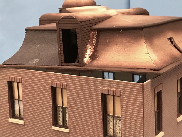
Like with the gables, instead of shaping the chimney to nestle up to the irregular Mansard curve, I cut a "square" hole in the balsa roof. It's not a square since it's entering the curve at a very oblique angle. When the balsa is removed, there is a structural member, the former, behind that would block the chimney from sitting down. Instead of attempting to cut this web away, I simply notched the chimney. Here it is being test fit on the roof. You can also see in this image that the roof filling is much more regular looking although still not very good. I also glued on some half-round Evergreen trim on the roof upper edge to clean up that edge. It works. All the gables, and trim will be airbrushed with flat brown before roofing material goes on. I'm using the adhesive backed copper foil for all the roof flashing. That too is going to look very cool.

NH Chimney Fitting 

Oh… and one more thing. I've gotten firm communications from Railroad Model Craftsman magazine that the 3-part Bernheim Distillery construction article begins with the October issue. This thing's really happening!

Attachments

Images (4)
  • NH Gable Roof Problem
  • NH Gables
  • NH Chimney Construction
  • NH Chimney Fitting

Thank you! I do think the roof is what sets this building off, and will even overshadow the interior work that is yet to be completed.

Finally got back on the recumbent bike today so work in the shop started at 2:00. I was able to put everything on the roof needed to be placed before painting could begin. I forgot to add the boards that would delineate the rain gutters, so I'll add them tomorrow and just airbrush that part. I also completely finished the chimney except for weathering. And I got started on the dentil moldings with their installation on the turret. I glued the bottom and top turrets spires (or whatever they're called) and then airbrushed the exposed areas that should be painted Tamiya Flat Brown.

I glued up a square tube that would be the chimney flue pipe measuring about .337" on a side, filed the corners round, and then cut it to appropriate length. I then opened up the hole in the chimney with a carbide router and files and glued the flue in place. I used a tiny bit of filler to clean up the joinery and then started painting. I first painted the mortar like I did with the main building. I then brush painted the masonry work at the top Model Flex Sand, and then painted the flue Vallejo Flesh Shadow which is a terrific red-brown shade that's good for lots of things including rust, bricks and terra cotta. Lastly, I painted the flue interior and top edge Tamiya Flat Black.

NH Chimney Make

What's left is using weathering powders to put some strategic soot around the top and flue. I'll add some weathering to the brick work also.

The original Model Railroader plans (1957) showed a simple dentil molding with a hemispherical notch. I used some 0.040" X .188" Evergreen stock which I laid out with the calipers and dividers. I don't even know what drill size I used to put the curved shape, simply choosing one that looked right. The dentil width is .100" and the centerline is .094". I laid out these lines and used a divider to step off the hole centers at .200". I pilot drilled with a 0.032" carbide drill and then followed up with the selected drill size. I drill about half way through from the front and then turn the piece over and drill the rest from the back which leaves a hole with no burr to clean up. I then set up the Duplicutter to slice off the .100" pieces attempting to slice the hole perfectly in half. This worked…sort of. Even though the razor blade in the cutter is thin, the body of the blade is still thicker than the razor edge. This puts sideward pressure on the workpiece as it cuts and this force is then putting pressure on the steel rule that clamped to serve as the cutting fence. It moves! Not much, but enough that the dimension creeps and the parts stop being cut in the center of the circle. I found that I was adjusting quite often and the sizes are not as consistent as I would have hoped.

NH Making Dentils

Rather than decide on a specific spacing under the turret, I glued molding at the ends of each section, then one in the center and then divided up the remaining space with what appeared to be the correct amount. It looks okay.

NH Dentil Molding Start

After I glued the remaining dentils around the turret I airbrushed the brown that would set out all the non-shingled area.

NH Roof Painting Start 1

We went out for dinner tonight and I went downstairs to find the copper foil which I thought that I put away and couldn't find it. So I searched the whole place only to find it sitting on the main workbench right where I left it. I decided to try out putting in some flashing. It's okay, and not fully trimmed in this picture, but I just wanted to see how it worked. I can't put it on in one strip since it's a concave curve and the tape would buckle, so I'm cutting it in smaller squares. I then went back and trimmed the stair step pattern that flashing often takes. I didn't finish doing this on the last piece I applied. I was concerned since the tape was not sticking well to the painted surfaces. Once the roof shingles are in place it won't be going anywhere. Also, the trimming action removes some of the brown paint that will require touchup. Pre-trimming the copper foil doesn't seem like it's going to work very well.

NH Copper Flashing Attempt

Attachments

Images (5)
  • NH Chimney Make
  • NH Making Dentils
  • NH Dentil Molding Start
  • NH Roof Painting Start 1
  • NH Copper Flashing Attempt

As usual, practice makes perfect. Unfortunately, the practice is occurring on an existing project, not a practice piece, so there is a great range of performance from the first copper flashing I installed to the last. It took several iterations before I really figured how to handle the foil and how to arrange it at the wall/roof junction.

Here's a series of images that shows the evolution of my flashing ability. I should have made a practice piece to perfect the method before doing it on the model.

NH Copper Flashing WIP

Here's the last joints that I did. I made the squares bigger, found a way to move them from the backing sheet to the model without having them stick to themselves, and using a solid long piece in the more vertical section of the Mansard. I spent more time burnishing the copper to the siding and didn't care as much if it was perfectly adhered to the roof itself since it was to be covered with first "Roofing felt" and then shingles. 

NY Copper Flashing WIP 2\

With the flashing in place in all adjoining surfaces, I started adding the "Roofing Felt" black construction paper. This was measured and cut and then fully coated in the backside with MicroMark Pressure Sensitive Adhesive (PSA) to adhere it to the roof.  I finished all but one gable roof and the next session will start shingling. I went to the LHS and got some more Evergreen strip stock for the rain gutter edging and a thin backing piece behind the dentils that will ring the underside of the roof edge.

NH Roofing Paper On

The gable and hallway roofs will get some more treatment to make them look more like composite roofing with "tar' seams at strategic points. The remainder of the roofing will get Rusty Stumps (now produced by Rail-Scale-Models.com) fish scale shingles (Mansard) and straight shingles (Flat Roof). Walt, at Rusty Stump, has given up all their laser cut products to concentrate on 3D printed ones. Rail Scale Models has purchased the drawings for the laser cut products and will continue to make them available. Their O'scale shingles are very good.

Shingling the top turret roof is going to be 'fun'. These kinds of tapered roofs when done in slate has shingles of diminishing size as you move up the taper. Slate doesn't bend so to get it around the decreasing diameter requires smaller and smaller shingles. I thought about buying HO and N scale shingles to do it, but that's a very expensive solution when I would barely need 1/10th of a sheet to do the job. So I'm going cut the O'scale shingles in such a way as to make smaller and smaller ones that will wrap around the roof. The lower turret dome gets no shingles and will be painted.

I was right. The paper covering has hidden all the awful surfaces imperfections on the roof. And when I add the "tar" it will be more realistic. There are to tiny triangular roof areas that flank the hallway that I'm going to paint semi-gloss black and not attempt shingle. Roof should be done on Monday or Tuesday.

Attachments

Images (3)
  • NH Copper Flashing WIP
  • NY Copper Flashing WIP 2
  • NH Roofing Paper On

Happy Monday! Thanks Mark, and I did get the shingling started.

On Friday I had the pleasure of having my young 8 year old protege, his dad and three-year-old brother over for some train running. His dad, who I've been sort of mentoring in his new roofing business, informed me that the flat portion of the Night Hawks roof would not have shingles, the pitch is too shallow. It would either be rolled sheeting or standing seam metal. Since the standing seam would add more thickness than I wanted, I went with rolled roofing.

I've been using left over sheet roofing from Bar Mills for years now since I substituted "metal" roofing on the Idaho hotel and Rusty Stumps shingles on the Gravely Building. This is a scale 4-foot wide adhesive backed fine grained paper. I airbrushed this with Tamiya Nato Black (a very dark gray) to give the roof a pre-weathered color.

NH Bar Mills rolled roofing

I tried as best as I could to have the overlapping seams running from the high side to the low. After all the shingles are done, I'm going to go back and hand-paint semi-gloss black on all the seams to simulate roof tar. 

NH Flat Roof Covering

After getting all the sheeting in place I went back and checked any loose areas that weren't holding as they should, I added a bit of help in the form of thick CA. When done, I added some thin pieces down the 45 degree angled peaks at the four corners to finish it off.

NH Flat Roof Covered

It was time to add the fish scale shingles. I started by adding the starter row that's a separate line item from Rusty Stumps and now Rail Scale Models. You put shingles on from bottom to top, and I began with the longest continuous surface. I actually made it more difficult by starting from the chimney cut and working towards the corner. This made it challenging to get the two sides in sync so the continuous strip that would be above the opening would align with both sides. Instead I should have just paved over the opening and cut the chimney opening AFTER the row was burnished down. To get the right side bottom started so it would at least be a little in sync, I held a full strip aligned with the left side (which I started first) and trimmed the chimney cut edge so the shingles would be continuous. But even with this extra care, you can see that the first continuous strip above the opening is not quite aligned on both sides. Only I will notice this!!

NH Shingling Start

Here's the job with the chimney dropped in. There will be chimney flashing on three sides so it will look spiffy. I also have to use a nice sharp blade and trim down the Mansard corner. Once shingles are complete I will take more copper foil down the seam. I will then carefully attempt to chemically age the copper, but may not if I see it's not working right. I will do a test off the model. I don't know what it will do to the paper shingles.

NH Shingling Start 2

Attachments

Images (5)
  • NH Bar Mills rolled roofing
  • NH Flat Roof Covering
  • NH Flat Roof Covered
  • NH Shingling Start
  • NH Shingling Start 2

The shingling is complete and so is the copper corner flashing. 

Due to slight variations in the starting point at the Mansard bottom, the top row of shingles in most cases needed to have a very small amount of material cut off the top edge so it would snuggle under the bead molding at the upper roof edge. The copper strips at the corner actually stretched a bit and conformed to the multi-directional curve the roof corner represents. I got one side of the copper to lay down and then burnished the opposing side starting at the bottom until it laid down on both sides equally. I also trimmed some of the roof edges on the gables. They were hanging down too far, plus they were starting to pull up and needed some CA encouragement to stay put.

NH Corner Flashing

Here's my usual status shot showing the roof as it is now. I added the counter-flashing to the sides of the chimney, but there's a gap that needs closing too. I need to go around with the Nato Black and carefully touch up the cut edges of the rolled roofing to hide the white paper underneath. I'm then going to do the tar strips.

NH Shingling Complete

Once this is all done tomorrow, I will need to shingle the upper turret roof. These kinds of roofs when shingled in slate have steadily decreasing sizes of shingles applied as you move up the taper. I will simulate this by trimming the Rusty Stumps square shingles to narrower strips with cuts to reduce the shingle width. I hope that works. I don't want to buy entire sheets of HO and N shingles for a couple of inches. I have to add a plumbing stack or two, and then finish the chimney and install it. Next, I'll add glazing to the 3 gable windows and install them. Finally, I'll go back and touch up the trim and add the board around the perimeter which will serve as the rain gutter. The overhang of the roof (1/16") is not wide enough to install a downspout. So I'll maybe add a couple of scuppers (boxes that collect and distribute the rain water into the downspout.

Attachments

Images (2)
  • NH Corner Flashing
  • NH Shingling Complete

Thank you, fellas!

Today I finished the roof! I'm glad since we're leaving Friday morning for an 8 day trip to Montreal and Quebec. I wanted at least the roof to be complete so when I return I can get to work on another part...

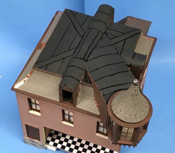
I accomplished several things today including: painting the tar strips, painting the lower turret drop, painting then shingling the top turret spire, painting the polished steel balls, touch up painted the brown, glazed and installed the gable windows, weathered the roof and chimney, installed the chimney and the remaining flashing, and did an experiment using the patina chemicals.

I used semi-gloss black for the tar strips instead of pure gloss. I just hand-painted the lines with a medium fine brush. Any irregularities simply make it look more like it was tar slopped on by a big brush handled by a roofer. This image also shows the shingled turret which I'll discuss in detail further in this post.

NH Roof Tar

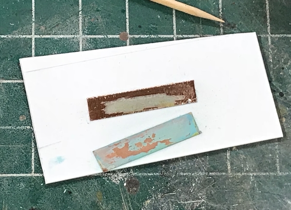
I decided to do a patina test to see if I wanted to chemically alter the bright copper. I put down two strips on a piece of scrap styrene. On the top one, I directly used the patina chemical. You're supposed to use a stiff brush and abrade the surface while applying the liquid. My brush may not have been stiff enough and the chemical only had the effect in a limited spot. I then read in the instructions and it noted that it would be more effective if the blackening chemical was used first. So the bottom piece shows this effect. The blackening chemical etched the copper much more deeply and the patina chemical formed the color on the entire piece. The patina is really not firmly attached to the copper and it does rub off, which is what happened where you see the bare spots.

NH Patina Test

With this test complete, I need to do one more. I proved that I can make the color change without having to dip the parts directly into the liquid, but I don't know what it's effect is going to be on the material surrounding the copper. I'll run that test tomorrow, and then I'll make my decision. If the roof was just installed, the bright copper would be appropriate, but I've weathered it a bit and the bright copper looks out of place.

I painted the lower turret drop Burlington Northern Green by Model Flex. The paint was pretty thick and I had to thin it with Testor's Universal Acrylic Thinner. It took four, hand-brushed coats all force dried with the hot air gun to get good coverage. 

It was time to shingle the top turret spire. The first three courses I used the standard Rusty Stumps O'scale square-edged shingles, but sliced the shingle further up into the non-cut portion so the shingles will separate more and wrap around the strange shape without buckling too badly. For the next 3 courses I cut the shingles in half, but kept their original length. For the next 4 course I reduced the length by a decreasing amount. Finally, for the last 5 courses, I cut the shingles in 3rds, and made them individual pieces since the attached strip was creating more trouble than it was worth.

NH Making Turret Shingles

The top three courses were treated to some thin CA at their top edges since the pressure sensitive adhesive backing was getting pretty skimpy and was no longer to be trusted. It's not as neat a job as I envisioned, but Frankly, the only way I could have done it better is with all the shingles being put on individually.

NH Turret Shingles WIP

To finish off the top row of shingles I wrapped a piece of thin Chartpak matte black tape to make sure that top row stays put. I couldn't use the thin CA there since it soaks into the paper shingles and discolors it.

To finish off the polished steel balls on both turret roofs, I dipped the ball into Tamiya Clear Blue (2 coats) so it looks like a glass mirror ball. When I started shingling I wasn't overjoyed how it was looking and seriously considered tearing it all off and painting the this roof also, but I persevered and from a distance it does have the look that I wanted. There is another mistake that I made that I can't correct. If forgot to paint (or remove) the bare wood roofing structure inside the turret windows. That train has definitely left the station since I can NO LONGER GET INTO THAT ROOM. I did remember to paint the inners behind the gable windows flat black, but neglected the turret. Partly because I had the windows all masked for most of the time so it was out of sight (and out of mind).

NH Turret Complete

I glazed the gable windows using the Formula 560 canopy cement, and glued them in place using Testor's tube cement. "Yes Virginia, I actually still use tube cement." I use it where longer drying times are helpful and/or there's some potential gaps that need bridging.

I weathered the chimney with dark gray washes and then black weathering powder. I also put some white highlight powder on the roof and some black smearing down the Mansard roofs. I could still add some more color variety to this roof is the likes of some green milder in strategic places. I then thick CA'd the chimney in place and added the remaining flashing to nicely seal up the area.

NH Roof Complete

I still need to add a stack vent which should go on the same side as the chimney.

Attachments

Images (6)
  • NH Roof Tar
  • NH Patina Test
  • NH Turret Shingles WIP
  • NH Turret Complete
  • NH Roof Complete
  • NH Making Turret Shingles

Last post before Montreal trip...

Ran the 2nd patina test. I'm not particularly happy with the change it made to the adjacent roofing shingles. And it is impossible to add the fluids and rub the darkening agent into the copper without having some of it wick onto the paper shingles. It really gives the copper a nice and very real—since it is—coloration. But I probably shouldn't go this route. #2 grandson suggested trying to do it with painting effects. I'll do an experiment on that approach too since I really don't want to screw that roof up. It was a 15 day project to build it.

NH 2nd Copper Test

I started building the extended roof gutter system that I brought up in the last post. I'm fabricating it out of a piece of .040" X .250" styrene strip with a piece of .060" X .125" strip glued to one edge and then a piece of .015" X .188" thin styrene strip attached to the combined edge. This profile forms the gutter proper. I chose the .125" piece to create a pocket where the actual roof will sit creating an extension of the plywood roof onto the styrene extension. And it's .060" thick stock so it matches the roof ply's thickness.

This assembly is edge glued to the extreme upper edge of the wall, and then another piece of the .015" X .188" is glued onto the wall under it to form the backing for the dentil molding. The dentil molding will also strengthen the bond to the wall also. In this image you can see the edge on profile. I reinforced the joint with medium CA.

NH Roof Extension

The ends are mitered at 45° before gluing them to the wall after carefully picking out the exact corner so the mating pieces will snuggle up properly. I cut the miter in a miter box and razor saw and then touched up on the NWSL precision sander.

NH Rain Gutter Trial

I was able to get two done before the session had to end due to picking up grandson at school. I had made this second piece the same length as the first, only to find out after gluing it to the wall that the right end had to be relieved quite a bit since it must nestle up against the turret structure. Whoops! So I noted where the interference was as best as I could estimate, cut off the extra with a razor saw, fit it again and cut off some more.

NH Rain Gutter WIP

It is still not fit perfectly, but that will have to wait until we come back from our trip. I did prove the concept of building the roof extension as a separate assembly, correcting the roof sizing error. We all make mistakes… it's how you recover. There will now be sufficient overhang to put in some proper downspouts.

So, I'll be reading the forum on my phone, but probably won't be responding so, y'all have a nice upcoming weekend and following week.

Attachments

Images (4)
  • NH 2nd Copper Test
  • NH Roof Extension
  • NH Rain Gutter Trial
  • NH Rain Gutter WIP
Last edited by Trainman2001

Thanks Pat! The trip was terrific, but now I need a vacation to recuperate. We flew to Philly, rented a Caddie XTS luxury sedan (split between another couple) and drove first to Hyde Park, NY where we toured the FDR homestead and library, then overnighted in Albany, NY. Then we drove to Quebec City, QC and spent one night and a day. We then drove to Montreal and stayed five more nights. We really did Montreal hitting the Botanical Gardens, the Museums of Modern and Fine Arts, and Old Montreal and the waterfront. My wife and I were at Montreal and Quebec in 1970 (we were 25) and didn't remember any of what we saw. That's because it wasn't there. Instead of a charming, restored French 18th Century village (Quebec), it was basically a run-down slum. Both cities were impressive and vibrant. We ended up eating in 4 star restaurants almost every night and all I wanted when we got home was a hot dog. The food was incredible! Actually, we had hot dogs in the food court of Chicago Midway Airport while waiting for our Southwest flight back to Louisville. We drove back to Philly yesterday. I gained 5 pounds! We walked our tails off, averaging over 4 miles a day. So it was good to be back in the shop building stuff. My body can't take more than a week of all that activity and food.

Today I got all the roof edging and dentil details completed ready for paint.

I made the dentil pieces as I did with those under the turret (speaking of turrets, saw a lot of neat buildings with them in Montreal). I needed a bunch of them and it took over an hour to drill and cut all of them.

NH Roof Edge Dentils

The only thing I had to pay attention to was the squareness of the back gluing edge. The Chopper, due to the shape of the razor blade, doesn't cut pieces with any thickness very square. There's usually a taper from the top of the cut to the bottom. If it was particularly noticeable, I trued it up with some hand sanding with the tiny part held in a needle nose.

I was initially going to space them about 3/16" apart, but got concerned that I didn't have enough pieces cut so I extended the spacing 1.5X longer and set out the marks with a tool maker's divider. Here's the first row glued on. As it was I had a ton left over, but I'm satisfied with the spacing.

NH Roof Edge Dentils Start

Since I wanted to have the dentils to start at the corners, I placed the first one there and worked towards the other end. In the case of the one wall that had no interruptions, I spaced them from both corners and let the slight irregularity fall in the middle.

Here's the building will all the dentils in place.

NH Roof Dentils Done

The last thing I did was mask the building so I can air brush the brown on all this trim. There was no way I was going to brush paint them. Instead of masking the inside, I cut a piece of cardboard to fit. I removed the outside stair while working on this since it was in the way. It just screws in so it was no problem to take it off.

NH Roof Edge Masking

Tomorrow I will paint this, and then there will be more more excuses to get to building the complex front window structure and then making those Edward Hopper figures.

Got the article proof and found out that it came off the press today. I got an eMail Friday that they needed the captions of the pictures going into this first part. Since I was about 1,000 miles from my computer, I ended up producing them on my iPhone in the back seat of the car as we rolled down the New York Thruway. I talked to them today and all of them worked and were in the article. Part 1 is 10 pages long.

Attachments

Images (4)
  • NH Roof Edge Dentils
  • NH Roof Edge Dentils Start
  • NH Roof Dentils Done
  • NH Roof Edge Masking
Trainman2001 posted:

Thanks Pat! The trip was terrific, but now I need a vacation to recuperate. We flew to Philly, rented a Caddie XTS luxury sedan (split between another couple) and drove first to Hyde Park, NY where we toured the FDR homestead and library, then overnighted in Albany, NY. Then we drove to Quebec City, QC and spent one night and a day. We then drove to Montreal and stayed five more nights. We really did Montreal hitting the Botanical Gardens, the Museums of Modern and Fine Arts, and Old Montreal and the waterfront. My wife and I were at Montreal and Quebec in 1970 (we were 25) and didn't remember any of what we saw. That's because it wasn't there. Instead of a charming, restored French 18th Century village (Quebec), it was basically a run-down slum. Both cities were impressive and vibrant. We ended up eating in 4 star restaurants almost every night and all I wanted when we got home was a hot dog. The food was incredible! Actually, we had hot dogs in the food court of Chicago Midway Airport while waiting for our Southwest flight back to Louisville. We drove back to Philly yesterday. I gained 5 pounds! We walked our tails off, averaging over 4 miles a day. So it was good to be back in the shop building stuff. My body can't take more than a week of all that activity and food.

Today I got all the roof edging and dentil details completed ready for paint.

I made the dentil pieces as I did with those under the turret (speaking of turrets, saw a lot of neat buildings with them in Montreal). I needed a bunch of them and it took over an hour to drill and cut all of them.

NH Roof Edge Dentils

The only thing I had to pay attention to was the squareness of the back gluing edge. The Chopper, due to the shape of the razor blade, doesn't cut pieces with any thickness very square. There's usually a taper from the top of the cut to the bottom. If it was particularly noticeable, I trued it up with some hand sanding with the tiny part held in a needle nose.

I was initially going to space them about 3/16" apart, but got concerned that I didn't have enough pieces cut so I extended the spacing 1.5X longer and set out the marks with a tool maker's divider. Here's the first row glued on. As it was I had a ton left over, but I'm satisfied with the spacing.

NH Roof Edge Dentils Start

Since I wanted to have the dentils to start at the corners, I placed the first one there and worked towards the other end. In the case of the one wall that had no interruptions, I spaced them from both corners and let the slight irregularity fall in the middle.

Here's the building will all the dentils in place.

NH Roof Dentils Done

The last thing I did was mask the building so I can air brush the brown on all this trim. There was no way I was going to brush paint them. Instead of masking the inside, I cut a piece of cardboard to fit. I removed the outside stair while working on this since it was in the way. It just screws in so it was no problem to take it off.

NH Roof Edge Masking

Tomorrow I will paint this, and then there will be more more excuses to get to building the complex front window structure and then making those Edward Hopper figures.

Got the article proof and found out that it came off the press today. I got an eMail Friday that they needed the captions of the pictures going into this first part. Since I was about 1,000 miles from my computer, I ended up producing them on my iPhone in the back seat of the car as we rolled down the New York Thruway. I talked to them today and all of them worked and were in the article. Part 1 is 10 pages long.

Had I known you were going to be in the neighborhood (only 34 miles due west of Saratoga Springs) when you were traveling up I87, I would have extended an invitation to visit and have some refreshments. The building continues to look awesome.P1000346

Attachments

Images (1)
  • P1000346

Oh well… I like how you did the Night Hawks, just put the picture inside… clever! I can do that in my case since I'm doing the whole deal in 3D and that means, little people. Ugh! Wish I could commission Artista to do it for me, but it would cost a fortune.

As planned finished painting the upper molding and got to work on the store window. Even though the extended roof edge was an afterthought (not on my drawing) it did work nicely. It was, however, in the original 1957 article, but I missed it when I redesigned the job for scratch-building.

NH Dentil PaintedNH Roof Dentils Painted 2

The Plexiglass window sprung back a tad after heat bending so it needed to be constrained a bit when assembled with the sills. I chose to build upper and lower sills with a containment groove that would capture the Plexiglass. A while back I had cut one piece, and I used this as a template for the other sill and the four framing pieces. I had to scrap a couple of them due to poor cutting quality on the scroll saw. I glued the pieces together with thick CA and sanded their edges after gluing to make them uniform.

NH Front Window Parts

A little piece of the end of one of the inner frames broke off in sawing, but it will not be seen since it's on the inside. I may glue a small piece of 1/16" ply to repair it before painting.

I glued the upper and lower frames to the Plexiglass using thin CA wicked into the junction. I just had to make sure that the top and bottom sill assemblies weren't cocked in any direction. The plexi was just a bit longer than the frames so I sanded it all square with the True Sander. I also finished sanded all the parts.

I tried the assembly in place to take a measurement for the lower sill construction. This will consist of a curved piece extending from the sill bottom to the pavement. It will be all framed with horizontal upper and lower pieces and a number of vertical cross-pieces. And it will all be painted a nice green.

NH Window Fit

I'm making this lower piece out of 0.040" styrene. It's a small enough piece to be bent without heating, although I did give it a little help with the heat gun. To help make the curve stable, I built a little former that will maintain the curve when glued in place. I made the former so it would not interfere with the Masonite floor plate that's well glued in.

NH Lower Window Former

I was concerned about getting this main window in place, but my concerns were unfounded. It went together better than I expected. Building the curved framing will be fun and I'm looking forward to that. I've been trying to figure out the best way to hold those super-fragile bar stools in place since the legs are sooooo tiny. I'm may CA a piece of brass wire down one that will go into a corresponding hole in the flooring to anchor it a little better. I also want to build some brass tubing foot rests on the bottom of the counter. I was looking at these on our trip and noticed that some are fastened to the bar and others are fastened to the floor.


Attachments

Images (5)
  • NH Dentil Painted
  • NH Roof Dentils Painted 2
  • NH Front Window Parts
  • NH Window Fit
  • NH Lower Window Former

Thank you all! I've always liked city buildings with turrets, although I never know what they're actually for. It would of been much easier if I didn't actually want that room usable since it was a real pain to build that angular hallway. 

More window work today, and it was a pretty long session so I got a lot done. First up was gluing the front panel to the bottom of the lower sill. I first glued on the former aligning it by eye as best I could in the apex of the curve. I used thick CA to hold it. I then glued some 1/8" sq. styrene along the glue line to support the extremis of the front panel. I used solvent cement and then followed this up with thin CA for a more secure junction. 

NH Front Panels Glued

I tried the window in with the panel.

NH Window Lower Panel

The window glazing itself is just about 1/8" proud of the building wall so I boxed it in with some 1/32" ply. I'm not sure if this is actually ever done this way, but I couldn't push the window in deeper without doing MAJOR surgery.

NH Window Boxing

It was time to finish the panelization of lower panel. I used a combination of 0.040" X 0.188", 0.040" X 0.125" and 0.040" quarter round trim. The upper rail was the .125 stock as were all the verticals. The bottom rail was the .188. I used the quarter round to trim between the top rail and the sill and on the bottom edge.

After putting in the extreme verticals, I estimated where the curve began and put a vertical on one side. I then measured this distance with the caliper and spaced off this distance on the other leg so the middle verticals were somewhat centered. I then divided the space between these verticals in thirds and marked a line that was then squared up with a machinist square. This was the center line for the verticals. Since when I glued them on I would obscure this line, I then put a little extension of it on the upper and lower rails so I could get it right.

NH Measuring the Panel Pieces

Here are the panels complete.

NH Panels Complete

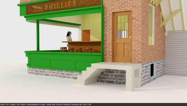
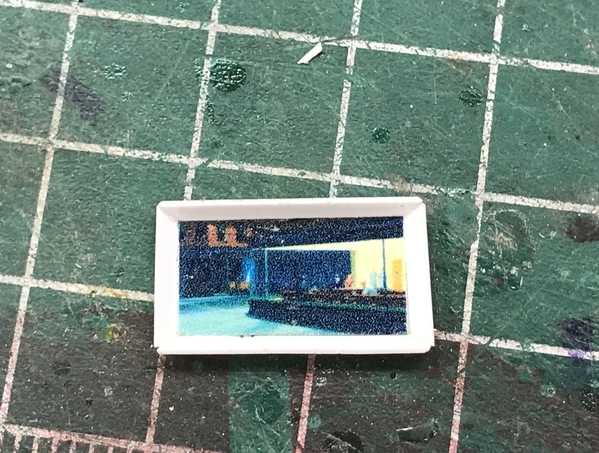
With the lower panels complete, I built the boards that would hold the Hopper "Phillies Cigar" graphic. I had isolated this image from his painting and then reworked the perspective so it was squared up. I cut the banner panels to fit from the building corner to the ends of the windows. This length measured 4.5". I then went onto the computer and sized this image so it was 4.5" wide. It looked a little bit skinny so I stretched the height a bit. I printed out a set of four on 5 X 7 glossy photo paper, but they were very dark, so I upped the exposure and reprinted them. This time the color felt right. I measured the exact height of the output image and used this to cut the banner panel height, plus 2 X 0.040" sq. stock that I glued on as a finished rim. I glued on the edging and tried it out on the building with a cut out Hopper graphic just put in place. I used final fixative for all my photo prints going into models to protect the inkjet ink.

NH Banner Test

All of this is going to be painted BN Green (Badger Model Flex) and since there's wood and styrene I took it all outside and shot it with Tamiya Rattle Can Gray Primer.

NH Priming Front Window

Before putting on the color coats, I needed this to dry completely, so I took the lull to start attempting to make the figures. UGH! This isn't going to be pretty.

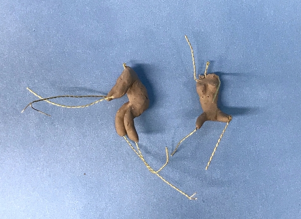
I made a wire armature with some 26AWG black iron wire roughly duplicating the size of an Artista sitting engineer figure. So far so good...

NH Figure Armature

Then I started to wrap it with Sculpey. I'm using the standard Sculpey which is pretty soft. Too Soft! I got this far. And I'm really not very good at this...

NH Figure ???

The process SHOULD go like this. First you put a thin layer on the armature and then bake it at 275° F for 15 minutes which sets the figure's posture. Then you add another thin layer of clothing and fire it again. You keep repeating this until you have a respectable figure. The instructions that I found were terrific, but they were for making a figure in 1:16 scale where you can apply much more clay and therefore, have more strength. At 1:48, the armature wire is almost too fat so the clay keeps exposing it. You push it one way and it exposes on the other side, then push it back and it exposes the wire on the first side. It was time to start cooking the rack of lamb we had for dinner so I stopped before I had anything worth baking. Tomorrow, I'm going to try using Super Sculpey which is a harder clay what will hold shape better while working. The beauty of this method is you can harden each layer so you don't undo what you've already done. I have some lighter gauge wire I could try as well. I keep y'all posted… of course. As has always been my modus operandi… I show you stuff that doesn't work as it should as well as all the successful stuff.


Attachments

Images (9)
  • NH Front Panels Glued
  • NH Window Lower Panel
  • NH Window Boxing
  • NH Measuring the Panel Pieces
  • NH Panels Complete
  • NH Banner Test
  • NH Priming Front Window
  • NH Figure Armature
  • NH Figure ???

After just doing a tiny sanding job on the primer, I air brushed the window assembly and the banner boards. It took three coats with force drying in between to get the color solid. I un-masked it and then cut the other banner out. I applied the PSA to the boards and after drying, attached the banners to it. The banners required a tiny bit of trimming in their width to settle in flat. I again stuck all this stuff up to the building and took another picture. I also primed and painted a 3/32" piece of brass tubing that will be the ceiling support in the front corner of the room. It too appears in Hopper's painting.

You can see something that I hadn't realized when I glued the window into the groove. Due to the 1/8" thickness of the Plexiglass the bare wood in the groove is now showing. If (and it's a big if) I thought about this effect, I could have painted the groove before installing the window. That's bad. What's good is just how transparent the Plexi is. It will really show the interior perfectly. I wonder if I could flow some thinned green paint into the groove….?

NH Painting Comp

While this was all drying I got back to my figures. I removed the standard Sculpey and re-wrapped the black iron armature with the Super Sculpey which is a stiffer blend. It still looks poorly and the arms are too short, but I fired it and added some upper torso bulk. Meanwhile, I decided to try a different wire for the armature. I have this 0.010" brass wire netting that comes from the top of a bottle of Spanish Rioja wine. It's great detailing wire!

Here's the raw wire.

NH Armature Wire Raw

The wire is twisted together to make a net pattern. I proceeded to cut off a section and twist the remaining wires together in groups of two using two hemostats to hold and twist the wire.

NH armature wire Twisted

I then turned this into a new armature.

NH New Armature

Using the new armature I made a new figure. I left the extremities quite long and will trim them when I fully understand how long they should be. Both of these figures are baked at this point. I will use the standard Sculpey for the detail layers since it's easier to work. You can already see that I'm rowing up the learning curve. Since I have four figures to make I'll have a lot of practice. I think there's an Artista figure for the counter man.

NH Figure Comparison

Attachments

Images (5)
  • NH Painting Comp
  • NH Armature Wire Raw
  • NH armature wire Twisted
  • NH New Armature
  • NH Figure Comparison

Short session today. We went to see the new movie about the capture of Adolf Eichmann. With the rise of far Right movements in Europe and here, people should see this movie to understand what true evil looks like. The rhetoric is repeating itself and the outcomes could also. 

I started figure number 3. This is going to be Hopper's wife so I decided to actually model her body first and then add clothing later. I figured if I could get the bare (no pun intended) contours correct, then adding clothes would be less difficult. Meanwhile, I also added the arms and upper torso of the man's body. I'm concerned that it's already too thick and I haven't detailed any clothing yet. I think the female body is almost the right dimensions. It will probably take five or six of these trials before I get it right. With the figures baked and hardened I can go back with a sanding wheel to reduce any areas that are overly thick without distorting the rest of the clay. That's the beauty of baking the clay in steps so you can fix previous work and not worry about it.

NH Figures 2 & 3

While they were baking I started working on the two sets of exterior steps. They both have to be set off the building by the width of those end window boxes. 

The outer contours are 0.040" sheet styrene. I want it to eventually look like poured concrete so the steps and side pieces will be glued and finished so it appears solid. I think I'm going to open up the space underneath the steps. This will increase the number of cross pieces that will have to be cut and installed, but it will make it more interesting  and not so monolithic. I have some some laser-cut hairpin railings that I may use or I'll have to find some other PE or laser cut products out there.  

NH Exterior Steps Start

I ordered some 30 gauge magnet wire to build some small LED exterior lights. I want a light over the entry door (the one on the right side) and a couple shining up on the banners. I can use the tiny surface mount LEDs and wired with magnet wire, they should make up nicely and not clunky. I show this later when the wire is delivered.

It's been a productive week, so everyone have a great weekend and enjoyable and stress free Labor Day!

Attachments

Images (2)
  • NH Figures 2 & 3
  • NH Exterior Steps Start

Saturday session. US Open is on and my wife has sympathy on me. I can watch tennis, but if there's something else more interesting, I'd rather do that.

I spent another hour fussing with those %_@*U% figures. The Sculpey does not like sticking to itself as much as I'd like it to. The wires keep protruding and I mess up as much as I sculpt in handling it. But I will persist. I would really like to see the man who run Artista do this so I could understand more of how to work in the small scales.

NH Figure Progress

The magnet wire arrived today by Amazon from two different sources. I'm going to experiment in making some very small LED fixtures with it. Red is positive and green will be negative.

Magnet Wire for LEDs

Lastly, I'm still noodling the design for the steps. Instead of making them a solid block of concrete, I might go with this. There, of course, will be a railing. Another possibility would be to make the solid step, but use the stone sheet that I used for the foundation wall. That would had some interest and be easier to build. The new design would involve a lot of cutting and fitting.

NH Step Option

Attachments

Images (3)
  • NH Figure Progress
  • Magnet Wire for LEDs
  • NH Step Option

Myles,

I asked my daughter about it.  She says she loves the Nighthawks painting.  I remember talking with her about modelers making models based on Hopper's paintings. She knows you are trying to do it yourself, but is interested in the possibility.  She showed me a photograph of one she is making for a 1:12 dollhouse right now, and said she is going to make me a surprise.

Making them in 1:12 is easier than 1:48, but that being said, I decided to do some more research today and have learned a bunch of stuff that should improve my results. So I'm not done yet.

One thing I learned was add the clay with the arms and legs straight AND don't put any on the joint areas. After curing that, you can bend the joints to the positions you want and add the clay to the joints. That was a real problem I was having since folding the clay around the pre-shaped joints just wasn't working. Furthermore, I really have to manage the clay thickness. The women is wearing a dress with short, tight sleeves so I have to model the arms as slender and feminine from the get go. Modeling the Fedoras will also be a challenge in O'Scale. The man (Hopper) has a very pronounced and sharp nose, whereas the women's is much more subtle. That cigarette will be very, very small… and she's holding, what appears to be, a pack of matches after probably just giving him a light.

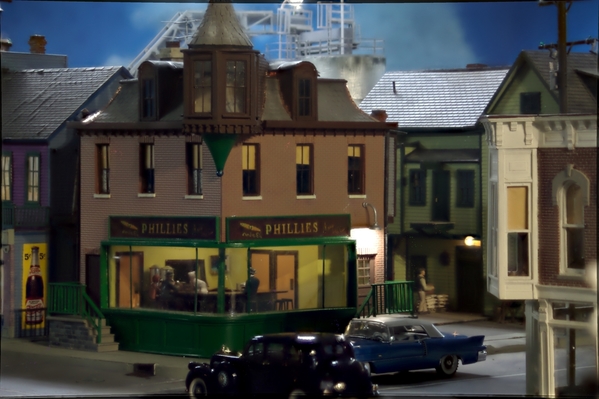
Nighthawks Master Art

So what I did yesterday just doesn't cut it. Another thing I learned was to actually build the torso and pelvic shapes out of something firm (like brass). I may actually solder the armatures together so they're tough and won't deform unless I want them to.

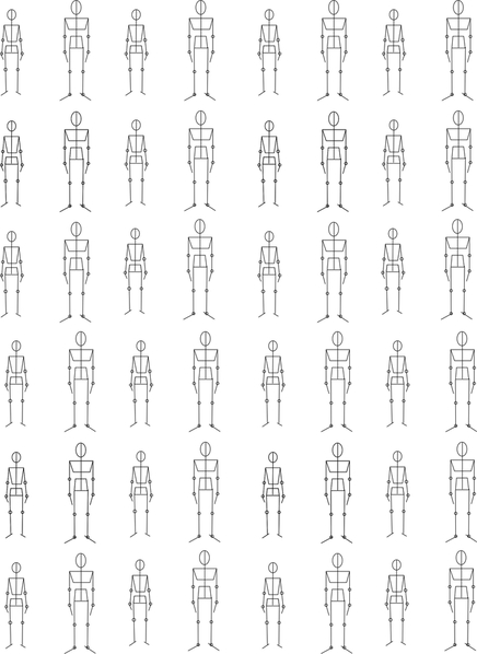
I then watched more videos and downloaded a bunch of figure drawing guides to get the proportions right so I stop winging it.

I actually had two terms of life drawing at Michigan State when I was still an industrial design major (3rd semester Freshman and 1st semester Sophomore years). I was the only man in a class of all women drawing nude women. Needless to say it was a bit "strange". All the horny guys on my floor in Bryan Hall would want to see my latest sketches. They all imagined it was some kind of "sexual" experience. It wasn't!! Quite the opposite. I was very self-conscious of the situation.

The 1st semester class was good with the prof wanting us to try and actually capture what the person looked like, but the 2nd semester's guy wanted more abstraction. He kept telling me to "loosen up and let go". I hated it, especially since I was heading for a career to draw photo-realistic cars (or at least that was the plan at the time.) In fact, my entire "fine arts" training those first two years were frustrating since I wanted realism, and art at the time was abstract with Jackson Pollack leading the way.

I will keep at it until it works. At this point in my modeling skills, I firmly believe I can do anything given enough time and practice.

Attachments

Images (1)
  • Nighthawks Master Art

Myles,

Thanks for sharing your ongoing adventures in figure modeling and the bits that you are picking up in your research.  

It is as interesting as your other posts.  I too hope to model some scale figures and am reading with great interest.  I will be trying some self-hardening clay that my  company gave us a huge block of for part of our December holiday gifts.  (They expect great artistic creativity out of software engineers and technical writers .)

With three and a half years' invested as a studio art major before switching to something better suited, I could truly relate to your stories about figure drawing classes, a preference for realism, and professors' "guidance" :-).

I also appreciate your "can do" attitude.  It gives encouragement to the rest of us. 

Tomlinson Run Railroad

P.S. Perhaps the woman in the painting is holding a sugar packet in anticipation of inventing Splenda?   Wow.  I just noticed how small the mugs are that Hopper painted.  They almost look like demitasse but not quite.

Last edited by TomlinsonRunRR

Sculpt all of the figures in 1:6th scale.

Then those 1:6th scale figures can be used a guide for a device to translate the dimensions to a microscopic metal engraving tool to engrave metal figures down to 1:48th scale. 

Or the 1:6th scale figures can be laser scanned in order to be 3D printed in super-fine resolution 1:48th scale. 

Andrew

Those were old-fashioned mugs before us humans consumed a quart of coffee at a sitting. People did things in moderation in those days.

I suppose Artista does model in larger scales and uses a pantograph mill or such to reduce the size. Most of the model companies before the age of 3D printing and CNC, did it that way.

I drew up a scale sheet of figures in 1:48 upon which a decent armature can be fashioned. At least now I know the proportions are right. The woman's figure is scaled to 5'5" and the man's at 6 foot. This is not too scale so I've attached the image separately as well. The man scales to 1.5" tall so you can use that as a reference. The shoulder and pelvic pieces are supposed to be brass or some other stiff material. These were based on figure drawings found in a Google search.

O'scale People Armatures


Attachments

Images (2)
  • O'scale People Armatures
  • O'scale People Armatures
Last edited by Trainman2001

Another holiday workday while Tennis was still on. Using my armature diagram, I soldered one together (the male version) and added some clay. I noted the hinge points with a Sharpie for the elbows, knees, wrists and ankles.

NH New Armature Construction

I used PE brass to make the pelvic/thorax pieces, continued using the twisted wine bottle brass wire and a piece of phosphor bronze 0.021" rod for the spine/neck. I wasn't sure if the wine bottle brass was solderable since it could have been lacquered to prevent oxidation, but it soldered just fine. My first attempt at adding the clay was to add some cylindrical pieces of Sculpey slid up the arms up to the shoulder, and then a second piece up to the elbow. I then tried to add the torso pieces and completely screwed up the arm clay. And then armature broke at the spine/pelvic joint.

I redesigned the joint a little bit by flattening the phosphor bronze piece to give more surface area for the joint, and I put a little hitch in it so it would drop over the leg wire that was flat on the pelvic piece. This made it much stronger. Then I didn't do anything with the extremities, but instead worked only on the torso, leaving a small gap at the pelvis/torso joint so I could bend the spine a bit if I need to for correct positioning. I fired this part since it was very delicate and I kept deforming it when holding it. I eventually grabbed the neck rod with a hemostat and was able to work on both clay lumps without wrecking either one.

NH Figure Attempt 3

I think I may finally be on the right track. I cut brass pieces for one more male figure, and then I'll attempt a female. There are four figures in total so I'll have more practice.

I noticed something interesting when staring at the Night Hawks enlargement. The man with the hawk face is wearing a very hip, dark blue shirt. The painting was done in 1941. I had no idea that bright colored dress shirts were hip in that era. I remember when the bright dress shirt colors came out in the 70s and 80s. Who knew they were being resurrected.

Attachments

Images (2)
  • NH New Armature Construction
  • NH Figure Attempt 3
Last edited by Trainman2001

Happy Tuesday. Making figures is slowly going to drive me nuts. At this small scale, the slightest deviation (larger) when applying the clay immediately turns the figure into the Incredible Hulk. Then, there's the problem with the sculpey not sticking to itself after it cured and you're applying more clay to join the moving parts, and all the joints separate. I had to use CA to hold it all together. Then there's the problem with the head… need I go on?

NH Figure 3 Comparison

I then started adding some clothing, but since the figure was already sort of bulked up when I added the clothing layer it even got bigger. He looks like he's wearing a hazmat suit. I added a lapel on the jacket and tie between the open sides. In the picture Hopper shows the man's jacket unbuttoned.

NH Figure 3 clothing 1

I would love Mr. Artista to teach me how to do this is 1:48. Everything I'm looking at on the Web is in much larger sizes. Much of the problem I think I'm having is simply trying to do this in O'scale. I looked through the entire Artista catalog and the only one I found that would work was the ice cream vendor since he has the same kind of hat as the counter man. Non of the seated figures were dressed correctly. I could look at them again and maybe modify the figures rather than starting from scratch. I'm going to take a break and wait until the Sculpey liquid products arrive. I've bought Sculpey Bond which specifically is used to glue together Sculpey and then bake it. I've also bought Sculpey liquid polymer clay again to give me some more options. I've at least go the armature part figured out.

Attachments

Images (2)
  • NH Figure 3 Comparison
  • NH Figure 3 clothing 1

Miles,

I am REALLY looking forward to learning how this one is going to end...

With your standards of realism, modeling those figures using these techniques is quite an undertaking. I don't mean to be a Debby-downer, but I fear that you are heading straight toward the Uncanny Valley. Even the very best of of the professionally-produced O-scale figures look slightly creepy. This is why some of the ultra-realist modelers eschew human figures completely.

My best guess is that the only way you will satisfy yourself is by making models of actual scanned people on a 3-D printer. 

Knowing your work, however, I suspect you may prove me wrong. 

Last edited by Avanti

One of my followers on this thread, Gerry, has offered some O'scale people kits to me that I can kit bash to maybe make some Night Hawks folks and I'm taking him up on the offer. Kit bashing should be easier than scratch-building these little guys. 

Had very little time in the shop today, but used it wisely. Another readers suggested using the foundation stone to tie the steps into the building's theme, so I started that process today.

I laminated the stone to one of the profile pieces using "normal" Testor's tube cement and then made a corner piece that was the scale 3 feet of the step width (3/4") and adding the 5/16" protrusion of the window box giving 1-1/16" width. I then subtracted 0.040" (one styrene thickness) from this and cut the piece. I then allows the stone laminate to stick out one thickness so the edges would me perfectly in the corner. I didn't allow for this when skinning the building proper and was not happy with the material thickness visible at the edges (live and learn). I glued the inner profile piece to this end piece at the 3/4" mark, and put 1/8" square styrene corner blocks to square it up and give it some substance. I also added some of the same material cross-wise at the step end to square that end up. I added one more small piece of styrene to square up the mating to the building.

NH Outside Stair Construct 3

And before I go one step further I better trace the profile onto the steps that are going on the left side. There is a slight difference in the dimensions from the right side so I will custom measure that length and not depend on the length of this one. I have my Duplicutter set for the height. Speaking of height, it is set to accept a 0.040" slab on top to meet the door height. The top slab should be thicker, more like 6 scale inches. Not sure how that would work.

Attachments

Images (1)
  • NH Outside Stair Construct 3

I'm familiar with Shapeways, but I don't know how to create a good 3D drawing of these people. I've just started learning how to use Blender, which is better than SketchUp to do organic shapes, but I'm very, very low down on the learning curve and it doesn't work very well on an Apple MacBook Pro with a touch pad.

I got the word that my Sculpey liquid products are shipped so it won't be long till I can attempt to use them. Meanwhile, a faithful reader on my other forum where I post this identical thread, is attempting to shape his own people using a slightly different approach and he's sharing his results with the forum. Instead of trying to work in layers, he's loading up the armature and carving it in one go. We'll see if it's more successful. My problem with that method is that you keep deforming already-sculpted areas as you hold onto the piece. It's so small there's very little to grab onto. Layering and baking enables you to harden parts that are already correct so you won't wreck them moving along.

Got the exterior steps completed today. Glued them all together, painted concrete color and painted the stone. 

After cutting and gluing the left step unit, I measured and glued up the top concrete platform. I made it a two-layer affair out of 0.040" sytrene, sanded the edges to match the layers (which were glued with tube cement) and then slightly rounded the edges as concrete often is. The top pad needs one back corner notched to wrap around the window box. I did this with a razor saw. I glued the steps starting with the top riser which also needed a notch to conform to the top platform sticking out a few scale inches from the stone foundation.

NH Steps Complete Before Paint

Each riser and tread had to be custom cut since there is some small deviation between the step cuts. After gluing (and reinforcing with thin CA) all the treads and risers I went back and files all of the ends flush front and back. The treads all have rounded edges and protrude a bit over the step below.

NH L Step Rear View

I mixed up some concrete color as before using a mixture of Tamiya Wood Deck Tan and Medium Gray. It came out a little darker than the mix that I used on the rest of the building's mortar. You can see this difference. I didn't realize that I had save that previous mix and could have used that. It wasn't until I went to save the new mix that I found the older bottle. Oh well...

The effect of the stone and concrete is what I was looking for.

NH L Step Painted

NH L Step Fit

Here's the building with the steps in their place (not glued).

NH Steps Complete Before Gluing 1

I was thinking about making the railing out of soldered brass, but I'm rethinking that since the slats would have to be soldered into holes drilled on an angle. I'm not looking forward to that, so I'm probably going to build them out of styrene. It will be a simple affair with a rectangular top rail and sound supports. Brass will be much stronger, but much more challenging to build.

I can't install the steps until the window assembly is in. Can't put the window in until the interior is fitted out, and I can't do the interior until the (%Y()_(5-^3@%)* little people are in place. Those people are now smack dab in the middle of the critical path. I may fill the time waiting for the people problem (hmmm… sounds like a job for HR) to be solved by building some nice small exterior LED lighting fixtures which are needed too. I also need a plumbing stack vent on the roof and can start crafting the down spouts. Still stuff to do...

Attachments

Images (5)
  • NH Steps Complete Before Paint
  • NH L Step Rear View
  • NH L Step Painted
  • NH L Step Fit
  • NH Steps Complete Before Gluing 1

You really have gone above and beyond on this, and by laying it out step by step it lets us understand the craftsmanship that is going into it.

One thing I am wrestling with is that huge curved window of glass.  Even today doing something like that on a 1:1 building would be a huge undertaking.  I have trouble seeing why back in the day they wouldn't have gone with something easier for a building such as this.

Thank you. The curved window is not my call, it was Edward Hopper who drew that restaurant with that large curved window. It would have been MUCH easier to have flat windows. I still have to add some vertical mullions which I'm going to do with green painted tape. Hopper supposedly modeled it after a restaurant on Greenwich Ave. in NYC, where two streets joined. As you can see, the window is actually wider than what I'm doing. Whether this "real" restaurant had a curved window such as this is unknown, but one can imagine that he didn't just dream it up.

As I noted much earlier in Night Hawks part of the sage, Hopper warped the perspective making the counter a closed triangle. If your eye follows the line of the counter, you'll see that there's not going to be an opening to let the counter man out. Story goes that he drew it this way so the two main characters are seen more frontally. I am working in the real world and chose not to warp the image to conform to "American Impressionist" sensibilities. Like I've also noted, I have the painted Lally Column ready to go in when the ceiling is installed. My upper window trim is not the same as in his image, but my lower sill is pretty close. I didn't want to restrict the visual area any more since I want to show the insides and it will be viewed at distance of 4 feet. Sort of Trainman Impressionism. Night Hawks from painted in 1941.

There's no visible front door either so I'm assuming that you get into the place off stage right. I sure wish I had more stools. I only have six off them. I could get some more cut, but would want them cut from aircraft ply, not solid maple sheeting. Need some cross-grain to keep all the leg parts from breaking. 

nighthawks_by_edward_hopper_1942

Another painting that evokes emotion is "House by the Railroad" painted in 1925, which also could be a great project for us model railroaders, especially since there are railroad tracks right in the picture. Again, it has tons of detail and a great Mansard roof. If I want something else to do when I'm bored, I could see what I could do with this beauty. Right now, I'm getting another quote on laser cutting the Bronx Victorian town house which has similar 2nd Empire details. Like that one, this one lends itself to getting all the gingerbread details 3D hi-res printed.

cri_000000156348

Attachments

Images (2)
  • nighthawks_by_edward_hopper_1942
  • cri_000000156348
Last edited by Trainman2001

I know why you are doing it that way.  What I am trying to figure out is why the people in Hopper's universe did it that way.  I can imagine the conversation between the architect, builder and owner.

A:  I have this really cool idea.  Rather than having multiple windows on the first floor we use one piece of glass that curves at the corner.

B: where am I going to get that piece of glass?  How am I going to transport it to the building site?  How do I keep it from cracking during installation?

O: How much is this going to cost me?   How am I going to recoup that cost from the rent that crummy diner will be paying me?  Do you know what my monthly payment on the loan from First Bank of Plasticville is?  And what if someone puts a rock through the window.


Happy Monday, and Happy New Year to all of my Jewish followers. It's 5779 (which is interpreted as the time from Creation, not from the Convenant with Abraham which is understood as the beginning of the Jewish faith). Since I am not a 6,000 year old Earth person, that date is only symbolic to me. Understanding that it takes up to 800,000 years just to create a Hawaiian island, and we're watching one being created right now, my technical understanding prevents me from accepting the literal interpretation of Creation. All I know is Judaism has been around a heck of a long time.

It was an exercise day so I got to the shop late. I am entertaining Gary Poole on Wednesday and the shop needed so serious organizing. Nothing like a visitor to light a fire under you butt to get into action. Gary saw an article about me in a Louisville publication (he has relatives here) and asked about me at the train store and we got connected. He owns a massive (100' X 30') layout in a warehouse that he purchased in Wayne County, NY.

I did do some work first. I repainted the concrete on the steps to lighten it up a bit. I placed the steps on the sidewalk it was to sit on the layout and the contrast was too sharp. I just brushed painted it since it had a nice base coat and the colors were similar. I then measured and laid out the design for the simple railing that I'm going to scratch-build out of styrene. The top rail will be 0.040" X .100", bottom rail will be 0.030" X 0.080", vertical supports 0.060" X 0.060" and the bars 0.040" round rod (all Evergreen). 

NH Step Railing Design

I use an old Bar Mills wooden model box to hold all my Evergreen strip stock, and it was an utter mess. A long time ago, I had sorted it all by type, but it was getting more and more random. I was spending a lot of time shuffling through this box looking for a specific size. THOSE DAYS ARE OVER (at least for now). I stopped working on the steps and decided to organize this mess. I cut up some cardboard 3 X 3" pieces and called out the widths on them. On the Evergreen rack at the hobby shop, they're sorted by thickness. I'm more concerned about width as my first consideration so that's how I'm indexing it. Then I stacked the stock from the thinnest to thickest. It took about 1/2 hour to do this, but it will be worth it.

Styrene Organization

That got me started. I saw, in either a Facebook page or in one of Fine Scale Modelers' Tips pages, that a fellow made a simple set of tool holders by just taking some scrap wood and drilling some holes in it. I can do that! So I first made one for the pliers and cutters. The largest hole I can drill without a spade bit is 1/2". For the mechanics pliers I had to use a smaller (29/64ths) drill so they wouldn't flop over. This was a chunk of the first iteration of my layout's control panel and that flange that was still glued on worked to my advantage so it would tip forward. That's German dimensional lumber and ply on that piece. Also shown is the holder for the needle files using a slightly-bigger-than-1/8" drill.

Tool Holders

I then quickly made one for the tweezers. This is not all the tweezers, but it's the ones that get used the most. For this I drilled clear through and then glued a piece of ply to the back to keep them from falling through. Have to be careful reaching for them to keep myself from being impaled on them.

Tweezers Holder

I then did more general cleanup with some more to go. When Gary gets here on Wednesday, at least I won't embarrass myself.

Lastly, Gerry's little people came today and I believe they will solve the little people problem. They are in multiple pieces and the arms are positionable. The man has a Fedora hat and could fill in for Hopper and there are some women too. And they're seated figures as well as standing. Even if they're not perfect, (scale seems slightly undersize) they are a great start! I'd rather have them a little slight than oversized. Thank you Gerry!

NH Little People

Tomorrow, I'll finish the cleanup and then get to work fabricating the railing and the little people. My wife commented about my new found organization, "Now all you have to do is remember to put the tools back in their new holders…" After 50+ years of marriage, she knows me well… way too well.

Attachments

Images (5)
  • NH Step Railing Design
  • Styrene Organization
  • Tool Holders
  • Tweezers Holder
  • NH Little People

Myles,

i follow every one of your posts with great admiration. When you mentioned you studied industrial design awhile back it went a long way in explaining where your skills may have been so finely honed. In college i had two fraternity brothers who were in the college of architecture and one dorm mate who was an industrial design major, and i was always amazed at the skill and creativity their projects demonstrated. Keep your posts coming.

Happy New Year

It makes me very happy that folks like you (and many others) appreciate this effort. It's hard to believe that this thread is running now for 6 years with many of you are still following. I'm also glad that I am healthy enough in mind and body to keep it all going.

I was an industrial design major for much too short of a time. It's a long story and someday, if I'm feeling annoyingly nostalgic, I will regale you with it. Meanwhile, most of my intensity around design is that I am a frustrated design engineer. Even during my extensive training career, whenever I had a chance to do something interesting involving design I would take it. As a retiree, I'm actually living out a life-long desire. As a kid with a 13 X 4 foot O-27 layout I dreamt about having a big railroad and only now 60 years later do I get the opportunity to realize it.

Today I built one of the two outside step railings that I need. It took all afternoon to build one. I started by cutting the pieces to length, and laying out the spindle spacing with a machinist dividers. I then tack glued the top and bottom rails together by just a drop of solvent cement at the ends of the bottom rail to hold it in place so I could drill both sets of holes in exactly the same places. The bottom rail sits between the end posts and is therefore shorter than the top rail. I had to pay attention to this setback when I glued them together.

I drilled the ends of the posts and CA'd a short piece of 0.021" brass so It will have some mounting strength on both top and bottom. One of the holes was out of line, but it's not noticeable in the final assembly.

NH Railing Parts

I assembled the spindles into the bottom rail first flush with the bottom and then inserted into the top rail letting the excess protrude out the top for later trimming. The top rail, as I noted, has holes corresponding to the brass pins in the end posts and these were glued with solvent and then CA cement. I then glued the bottom rail in place. I quickly found that I positioned the post too close to the end and had to glue a styrene spacer to fill the gap.

NH Railing WIP 1

After the glue dried I filed all the protruding spindles and rods so it was ready for painting. The right angle rail was next and only had one end post since it shares the corner one. That led to a challenge since I was measuring from a 45 degree angle cut since I mitered the top rails at the corner. As I'm writing this, I think that was overkill and greatly increased complexity of the build since the hole for the corner posts brass pin came way to close to the miter cut. For the left side's railing I'm going to make the corner a butt joint. I located and drill the brass pin holes into the "cement" pad and temporarily fit the rail onto the step.

I custom measured the side rail for this particular step since the left and right steps are slightly different widths. I then had to build the angle rail. I first tried to do this on my drawing. Everything was going well until I tried to assemble the parts and found that my holes were not drilled at the correct angle (too close to vertical) and the assembled rail just didn't fit and I couldn't bend it enough to make it work. So I went to plan B which was to build it in place.

I drilled and glued in the corner post at the bottom step. I probably could have had this post at the pavement level, but I realized that it would just waving around in the breeze until the building was planted, so I terminated the rail at the bottom step so the entire step could be a complete assembly. I then measured, cut and sanding the 45° angle on the top end, and noted where the brass pin hole would be on the bottom end. I drilled that hole and glued the top rail in place.

I measured the distance for the bottom rail in situ and worked the cutting/sanding in stages to creep up to the final fit. Holding the lower rail on top of the upper rail, I sighted straight down to find the center of the steps and made a mark where that point would be on the bottom rail. I drilled the 45° holes with the starter drill (a carbide 0.021" drill) and then marked this position with the drill using the bottom rail as a template on the top rail. I then drilled the starter holes in the top rail. I opened up both sets of holes with the 0.040" again at 45°. It was a tricky drilling job since the top rail was not that securely held in place.

Again, I put the pins through the top rail and bottom with the pins roughly flush with bottom rail's underside. After positioning the bottom rail I added solvent cement to all the joints and let it dry.

NH Railing Angle Rail

NH Railing Fit

At this point I was at the end of the session, but I was a bit concerned that the steps might extend to far into the existing sidewalk next to the building, so I stuck the building on the layout to ease my concerns.

NH Step Fit Test

As you can see, there's plenty of sidewalk next to the steps so that worry was without cause. It looks nice in that corner and the curve of the window follows the curve of the street corner nicely. You can also see the utter destruction of the streets due to the moisture that was present from the dishwasher leak. Even though there was no direct flooding—the plastic sheeting prevented that—it still did some damage. I'm going to have to remove all the structures (luckily I didn't glue any of them down) remove the Strathmore upper layer as carefully as I can so I use them as patterns to cut new laminates, and then cut and glue down the new surface. In this case, It's going to be Masonite since my curbs are way too high and a thicker top layer will work. I hate doing work over!! Some things on this layout are already five years old and will start requiring maintenance just from being there.


Attachments

Images (5)
  • NH Railing Angle Rail
  • NH Railing Fit
  • NH Railing Parts
  • NH Railing WIP 1
  • NH Step Fit Test
Last edited by Trainman2001

Well… it's Monday and I'm back from my Detroit trip. It was definitely a trip fraught with mixed emotions. On the unhappy side I was visiting a very old and dear friend (the drummer in my band) who suffered a cerebral hemorrhage and was suffering from paralysis on his left side. He's in a re-had facility trying to recover. On the happier side I visited with another very old friend (55 years) who had recovered from some serious complications from a knee replacement and his daughter made him a 75th birthday party which I was able to attend. I know many of his family members so it was a reunion of sorts for me. My other very old friend and bass player in the band was planning on coming up from New Mexico to attend his high school 55th reunion on the same weekend and we were able to have time together and he saw the drummer too. So we covered a lot of bases. It's a 5.5 hour drive from Louisville to Northern Detroit metro area.

I brought back with me my friend's MTH PS-1 Premiere Cab-forward which got some maltreatment from some of his younger grandkids and needs some desperate work. The side rods were bent, the valve gear is also, and one of the four return-crank die casting fractured. He had left it at a hobby shop in Troy, MI for many months, but they were unable to fix it since they said the parts were no longer available. He gave it to me to see if I could do anything with it. Roundhouse Trains here in Da Ville may have more skill in repairing it. I might try myself also. The other problem is the hobby shop seems to have misplaced the tender. Without it, that engine doesn't do anything. If they can't find it, I don't know what the remedy is. 

I got back to "work" today. First of all Costco had LED shop lights on sale again so I bought one more. This one replaces the florescent one over the ravine area. I also illuminates the chop saw on that wall. I also attempted to peel up the strathmore paper layer on the streets to see how easy this will be (as a test) and I was able to pull it up in one piece. This way, I'll be able to use the entire strathmore layer as a pattern for any new streets material I'm going to use. Illustration board might work, or I can us thin Masonite.

Layout the newest Light

I could use one more light directly over the ravine area and the back of the layout in that area since there is a dark area there and the new one doesn't reach in there.

I completed the railing assembly for the other set of front steps. This one went considerably faster than the first, but almost had a catastrophe. I had it all finished and wanted to put some medium CA at the base of the posts to lock them into the holes in the pad, but mistakenly picked up the thin CA. To make matters worse, the extension nozzle I have on this bottle has a larger bore than one would like with thin CA. So when I tipped the bottle a giant squirt came out and soaked part of the steps, my fingers and made a royal mess. I scraped the excess off of the pad and attempted to put the railing into the holes since I had removed some of the posts to scrape the CA. When attempting to put the post pin back into the hole (which had now had cured CA in it) I put too much pressure on the post which fractured, the bottom rail was destroyed, but the spindles remained attached to the upper rail. I was able to build a new post and new bottom rail without taking apart the rest of the railing and got it all back together.

NH Both Railings

So I'll have to touch up the concrete color and mask and paint the railings the BN Green like the rest of the trim. And then it's time to build the little people.

Attachments

Images (2)
  • Layout the newest Light
  • NH Both Railings

Thanks for the kind words, Mark! He was beginning to get some motor control of his left side and then today another setback. He suffered some pulmonary embolisms. He's back in the hospital and there's an additional challenge since using blood thinners is not recommended since he had a brain bleed. I'm assuming the clots are the result of his left leg being out of commission for over two weeks. It's definitely a bummer. I'm very glad I was able to see him. 

Today, the little people populating Night Hawks problem was solve with Gerry's gift to me; those O'scale people kits. I was able to cobble together (a la Dr. Frankenstein) figures in reasonable postures to take their place in the vignette. The first person (Hopper himself) was already in a sitting position so I had to add arms that would clear the bar top and slightly modify the hat he was already wearing. It's not an exact copy of the hat, but it will give the right impression. I removed the left hand and turned it 90 degrees so it was more in line with the picture. In the picture, that arm was flat on the counter top, I tried heating an arm and bending it downward, but that only resulted in a ruined arm, so I left it alone.

NH Hopper's 2nd Arm

The other guy (I'm calling him "the other guy") was a different situation since, although I had other seated male figures, I didn't have any more that were wearing a suit. There was one figure with his arms behind his back in a standing position that could work if I could give him new sitting legs and remove the arms to put on others in the kit that were separate. I cut his lower body off and removed the legs from one of the other sitting figures and glued them together. I used a carbide router to remove the arms and put on another set of separate arms, again making sure that they would clear the counter.

NH Other Guy's Legs

Here's the finished "other guy" seated at the bar. His hat was on one of the female figures. I narrowed the top and thinned the brim a bit, cut the top of his head off and glued the hat on.

NH The Other Guy

The lady presented less of a challenge since she's not wearing a hat. The hair won't be as long, but again, this will be viewed from almost 5 feet away and she's sitting behind the man, so as long as it's a nice shade of red hair, it should be believable.

The last thing was the counterman. The picture shows him leaning over, but I didn't have any people in this position. The very formal man was standing straight up. I made a hat out of Super Sculpey. I've found that for these small Sculpey jobs, I can harden them quickly by just using the heat gun for a couple of minutes.

So here's the whole entourage in their positions. I need to get another batch of stools cut since I seem only have five workable ones. I need about a dozen. They all need to dry solidly so I can go back and add some strategic filler in some various ejector pin holes and clean up the joinery a bit. Then I'll paint them. If I'm going to get more stools, I better get cracking since this will again be a bottleneck on the critical path. I'm also going to put a brass foot rail at the bottom of the counter base.

NH The Gang's All Here


Attachments

Images (4)
  • NH Hopper's 2nd Arm
  • NH Other Guy's Legs
  • NH The Other Guy
  • NH The Gang's All Here
Last edited by Trainman2001

Well… let's see how well the illusion is playing out.

First I put the third coat of green on the railings and then let it set up. Then I filled the humongous injector pin holes on the backs of the characters. Since their backs are readily visible, this had to be fixed. I also filled the shoulder joints and any other things that didn't look right. Other Guy wasn't sitting squarely on his stool and I thought it was how I sliced him in half, but after closer inspection I found that his butt was out of square, so I filed/sanded his bottom until it was square with his shoulders. He's now sitting without looking like he's going to keel over.

NH Figures Filled

I mixed up some flesh using Vallejo Shadow Flesh and Vallejo White. Shadow flesh is also the color I used for the bricks. It's a very good brown/red mix. I painted their clothing. For Hopper I used a dark gray and some of the same color with a little white to highlight it. For the Other Guy, I used Tamiya Field Blue and again some lighter shade for highlights. For the Mrs. Hopper I made a darker shade of the flesh mix, but it was too brown so I added some Vallejo Insignia Red and it came out reasonably well. For the Counter Guy I painted his suit Tamiya Flat White. For the hats, I first painted a black blotch around the hat which would be the black hat band.

NH Hat Painting

I then went back with a Tamiya Sky Gray and painted the top and rim leaving the black stripe exposed.

Here's all the people painted. I did Hopper's shirt in a Tamiya Blue/Green mix and painted his tie Tamiya Flat Blue. For the other guy, I painted his shirt white, painted his tie Vallejo Red and then stripes with Tamiya Blue. The stripes could be better, but they'll never be seen since his back is to the window and there's no way to view him from the front.

Ms. Hopper's hair is a mixture of Vallejo Red, Yellow and a little Shadow Flesh. Her shoes are red with bare legs. The guys have Flat Black socks and Brown shoes on Mr. Hopper and Gloss Black on Other Guy, all being Tamiya.

NH People Details

And here they are again, posed at the counter. I'm thinking I may cut the Counter Man at the waist and have hime leaning forward like in the Hopper picture… or… maybe not.

NH Figures Finished

I think these people will work just fine and I'm ready to finish up installing the interior. I've contacted the laser cutter who did the stools to order more of them, but haven't received any confirmation.

The last thing I did today was add another coat (4th) on the railings and touch up the concrete. I want to shoot them with some Dullcoat tomorrow since the thin CA on the stones is glossy as well as the green paint and needs to be toned down a bit. I should have used some new green paint. That bottle of Model Flex BN Green has almost kicked. I revived it by added Testor's Acrylic Thinner, but I don't think the paint was fully functional so it covered poorly…especially over pure white styrene.

NH Railings Painted

Even though today was an exercise day, I got such an early start that I was also able to do a full shop day. Tomorrow should be a good day also.


Attachments

Images (5)
  • NH Figures Filled
  • NH Hat Painting
  • NH People Details
  • NH Figures Finished
  • NH Railings Painted
Last edited by Trainman2001

Thanks… as always! Today was a punch list day. I took care of a bunch of the little things that I was hoping to not overlook. I started with the plumbing vent. I was a 3/32" piece of brass tubing treated with the chemicals to darken it. I installed it in the roof sort of over where the rest rooms lie.

NH Plumbing Vent

I wanted to start gluing in walls and furnishings inside and started by gluing in the partition wall using medium CA. I then was going to glue the counter in using clear silicone caulk/sealant. I put the stuff on the bottom and then realized I wanted to put on the brass foot rails. So I wiped off the sealant and got to work on the rails.

Again, I'm using 3/32" tubing, although it should probably be smaller. I cut the pieces, polished them with steel wool and then filed flats where the connecting pins would be soldered. I drilled with an 0.032" carbide drill, and then soldered in brass wire of the same size. I used the RSU since it is always ready and does a job like this with no fuss.

After soldering I used my narrow nose Xuron pliers to space out where the 90° bend should go. 

NH Foot Rest Construct

After doing this on all three rails, I drilled corresponding holes in the lowest board of the counter sides and CA'd the rails into place. Once all were in I trimmed excess brass sticking through and sprayed the entire assembly with Testor's Wet-look Clear Lacquer to keep the brass from oxidizing and give the counter more sheen.

NH Footrails Installed

I found out from Mini-etchers that they will cut additional stools for me using ply instead of solid maple. That should really help reduce the breakage problem I was having. So I will have to wait until I have them all before buttoning up the building entirely. But that didn't stop me from moving along.

The front window needed mullions as per Hopper's painting. I had some Chartpak graphic tape of an appropriate size in black. All it needed was some painting to make it BN Green. I did this by sticking the tape on a piece of plexi, and hand painting the green. It took four coats with force drying in between. For the last coat I let it completely air dry. It would have been an airbrush candidate, but it wasn't worth the clean up time it required.

NH Mullion Painting

I wanted to add a TV antenna to hang on the chimney. Again, I used both 0.032" brass wire and some 0.021" phosphor bronze wire. For each joint, again done with the RSU, I filed a small notch on the wire where it joined its neighbor to give a little more surface area to the joint. I used my MicroMark soldering block to hold the mast when soldering the first cross pieces.

NH Antenna Notches

And here's the completed, unpainted antenna.

NH Antenna Soldered

To mount the antenna I used some photo-etched brass fret. I believe in this case it was actually stainless steel from some architectural models that my grandsons built. I bent the brass strip around the mast and then formed it around the chimney. I couldn't solder the ends together since the chimney is styrene and wouldn't handle the heat so I CA'd the ends. I sprayed the antenna with Tamiya Gray Primer and then Bare Metal. I touched up the mast where it was mangled from all the bending and handling with Molotow Chrome Pen. There should be a wire leading from the antenna to the inside of the building, but this is the side that faces the rear, small alley and won't be visible from just about anywhere on the layout, so I'm not going to work on it.

NH TV Antenna Mounted

I did glue the counter in place with the silicone and then starting adding some details including the urns, and the sugar and napkin holders.

NH Furnishing underway

Lastly, I laid out the lines for the mullions using the digital calipers and added them to the window. The window had some glue on very visible spots so I used my Revell polishing kit which has 3200 grit to 12000 grit wet-or-dry abrasive cloth plus polishing compound and soft polishing cloth. It did a terrific job of restoring the window. Notice the interesting distortion from that curved glass… Again the window is not glued, just placed. Need to get the people inside before I install the glass permanently since accessing just from above without the front being open too.

NH Window Mullions

So… happy weekend and I see y'all on Monday.

Attachments

Images (9)
  • NH Plumbing Vent
  • NH Foot Rest Construct
  • NH Footrails Installed
  • NH Mullion Painting
  • NH Antenna Notches
  • NH Antenna Soldered
  • NH TV Antenna Mounted
  • NH Furnishing underway
  • NH Window Mullions

Myles - It looks great, but as i recall from sitting at the bar in the old Yates Hotel in Syracuse in um undergraduate days, the foot rails had end caps.  I double checked (brain has lost some of its edge due to too much juice of the corn from your neighbor, Buffalo Trace) on the internet and saw most bar foot rails have end caps. Consider this a new opportunity to show your modeling skills. My thought would be to take a piece of brass tubing the diam. of the rail, grind to a sharp edge making a die, stamp circular end caps out of thin styrene and paint them brass color. However i'm sure you'll have a better idea.


Thank you! While you are technically correct that the ends should/could be plugged, and I probably can make them, I'm thinking that it may not be worth the effort since from the viewing distance, no one will know. That being said, the way I would do it would be to turn some actual plugs using some 3/32" brass rod and turning down a portion to slip into the tubing. I would have to superglue it in since the counter is already glued into the building and soldering is out of the question. I would only need four of them to plug the ends that are visible from the front.

Yesterday I produced some scale-sized images of the masterpiece (3/4" wide) that will be framed and hang on the wall. I always make multiple copies of these kinds of graphics since it just gives me more confidence that I'll be able to get one good one. You can't simply resize the image in a photo editor since it ends up being a pixelated mess. Instead, I import the image into Corel Draw and size it there. It shrinks the pixel size keeping the image the same size so the resolution stays high. It's only limited by the display and printer's resolution to see ridiculous detail. I coated it with fixative and it will be ready to mount on tomorrow's work session. Since I'm running Corel Draw in a simulated Windows environment (VM Fusion), the printing function doesn't work well. So I export the Corel Image as a JPG and print it out in the Mac Preview App. It's just something I have to live with running a Windows program in a Mac OS system.

Hopper wall hanging

I've sent some images and story synopsis to RMC mag to see if there's any interest in an article on this project. I have no expectations and if it's accepted as a concept I will be very pleased. If not, nothing ventured, nothing gained. You're never to old to do this sort of stuff. A very dear friend (the one who just suffered the stroke) wrote a novel which is slated for publication at age 72. It's his first. I have a book in my head also, non fiction, about what I learned in developing people over a 40+ year career. It's been banging around in my head for years. I suppose I ought to get cracking and put something down on the computer.

Attachments

Images (1)
  • Hopper wall hanging
Trainman2001 posted:

Since I'm running Corel Draw in a simulated Windows environment (VM Fusion), the printing function doesn't work well. So I export the Corel Image as a JPG and print it out in the Mac Preview App. 


Not that you need my advice on anything, but if possible, you should use TIFF, not JPG for this purpose. Otherwise you risk noticeable compression artifacts in such a tiny image.

Trainman2001 posted:

Well… let's see how well the illusion is playing out.

First I put the third coat of green on the railings and then let it set up. Then I filled the humongous injector pin holes on the backs of the characters. Since their backs are readily visible, this had to be fixed. I also filled the shoulder joints and any other things that didn't look right. Other Guy wasn't sitting squarely on his stool and I thought it was how I sliced him in half, but after closer inspection I found that his butt was out of square, so I filed/sanded his bottom until it was square with his shoulders. He's now sitting without looking like he's going to keel over.

NH Figures Filled

I mixed up some flesh using Vallejo Shadow Flesh and Vallejo White. Shadow flesh is also the color I used for the bricks. It's a very good brown/red mix. I painted their clothing. For Hopper I used a dark gray and some of the same color with a little white to highlight it. For the Other Guy, I used Tamiya Field Blue and again some lighter shade for highlights. For the Mrs. Hopper I made a darker shade of the flesh mix, but it was too brown so I added some Vallejo Insignia Red and it came out reasonably well. For the Counter Guy I painted his suit Tamiya Flat White. For the hats, I first painted a black blotch around the hat which would be the black hat band.

NH Hat Painting

I then went back with a Tamiya Sky Gray and painted the top and rim leaving the black stripe exposed.

Here's all the people painted. I did Hopper's shirt in a Tamiya Blue/Green mix and painted his tie Tamiya Flat Blue. For the other guy, I painted his shirt white, painted his tie Vallejo Red and then stripes with Tamiya Blue. The stripes could be better, but they'll never be seen since his back is to the window and there's no way to view him from the front.

Ms. Hopper's hair is a mixture of Vallejo Red, Yellow and a little Shadow Flesh. Her shoes are red with bare legs. The guys have Flat Black socks and Brown shoes on Mr. Hopper and Gloss Black on Other Guy, all being Tamiya.

NH People Details

And here they are again, posed at the counter. I'm thinking I may cut the Counter Man at the waist and have hime leaning forward like in the Hopper picture… or… maybe not.

NH Figures Finished

I think these people will work just fine and I'm ready to finish up installing the interior. I've contacted the laser cutter who did the stools to order more of them, but haven't received any confirmation.

The last thing I did today was add another coat (4th) on the railings and touch up the concrete. I want to shoot them with some Dullcoat tomorrow since the thin CA on the stones is glossy as well as the green paint and needs to be toned down a bit. I should have used some new green paint. That bottle of Model Flex BN Green has almost kicked. I revived it by added Testor's Acrylic Thinner, but I don't think the paint was fully functional so it covered poorly…especially over pure white styrene.

NH Railings Painted

Even though today was an exercise day, I got such an early start that I was also able to do a full shop day. Tomorrow should be a good day also.


Myles

Looking great. I knew you would turn those figures into something  that would compliment your model.

Gerry

Thanks guys! Yup…tiff is less lossy, but when you see how little of that painting can actually be seen in today's images, you'll realize that it's a difference without a distinction. In the future, I'll do that.

More punch list items. First, I cut the legs and one arm off the counter man, filed the leg ends to an angle, and cleaned up the shoulder to re-accept the arm in an extended position. After gluing them in place (a couple of times I might add) I re-painted the white. While he was drying, I cut out the mini-Nighthawks painting for the wall, and built a picture frame. I started by using MicroMark PSA on the back of the image and sticking it to a piece of 0.010" styrene sheet, which I then trimmed about 1/32" oversize to give a small gluing surface for the frame. The frame is constructed from 0.020" X 0.080" styrene. I started with the end frames and sanded a slight angle on its long side so the frame would sit off the picture at an angle, but left the ends square. I then did the long pieces and coped their ends to fit into the end pieces. I painted the frame Tamiya Gold and stuck it to the wall next to the pass through using med. CA.

NH Mini NH

I started putting people and stools into the building starting with the lady. I dipped each stool leg end into a puddle of med. CA and stuck it to the floor at a distance that would let her sit properly at the counter. I glued her to the seat with the same adhesive. I then did Mr. Hopper, and ended with the Other Guy. I then glued the Counter Man in place. He does look more like the painting…almost.

With the people in place, I could finally install the ceiling with the surface mount LEDs and was able to take pictures under the model's lighting for first time. To get the lighting's wires to the basement, I installed the green lally column (which theoretically holds up the corner of the building in Hopper's painting) and threaded the wires down the hollow tube.

NH Lights on 2

NH Lights on 4

The ceiling fits very snuggly and needed no glue making it actually removable if something should break loose in the cafe. I wanted to make blackout baffles for the second floor so you can't look through from one side to the other. The  upper floors are not illuminated. I made a nice, totally invisible bedroom in the 2nd floor bedroom in Saulena's Tavern, and unless you are looking with your eye stuck to the building…which you can't…you can't see a thing. The black out was created with two pieces of cross-lapped 1/8" foam core, covered with PVA'd black construction paper. It too is not glued since it's not going anywhere.

NH Black Out Baffles 2

A while ago, I bought some cute little detail kits which have rural mailboxes and electric service hookups including conduit, electric meter, switch box, weather head and building tie-on clevises and I'm going to jazz up this building with this detail, although it's probably going to end up on the chimney side which are the least visible side of the building. If I enter this is any contests, they'll see it. I also made my first LED light fixture using the magnet wire method which I will explain here.

First of all, since I wasn't going to be soldering these tiny parts onto copper tape, but instead was soldering wires directly on top of them, I needed to hold them. For this I used some double-sided Scotch Tape on my soldering pad. 

SMLED on Double Sided Tape

You have to scrape the enamel off the magnet wire which I did with a #11 blade. I pre-tinned the small solder pads on the LED with my Weller iron. The negative terminal is the big one. There is very little area to which to solder. I also pre-tinned the magnet wire ends to help it all along. Getting the wires to stick is not easy since it's all so small. I am reluctant to use the resistance iron since the LED are sensitive to overheating and the RSU heats so darn fast. 

The magnet wire lets you put both leads (Red is position, green is negative) through a 1/16" aluminum tubing (or actually smaller if I had any). There's lots of room in there.

Magnet wire thru 062 alu tube

I have some cast white metal lampshades which I no longer remember from whom I got it, that I drilled out to accept the tubing. I threaded the wires through all of this and then soldered the leads to the LED. I put a small piece of electrical tape to insulate the circuitry from the metallic shade. I pulled everything up tight and the secured it all with med CA which further insulates the wire ends from the shade. With power, it was very bright.

SMLED Lamp Test 2

I then hand-bent the gooseneck on the fixture which will go into the building wall over the main entrance door. I'm going to turn a small ferrule out of aluminum or brass to serve as a more proper mounting than just sticking it through a hole in the wall. Any other LED you use with type of shade sticks pretty far out. The surface mounts fit within the confines of the shade.

SMLED Light FIxture

I'll tie these leads into the same LED driver circuit that's running the other four ceiling lights. I believe I'm using a 12 volt power supply and that would mean less than 3 volts per LED if I were to tie into the circuit after the LED driver. That in itself isn't bad since they are really bright and lower voltage simply would make them a bit dimmer. I could go  "old school" and use a 470 ohm resistor and tie in before the power gets to the LED drive so I'd have a parallel circuit with 4 LEDs on one leg and one on the other. I thought about making spot lights that would shine up to the the banner boards, but Hopper's picture has these in the dark and I'll leave it that way. They're also very glossy and would reflect a lot of specular reflections back to the viewer. I should probably make a "Nighthawks Cafe" sign that would hang somewhere, although that would be a little obvious. I'd rather have the viewer figure out that it's symbolic of Hopper's Masterpiece.


Attachments

Images (8)
  • NH Mini NH
  • NH Lights on 2
  • NH Black Out Baffles 2
  • SMLED on Double Sided Tape
  • Magnet wire thru 062 alu tube
  • SMLED Lamp Test 2
  • SMLED Light FIxture
  • NH Lights on 4

Okay! I'm convinced. Hopper fans will figure it out. Today was the time to start site preparation. I'm mounting this on the same piece of foam core that the Newtown Chocolate Shoppe occupies. This presented me with a challenge. I had to add a bit more concrete color around the building. That "concrete" color was laid down over 10 years ago, and it's an old gray/green color. 

First I had to remove the building base from the layout. Another reason TO NEVER, EVER GLUE YOUR BUILDINGS DOWN TO THE LAYOUT! Just removed two wires from the DC buss under the layout and it was free to lift off. The base material is actually some German form core that I obtained from some graphic panels that were no longer used. I also wanted to include my first telephone pole in this vignette since I'm adding electrical service connections on this building and probably on the chocolate shop too. I made my poles based on suggestion from Ashe Rawls. He sleeves his poles with brass tubing so they are stable, but—like the buildings—removable. The sleeve is 5/16" thin-wall brass tubing, and the 1/4" dowel pole is line with aluminum tubing so it's not wood-on-brass. I had to cut these pieces to the same thickness as the foam core.

NH Telephone Pole Socket

Here's my first telephone pole installed. Hard to believe that these poles were created in June of 2014. I've been waiting patiently to install them. 

Installed Pole

I first attempted to match the concrete by starting with my latest batch and doctoring it. I used a lot of different paints and didn't get it right. Then it hit me…"I think that Tamiya Sky is a grey/green shade that might be what I used 10 years ago…" It wasn't an exact match, but after adding a touch of grey, white, black and playing around a little, I got a very close match. The final color is the bucket at the top right of my "mixing palette" (plastic egg crates). Notice the highly organized work space...

NH Matching Concrete

I also needed to add storm water inlets. These too are nice resin castings from Westport Model Works. I painted the asphalt drive on the left side and added "concrete" to the right.

NH Concrete Match

I had to redraw the concrete expansion seams using a pencil and then sprayed it with Dullcoat. I cut the hole for the light leads to pass underneath. Here's the building sitting where it's going to sit. It's a lot easier detailing the site off the layout instead of on.

NH Sited

With all the site work out of the way, I got back to making the electrical hookup. I assembled the meter, the conduit and the switch box below. I used Bondic to glue the clear meter since it's a great way to adhere clear parts since it a) stays completely clear and doesn't foul the clear parts, and b) can still cure by UV light since the clear part transmits the light to the resin. Bondic is UV curing glue that comes in a kit with the resin and a small LED UV light source. It cures rock hard in 5 seconds. It's the same stuff dentists now use to fill your teeth. It's not cheap, but can do some impossible things.

NH Electric Meter

On the top end of the conduit goes the weather head. This is a potted structure where you service lines are brought down from the transformer to the meter. It's a water tight unit that has the leads sort of facing downwards so rainwater is not conducted inside. The kit includes some very fine copper magnet wire which is supposed to connect to the weather head. I needed to drill some really small holes and used my smallest drill; a #86 drill (0.010") which is so fine and delicate that I just broke my last one of ten and have to buy more. You break them just by looking at them the wrong way. I attempted to get the wires into the small holes, but wasn't having much luck. It was time to quit, and I did break that last drill trying to clean out one of the holes from some med CA that I was using to hold the wire in place. I'd really like to know how they grind drills that ridiculously small.

NH Really Small Drill

That black thing on the end of the brass rod is the weather head. Needless to say, getting three holes in one side wasn't easy. Getting the wire into those tiny holes less so. Tomorrow, I'll get the service connection on and the stools are shipped so they may get here too.


Attachments

Images (7)
  • NH Telephone Pole Socket
  • Installed Pole
  • NH Concrete Match
  • NH Sited
  • NH Electric Meter
  • NH Really Small Drill
  • NH Matching Concrete

Well hang in there Pat. We're not finished yet, but we're get'n close.

I gave up trying to drill three tiny holes for three tiny wires in the electric service's weather head, since it really didn't matter. So I drilled on large hole and installed all three wires in the same hole and held them in there with a drop of CA. After installing the wires, I masked the clear meter glass and sprayed a quick coat of Tamiya Bare Metal.

NH Electric Service

The three lead wires tie into the lugs that mount on the building wall, and these, in turn, have steel cables that come from the power pole which supports the three-phase 220v wires that go to the meter. I measured these little cast metal lugs and came up with 0.032" so I drill the building for this size, but it was a bit undersized, so I opened it up to 0.039". I was able to get the lugs attached and held them with some thin CA.

NH Service Wiring Lugs

Then the new stools arrived from Mini-etch, and I got started on them immediately. Unfortunately, they cut these out the same homogeneous 1/32" maple with the same fragility as the first batch. But this time, I tried something different. I lightly soaked the upper spreader bar with thin CA to harden the maple. Since the stools that I designed are too tall, I cut off the leg from just above the bottom spreader bar so the bottom bar didn't need hardening. This greatly strengthened the upper one and, while I did break quite a few of them, I did get a bunch of usable stools and made the whole deal work out.

I also made other adjustments which both sped up the building and produced a better build. First, the little square notches on the seat base were not equal size and some were definitely too small. This would have the effect of pushing one of the legs out of position which made assembly more difficult. I also changed the sequence. Instead of attempting to glue the leg to the seat base AND glue the spreaders to the adjacent leg at the same time, I glued all four legs to the base and then carefully held each spreader in contact with the adjacent leg. A small application of thin CA to this junction tied it all together.

NH Building New Stool

I got 9 perfect stools built and a few more with one spreader missing that broke after assembly.

NH New Stool Production

I don't need this many to populate the cafe. This will give me a bit of a cushion since I'm sure I'll break at least one more before this is all over. To stain them I just dipped the entire stool into a can of Minwax Red Mahogany Stain and absorbed the excess on a paper towel. Here're the lot of them waiting to dry for tomorrow's session.

NH New Stools Stained

I'll put the electrical service in place tomorrow and install the stools. With them in place, I'll get the window in and the steps. Then I'll turn my attention back to the outdoor light and finish that up. We're just about done folks.


Attachments

Images (5)
  • NH Electric Service
  • NH Service Wiring Lugs
  • NH Building New Stool
  • NH New Stool Production
  • NH New Stools Stained

Thanks Fellows!

Did some errands today (LHS, Train Store, Hardware Store) so got to work around 2 something. My old friend from Michigan has a small layout with mostly traditional Lionel equipment. But, he has one big special engine, an MTH SP AC-6 with PS-1. The grandkids got a little over-zealous with it and it sustained some valve gear damage. He had taken it to a store in Troy, MI many months ago, but didn't pick it up due to an intervening illness. When I was there a couple of weeks ago, we went to the store. They were unable to fix it, and furthermore, didn't seem to have the tender that goes with the engine. I took the engine home with me and took to my train store. Without the tender, they couldn't test it, and to make matters worse, MTH doesn't have a parts list for that engine or any of the re-issues of the same engine. The eccentric crank is broken. I'm going to try and fix it with brass pins and J-B Weld. Nothing to lose at this point.

I did get a lot of stuff done on Nighthawks and am on downspout from total completion. I glued in all the new stools and had plenty without resorting to the ones that have a single stringer missing. I then closed it all up. The window assembly almost didn't fit, but I coaxed it and got it done. It's held with CA. I then touched up the brickwork with that color match, touched up the brown and green, and then glued on the outside steps. 

NH Stools Glorious Stools 2

I glued on the electrical service threading the three-phase leads through the standoffs. I made a little simulated conduit clamp out of some wine bottle foil.

NH Electrical Service Hookup Done

I machined a little brass ferrule with a 1/16" hole through the center and slipped it onto the outdoor light's pole. I then fit it into a like-size hole in the wall centered over the entrance door. I made the hole penetrate above the 2nd floor so I could easily get to the wiring and tie it into the building's wiring. 

NH Outside Light com

At first I thought about using the same LED driver as the interior lighting circuit, but since I bent that terminal lead so it would pass through the Masonite ceiling piece and soldered it to the foil, there wasn't enough sticking up to enable me to attach the two fine magnet wires to the leads. I did a test to see if the amperage was correct at the points I was contemplating and the light lit correctly, but there was simply no way for me to solder to it. I went back to old school and hooked a 470 own resistor and tied this into the primary wiring before they go to the LED driver.

I primed the fixture with Tamiya primer and did a quick rattle can spray job of Tamiya Bare Metal Silver.

So here's a lighting test with all the lights, windows, etc. in their final position.

NH Really Almost Finished

That back light is really bright! You could grow plants under it. I chose to light the cafe entrance, but left the kitchen entrance unlit to differentiate these two doors.

Last thing to do is the downspouts. I got one formed and chemically blackened. I made a loop of 0.032" brass wire with a tail on it and soldered this in the mid position. This will secure the spout to the wall right next to the electrical service on one side and on the opposite corner will go the other one which I'll make on Monday. The blacken surface should give more tooth to the Rub-n-buff patina cream that I'll use before putting it on the building. I used a small drill to start the hole in the styrene gutter, and then opened out to the 1/8" tubing size. That will secure the upper end.

NH Downspout

Just as a reminder, this was the article in the 1957 Model Railroader Mag that caught my interest as a 12 year-old so I saved the article to build "some day when I have my big railroad." It's not every day that you get to live out ideas you had as a pre-teen. The building was really "Old School" out of illustration board, Bristol Board and Strathmore paper. Turret roof was carved balsa. I took this to the next generation. It took some re-design to remove the front door and install that large curved facade. The plans didn't really give much detail about the rain gutter or where the downspouts would connect. My building scales a bit smaller at 24 feet per side instead of 25'.

NH Original 1

NH Originals 2

On Monday, I'll get the downspouts installed and mount the building onto the base. I have one more storm drain inlet to install at the corner and will attach the telephone pole leads to the building. And then it will go back onto the layout.

Attachments

Images (7)
  • NH Stools Glorious Stools 2
  • NH Electrical Service Hookup Done
  • NH Outside Light com
  • NH Really Almost Finished
  • NH Downspout
  • NH Originals 2
  • NH Original 1
Trainman2001 posted:

Just as a reminder, this was the article in the 1957 Model Railroader Mag that caught my interest as a 12 year-old so I saved the article to build "some day when I have my big railroad." It's not every day that you get to live out ideas you had as a pre-teen. 

I totally disagree. 

I have spent most of my adult life checking off items on a mental list I formulated in my pre-teen years. The pages in my 1958 copy of the Lionel "Model Railroading" book definitely show the wear. I wish they had used acid-free paper.

I don't always feel like I have a lot in common with other O-gauge folks. But in this regard, I think we are all the same. 

Last edited by Avanti
Trainman2001 posted:

Thanks Fellows!

Did some errands today (LHS, Train Store, Hardware Store) so got to work around 2 something. My old friend from Michigan has a small layout with mostly traditional Lionel equipment. But, he has one big special engine, an MTH SP AC-6 with PS-1. The grandkids got a little over-zealous with it and it sustained some valve gear damage. He had taken it to a store in Troy, MI many months ago, but didn't pick it up due to an intervening illness. When I was there a couple of weeks ago, we went to the store. They were unable to fix it, and furthermore, didn't seem to have the tender that goes with the engine. I took the engine home with me and took to my train store. Without the tender, they couldn't test it, and to make matters worse, MTH doesn't have a parts list for that engine or any of the re-issues of the same engine. The eccentric crank is broken. I'm going to try and fix it with brass pins and J-B Weld. Nothing to lose at this point.

I did get a lot of stuff done on Nighthawks and am on downspout from total completion. I glued in all the new stools and had plenty without resorting to the ones that have a single stringer missing. I then closed it all up. The window assembly almost didn't fit, but I coaxed it and got it done. It's held with CA. I then touched up the brickwork with that color match, touched up the brown and green, and then glued on the outside steps. 

NH Stools Glorious Stools 2

I glued on the electrical service threading the three-phase leads through the standoffs. I made a little simulated conduit clamp out of some wine bottle foil.

NH Electrical Service Hookup Done

I machined a little brass ferrule with a 1/16" hole through the center and slipped it onto the outdoor light's pole. I then fit it into a like-size hole in the wall centered over the entrance door. I made the hole penetrate above the 2nd floor so I could easily get to the wiring and tie it into the building's wiring. 

NH Outside Light com

At first I thought about using the same LED driver as the interior lighting circuit, but since I bent that terminal lead so it would pass through the Masonite ceiling piece and soldered it to the foil, there wasn't enough sticking up to enable me to attach the two fine magnet wires to the leads. I did a test to see if the amperage was correct at the points I was contemplating and the light lit correctly, but there was simply no way for me to solder to it. I went back to old school and hooked a 470 own resistor and tied this into the primary wiring before they go to the LED driver.

I primed the fixture with Tamiya primer and did a quick rattle can spray job of Tamiya Bare Metal Silver.

So here's a lighting test with all the lights, windows, etc. in their final position.

NH Really Almost Finished

That back light is really bright! You could grow plants under it. I chose to light the cafe entrance, but left the kitchen entrance unlit to differentiate these two doors.

Last thing to do is the downspouts. I got one formed and chemically blackened. I made a loop of 0.032" brass wire with a tail on it and soldered this in the mid position. This will secure the spout to the wall right next to the electrical service on one side and on the opposite corner will go the other one which I'll make on Monday. The blacken surface should give more tooth to the Rub-n-buff patina cream that I'll use before putting it on the building. I used a small drill to start the hole in the styrene gutter, and then opened out to the 1/8" tubing size. That will secure the upper end.

NH Downspout

Just as a reminder, this was the article in the 1957 Model Railroader Mag that caught my interest as a 12 year-old so I saved the article to build "some day when I have my big railroad." It's not every day that you get to live out ideas you had as a pre-teen. The building was really "Old School" out of illustration board, Bristol Board and Strathmore paper. Turret roof was carved balsa. I took this to the next generation. It took some re-design to remove the front door and install that large curved facade. The plans didn't really give much detail about the rain gutter or where the downspouts would connect. My building scales a bit smaller at 24 feet per side instead of 25'.

NH Original 1

NH Originals 2

On Monday, I'll get the downspouts installed and mount the building onto the base. I have one more storm drain inlet to install at the corner and will attach the telephone pole leads to the building. And then it will go back onto the layout.

Myles

Another impressive model to add to your collection. Fabulous job on interior.

Gerry

Thank you! I agree Mark. I showed the pictures to one of the fellows that works at Scale Reproductions and he instantly recognized the reference and also holds Hopper as one of his favorite American artists. I guess us model guys like him due to his a) mostly realistic renderings and b) he likes to include railroad topics.

And my copy of Railroad Model Craftsman arrived today (along with my 10 complimentary author's copies) so I suspect it will be in all of your local hobby shops too. Part 1 starts on page 36 and runs for 10 pages. I'll be doing to final proof reading of Part 2 this week. I did see a few points that if I were to write that article today I would have made some corrections especially about using SketchUps layers function. Maybe, I include that in the Part 2 review.

THANK YOU everyone for faithfully following along to another long project. Today, the Nighthawks project is officially complete. The building got a certificate of occupancy...

I finished it by doing some more adjustments to the base plate, re-lining the concrete expansion strips, and adding some weathering. I made the 2nd downspout using a 1/8" thicker walled tubing and chemically treated it. I then mounted them to the building.

NH Last Part

Finally, I used silicone caulk to glue the building to the base plate. It's base plate is actually a separate piece from the one under the chocolate shoppe and is just kind of taped together so I can remove it if I were to sell it separately, eventually. And then I took some final beauty shots with the Canon and Zerene Stacker focus stacking software to give very deep depth of field without high powered photo lighting. Here are the finished shots with some Corel PhotoPaint work on the backdrop paper. I'm not going to wire the pole to the building until other poles are nearby to run the wires across.

NH FINAL 3 SMNH FINAL 1 SMNH FINAL 2 SM

While I was thinking about an article in RMC about this building project, I may have shot myself in the foot. I didn't save any of the original-sized pictures. In other projects, I keep a file of the full-size images just in case I need them for publication. Magazines like to work with big images. Instead, since I post this thread on another forum (World Affairs Board) and they have a 2 mb limit on included pictures, I shrink all my iPhone WIP shots down about 60%. I actually started writing the article yesterday when it hit me that I don't have the full-size images any longer.

So… what did I learn with this project? I learned how to:

  1. make a curved window out of heated Plexiglass
  2. make a home-made stair railing
  3. make O'scale bar stools by having them laser cut
  4. design and construct a believable Mansard roof
  5. Cobble together Edward Hopper, his wife and the Other Guy from a selection of human parts, a la Dr. Frankenstein
  6. make a nice looking old school TV antenna out of soldered brass
  7. and take a 60 year-old Model Railroad project, modernize the methods and add a classic America masterpiece inside.

And now for something completely different.

I went to Roundhouse Trains he in Da Ville to give them a copy of the RMC mag with the article (they don't sell RMC at their store, but they should… they do have OGRR), and of course spent time looking all around at cool stuff and then I saw this: a 3 year-old, Sunset 3rd Rail, N&W Y6-b. Stunning! Perfect condition! List price in their current catalog, $1,799.00. I lifted up the tender to see the price tag, since I'm in no way able at this time to buy a nearly $2,000 model engine, and what do I see? $600.00. I inquire as to the veracity of this tag. "It can't be right, can it?"

Y6-b Broadside

$600.00! That is the asking price. I wasn't planning on spending my writing commission on a locomotive since there's still so much stuff I have to do on the layout and other buildings to finance. But… how the heck can I pass this up? 3rd Rail engines run like Swiss watches. My favorite engine is my H8 Allegheny and I run it all the time. The owner of the shop tested it and it runs perfectly.

Y6-B Frontal

My practical wife asked if I really want to get and engine with all the other stuff, and actually, when all three articles are added up, I will have enough new funds to cover this engine and the building projects. It's a late 3rd Rail product having details like a simulated rope to the bell and needles on the steam gauges in the cab.

Y6-b Rear

I have a nice Winston Link poster that shows this exact engine running down the middle of a small town street at night. It would be very neat to have this engine on my railroad. I have the curves for it. Apparently, it's previous owner was running O-72 and O-60. I, on the other hand, run O-88 on the inner loop and yard track (one spot where there is O-80) and the outer loop is O-96. If the allegheny and my Q2 negotiate curves so should this one. Besides, all my switches are all Ross and either O-96, #4, 6 8 and 11.

The shop is holding the engine for me without a deposit until Thursday. So folks… you've got to talk me off the ledge here. I'm going to York in 3 weeks and would like to get stuff there too. In fact, my tickets arrived today. What would you do? All I have is big steam. I love big steam. I sold my Pennsy E6-B last year since I no longer ran it. It too was 3rd Rail.


Attachments

Images (7)
  • NH FINAL 3 SM
  • NH FINAL 1 SM
  • NH FINAL 2 SM
  • NH Last Part
  • Y6-b Broadside
  • Y6-B Frontal
  • Y6-b Rear

First, All I can say is, another masterpiece completed!!  It really looks great!

Second, That's too bad about the photograph size.  I would submit an article anyway.  You have so many more 'learning points' than you listed which could be articles in and of themselves.  You could fill several magazine issues with just this project alone!  And we get it with an OGR Login!  Can't beat that with a stick!!

Third, Based on all you said about the 3rd Rail; how could you pass it up for $600!!!!!!!  Especially with your well deserved hobby earnings.  My two trips to York, I didn't spend that much anyway.  Of course, I was just overwhelmed at the whole affair, that I didn't need to buy a thing to make the trip worthwhile.  Besides, I want to see a video of it running on your layout!!

That reminds me; I still have the GunRunnerJohn Will of Hennings Trains LED boards and LEDs that John fixed me up with at the April York for my passenger cars, that I haven't even taken out of the bag.  That was my big purchase.  

Mark, you're always the first with the nicest comments. You never disappoint.

So… what are you wait'n for?! Put those lights in.

I really shouldn't talk. I had to throw out two full containers of epoxy products since the resin turned into a solid in the container before I even used it. I just bought some more. And I think I bought a Rusty Stump's laser cut stairway set that I was "going to use someday" and can't find it anywhere.

I am actually out of models to build at the moment. I had a my eye on some very cool plastic kits to build. I like switching back and forth from structures for the layout and good old big complicated plastic kits. But buying the loco would put off some of that. 

The next buildings in the queue would be the Victorian Bronx structure (laser cut) and I have a decent cutting estimate for it. Then there's the Under-construction Rick House for the distillery complex, and a colossal engine house. I also have plans for building both our last house and the current one we're living in which could be normal scratch-built affairs. 

I have one more model that I've had for probably 15 years. It's a cutaway section of the HMS Victory by Mamoli. It's a sweet little classic plank-on-frame model with just one mast to rig so it wouldn't take too long (famous last words) to complete. I could do that while waiting for the rest of the publication money to show up.

p_2_6_8_268-HMS-Victory-Cross-Section

Actually, my hobby spending is almost in negative numbers this year since I sold some trains and funneled those funds back into my hobby budget. So I actually have spent very little of what I normally would be spending out of the household budget. That sounds like a pretty good rationalization, don't you think?

Attachments

Images (1)
  • p_2_6_8_268-HMS-Victory-Cross-Section
Last edited by Trainman2001

Nice feedback from all y'all.

Since I'm really thinking about buying that Y6-B, I decided to clean up the shop and then get one of my other 3rd Rail monsters running after a long hiatus. I bought their Pennsy S-1 6-4-4-6 colossal Art Deco contrivance while we were living in Germany, which makes it about 18 years old already. I had three problems with it. 

  • I still had a rechargeable battery and need a BCR
  • I couldn't stay coupled with a heavy passenger train when cresting my 2% grade
  • It had nickel silver, soldered trim separated from the right side of the pilot many years ago when the pilot contacted an aluminum passenger car on the outside of a two-track curve. I had the two pieces — which were very springy — held with some twisted black iron wire.

Since this engine hadn't been on the tracks for years, I never ran it with the crossing signals in place. Very soon I found that the enormous length of the engine swung the cab to the right coming around the left front curve and it was colliding forcibly with the signal. I had to move it out almost a 1/2" to ensure it had clearance. I'm glad I hadn't finished all the landscaping around that signal...

S-1 Width Adjustment

I replaced the rechargeable with my last BCR, put it on the track to get it working and nothing. Nada! Bubkis! Took the tender back to the shop and took it apart to check all the wiring. All was in order. Put it back on the track without the shell, still nothing. Tried another engine of known performance. Nothing! Ah ha! Looked over to the the control panel to see the indicator light showing whether or not the gate interlock is closed and it was red. Then I looked down at the gate and saw the latch was not seated. Problem solved! I fixed the coupler problem with some Tamiya masking tape wrapped around the tender coupler. Easy peasy. Engine fixed and ran it for quite a while and took this video. 

https://www.youtube.com/watch?v=o_SzUR4-wF4

I noticed that the drivers, even on this monster heavy engine, were slipping when the full train of heavy Lionel hi-scale passenger cars (and one MTH super-dome) was fully on the 2% grade AND was on an O-96 curve coming out of the tunnel. The video clearly shows the drivers spinning faster than the train speed would indicate until the engine gets over the crest.

Now we get to the awful part.

I wanted to check the S-1's box to see if 3rd Rail included another driver axle which was fitted with traction tires to solve the spinning problem. That box was in a pile that was behind the blue cardboard backdrop that I used to shoot the distillery picture which now served as a nice vision block for my storage shelves. I was attempting to move the backdrop to the right, sliding it behind the layout on the left-most end, AND was doing this while the trains were running. I had just pulled out the S-1's box which was on the bottom of the pile, and didn't realize until it was much to late that the blue backdrop paper has separated from the cardboard backing. It was now draped over the tracks just before it enters the bridge curve and the train was highballing right into the paper! I tried in vain to pull the paper back, but the engine collided with it, derailed and promptly left the table along with the tender. Both nose-dived to the concrete right next to the ravine and ended up on the floor underneath the ravine. The next car in the train, a baggage car, ended up wedged between the back of the layout and the wall and was trapped from falling to the floor by the back L-girder.

The engine was a little banged up, but not critical, but the tender took a beating with the bulkhead that supports the drawbar, completed separated from the tender shell, and one axle freed up from the front 4-axle truck. I've success with using epoxy to put 3rd Rail structures back together after catastrophes and did the same here. In this case I used J-B Weld to hold it all together. It could be re-soldered, but that would destroy the exterior paint. J-B Weld is quite strong and should work okay. I replaced the loose axle and pressed the truck side frames closer together since they were spread from the collision which released the axle.

S-1 Tender Bulkhead Repair

That leads to the nickel silver trim. Since I had to straighten the engine pilot a bit, I decided with my new-found soldering chops that I should actually re-solder those trim pieces and fix it right. I tried with my RSU, but my unit doesn't have the wattage to heat large assemblies. I then tried the Weller, turned up to 5 with the biggest tip I had, but it too did not have sufficient power. That left using a mini-torch powered by butane. That did the trick. I had used a burr to grind off the old epoxy that I had attempted to use years ago, and the old solder exposing some new brass, and then tinned the surface with new solder. Using a needle nose to hold the springy trim tight, I heated the shell from behind until the solder melted. It worked. I then clamped the now-soldered one with a hemostat so it would de-solder and did the second one. I filed off the excess and used some Tamiya filler to close those holes I drilled for that twisted wire.

S-1 Nose Soldering

After the filler dried I mixed some Tamiya dark green and black and nailed a perfect Pennsy Brunswick Green, but the alcohol-based Tamiya acrylic reacted badly with the surface and was forming clumps. I was brush painting it. So I hand brushed some Tamiya lacquer-based primer and after it dried used the same mixture. It's not perfect, but it's pretty good. The front trim lip is part of a brass pilot casting is not nickel silver, it's silver paint and was a bit banged up, so I touched it up with the Molotow Chrome Pen. The engine is now waiting on the track for the tender fix to fully cure. The S-1 was one of the largest steam engines ever built, and was the epitome of Art Deco streamlining. Pennsy only built one, but it served as the proof-of-concept for the rigid frame, duplex divided drive that was exemplified by the subsequent development and fielding of the Q1, Q2 and T1. Both the Q2 and T1 never reached their ultimate development due to the conquest of diesel.

S-1 Repaired Nose

So what could have been an absolute disaster, with the wreckage of a very pretty, big brass engine, actually got me fixing that trim which needed doing for years, and it's now another engine that will get off the shelf and pull some trains. I feel much better about buying that new engine knowing that I've put an oldie, but goodie back in service. 

The other point to remember is this. Brass engines, when they have big booboos, are repairable. Die cast big engines not so much. When die cast engines break, you can't solder them, and when deformed, they will probably break when you try and straighten them.

As I mentioned earlier in this post, this is not the first time I've successfully repaired a brass engine. 12 years ago, my then 2-year-old who was in my arms, reached out and grabbed my J1-a as it went roaring by. The 11 pound engine left the tracks and did another nose dive to the concrete, stopping first to hit my lower leg. The shell was separated from the frame below the cab. The Pennsy, top-mounted headlight and supporting bracket was destroyed, and the pilot and left-side ladder were deformed. I epoxied the cab support, got a new PSC investment cast headlight and straightened all the bent things. That engine still runs and looks great. And the tender coupler bracket on this S-1 is also held on by epoxy for years.

And… I should never have been messing around getting that box out of a place where trains were running nearby… unattended. I should have known better.

My next project will be very mundane and not in the least glamorous. I'm going to partially rip up the streets and "repave" them to repair the water damage. I've already pulled off the base plate for Nighthawks and Chocolate Shoppe, so I'll remove Gravely, the Fire house, Saulenas and the Sinclair Gas Station tomorrow so I can easily access the street.

Attachments

Images (4)
  • S-1 Tender Bulkhead Repair
  • S-1 Nose Soldering
  • S-1 Repaired Nose
  • S-1 Width Adjustment
Last edited by Trainman2001

Myles, Thank you for the description of how the mishap came to take place and how you fixed it!  You did a great job!  I agree, that is a big plus for the brass engines!

I am glad your public works department is going to do some repaving!  Winter is coming, and that defective aslphalt will start crumbling once it freezes and thaws a couple times!!!

Last edited by Mark Boyce

Did a repair today on a very old friends MTH Premiere AC-5 SP Cab Forward. It was mistreated a bit by the grandkids. Not only are no parts apparently available, but neither are any MTH parts lists for this PS-1 version nor any of the later re-issues. The biggest problem was the eccentric crank on the front right engine set was fractured in half at the junction of the arm to the hub. The train store here or in Troy, MI where he lives were no help. I figured if I could get the crank off (both parts including the eccentric rod that is riveted to the arm) I could maybe repair it.

I got it all apart and drilled the hub with an 0.032" carbide drill and another in the severed arm. I needed to check the geometry before I dried the arm. As I suspected, it didn't come directly off, but had a crook bringing the eccentric arm connection point out and away from the hub. I compensated for this when I drilled the arm hole so when assembled the angle would be built in.

Eccentric Crank Hole

I inserted a brass pin of the same size and put it all together with J-B Weld.

Eccentric Crank Repair

I straightened all the deformed valve gear rods too. Tomorrow will tell if the repair is strong. I think it will be.

Speaking of repairs. The J-B Weld was fully cured holding the S-1's tender's bulkhead in place and it was as solid as a rock. If there's one thing wrong with this epoxy is that it takes at least a good 12 hours to get solid (and even longer). you have to patient, but you're rewarded with an amazing repair. I also found that the forward railing stanchions took a hit on the engine and they needed to be reattached. I was going to use J-B Weld for this, but tried medium CA and it worked okay. I then put it on the track and gave it a test run. Everything was back to normal. Whew!

I was running both the S-1 on the high speed loop, and the Allegheny on the inner one. The S-1 was significantly faster and they were running in opposite directions. I wanted to take a picture of the two meeting at the ravine and had to wait for a few rotations before they synchronized at the bridges.

P&PRR Passing Steam

I then started ripping up the streets. I was able to peel the Bristol Board off using a putty knife without tearing it or ruining the foam subsurface. I didn't have to remove all the buildings which made it a bit easier (so far) since I'm doing this sitting on top of the layout. I hadn't gotten to the other end yet when I took this picture.

P&PRR Streets Under Repair 1

Here's the old streets along with the Gravely Building which needs a little touch up due to roof damage from the plumbing moisture. I think I saved the "XING" stencil that I used 3 years ago when doing them originally. If I didn't, I'll make new ones since I still have the computer file that produced them.

P&PRR Streets Under Repair 2

I didn't remove all the streets. It seems the cross-streets didn't delaminate like the main street did. I had one piece of Strathmore Bristol Board left and was able to trace the longest pieces and cut them out. I need to go to Michael's and  get some more. I'm thinking about sealing both sides of the board with fixative before painting and gluing it down to make it a little less susceptible to moisture. It just an idea. And I'm using water-based acrylic paint which adds its own moisture.


Attachments

Images (5)
  • Eccentric Crank Hole
  • Eccentric Crank Repair
  • P&PRR Passing Steam
  • P&PRR Streets Under Repair 1
  • P&PRR Streets Under Repair 2
Trainman2001 posted:

Thanks again. I'm impressed that a super market has RMC, but our local train store doesn't. It makes me happy that I talked about this years ago, and it actually came to pass.

Yes, isn't it amazing!  Also, that I found OGR at the grocery store, but not in the hobby shop!  Quite frankly, finding OGR at Giant Eagle 6 1/2 years ago totally changed my approach to the hobby!!  If it hadn't been for that, I may have never found this Forum and never come into contact with you and all the other great folks here!! 

I'm very happy for your vote of confidence. I made a small step by going to Michael's and getting another sheet of Strathmore Bristol 4 ply for the reaming streets I'm replacing. What I did do today was as follows. 

The corrected eccentric crank cured well and I reassembled the valve gear.

AC-5 Crank Fix Detail

I decided to see if I could power up a PS-1 MTH engine with the tender from a 3rd Rail J1-a. Since they both used QSI control boards I made the (correct) assumption that the pinout would be the same in the connectors. The AC-5's drawbar attachment point and the J1a's drawbar are not compatible so I used a twisty tie to temporarily draw them together and do a test run. It worked.

https://www.youtube.com/watch?v=nVK0dy_XY8E&t=21s

But it was thumping along terribly. It's not only completely missing a traction tire on one driver in the front-fixed engine, but the other one on the same axle was half off the rim. I went to the local train store and they had the correct MTH traction tire for this engine. 

I do not recommend changing tires on an engine like this for the faint hearted, especially if you're working on the first axle in the set. You must take the engine apart. The rear-articulated engine must be removed, then the chassis must be dropped from the boiler. Then you have to remove the cylinder assembly and finally the main and side rods.

Tire Changing an Articulated

Disassembly and tire replacement was not difficult. When I removed the old tire, part of it was adhering to the groove while other parts were half off the wheel which is what was causing most of the bumping. That being said, getting it back together was a bear!

Tires Changed

You have to get both crossheads on their guides almost simultaneously. Then you have to get both piston rods into their respective packing glands, and before you slip in too far, you need to get the valve rods into their respective packing and then slide the cylinder casting home and align the screw holes. This took me 20 minutes (or more) and was very frustrating. I'd get one side in, but the valve gear or crosshead was binding on the other side. I'd fix that side and then the previous side would be screwed up. And so it went. I finally removed one of the main rods completely so the crosshead had more travel to manipulate it into position. And, of course, with all this manhandling, the J-B Weld joint on the fixed crank failed and it's now on the bench curing again. In use it should not fail. It was my twisting and pushing of the linkage that torqued it excessively. I know it was excessive since the connecting link was again deformed and needed straightening. I'm sure that the folks assembling these engines in Korea (or wherever) have a better way to do it. For me it was just brute force.

So… I learned how to change steamer traction tires on a complicated articulated engine. 

I also learned that any QSI powered engine shares the same connector pattern. I chose a J1a since 3rd Rail big engines also have big Pittman motors in them so the current draw would be similar. It was.

I decided to hold off on buying the Y6b for now. When I was at the train store I had the proprietor put it on the test track and run it conventionally, since I don't have TMCC. It ran okay, but you do lose some control with conventional. I was not happy with the headlight. It was very dim, even in TMCC. But the main reason is I'm going to in two weeks with my wife and didn't want to spend my money before going. Why go if you're not going to buy anything. My commission check came today from RMC for Part 1, so I have the funds to buy the engine. I'm just not so sure yet. Besides, it's not going rush off the shelves. It's a big engine and requires big curves and most fellas don't have them, so my guess is that it will be there if I decide that it really should be on my railroad.

I find that MTH digital engines run better in conventional than TMCC engines. I have 3 PS-2 engines that run and sound just fine in conventional. I only have one TMCC engine and this would be #2. I don't know if two engines are justification to buy TMCC. I've wired my entire railroad with home run wiring so if and when I decide to get DCS I just have to plug it in. I suppose I could get DCS and run TMCC through it and then I'd be ready to go. I also may convert some of my older systems to digital… maybe.

Attachments

Images (3)
  • AC-5 Crank Fix Detail
  • Tire Changing an Articulated
  • Tires Changed

in looking at last photo you posted with drive rods and cylinders in place it appears if you take the 1 screw for brake out and remove brake assembly and then remove the first bolt where traction tire is and loosen the others you could slip the new tire on and used a small straight bladed screw driver to install the new traction tire.

like I said it appears it can be done that way? so how does it run now without the thumping?

I got the Cab Forward back together and restored. In addition to putting the newly repaired running gear back on, I did a thorough cleaning and oiling, and repainted the chipped and damaged white running board striping. Now I just have to figure the best way to get it to Sterling Heights, MI.

Cab Forward Fixed

Cab Forward Rebuilt Drive

I then got the last street piece cut from the new Bristol Board I purchased last week and masked all the road markings. I had used some 1/8" masking tape when I did the original streets, and found some left, but not enough to do the entire job. Also the tape was very old and was losing its grip. So I cut 6mm Tamiya masking in half and used that to finish up the job.

P&PRR Streets Repair Masking

I mixed up a batch of Artist's tube acrylic paint to match the dark gray I used originally, since I'm not replacing all the streets. I then put on one coat with a sponge paint brush and let it dry overnight. Tomorrow I'll do a second coat, and if necessary a 3rd. Instead of painting the lines, I just let the board's natural white be the color. After the painting I'll age it with a light spray of Nato Black in areas where tire rubber would be more prevalent. I have to replace all the manhole covers and put in the sewer inlets and it will be time to put them onto the layout.

Attachments

Images (3)
  • Cab Forward Fixed
  • Cab Forward Rebuilt Drive
  • P&PRR Streets Repair Masking

I’m glad you got the cab forward in great shape again!

I want to commend you on the Railroad Model Craftsman distillery article.  While I have no experience with the software you use, I found your description of its use and problems you solved to be interesting.  It was humorous how you described your grandson showing you a simpler way to fill in all the brick pattern.  I think you gave the average person who is so inclined the background to give it a shot on a much simpler building for a first try.  

I commend RMC for publishing your article on how a craftsman can use up to date tools and methods to build a building that may be hard to replicate using traditional materials, tools, and methods.

Thank you Mark for that thoughtful and complete review! You seemed to have drawn everything from the article that I intended and that makes me very happy. RMC is definitely on the right track for those that really want to push their skills higher. It reminds me of the old Mainline Modeler Magazine. I've kept all my MMMs for reference. While it clearly is HO oriented, they're not afraid to put an occasional O article in.

Part 2 will be at the newsstand at the end of October. I haven't seen Part 3 yet to proof. I expect it will be coming at the beginning of November.

Put the 3rd coat of brush-painted artist acrylics on the road material. It turns out a tad darker than the connecting streets so it will look like a freshly paved street which is quite normal. I also started fixing some other delaminated areas that are not being replaced. I bought some Liquid Nails Project Adhesive to glue the Bristol to the foam substrate. I checked to make sure it didn't affect the foam. Some construction adhesives do. In the image, I just threw the streets down to see how they fit. 

P&PRR Street Repair Fitting

They a bit glossy and they needs some weathering which I'll do with the airbrush off the layout. The water-based acrylic caused the Bristol Board to curl a bit, but I'm sure that the adhesive will hold it down. I think I'm going to tape the four road pieces together so they'll be aligned before gluing to the layout. 

P&PRR New Warped Streets

There was a spot in front of the Idaho hotel that was delaminated about a scale foot. I first tried Aleen's but it didn't really hold to the foam and after I took the weight off of it, it popped up again. I then used the Liquid Nails and it held nicely. The street is no longer at the height of the porch steps.


P&PRR Idaho Street Fix

I finished repairing the Gravely Building by putting in a rectangular piece that filled in a notch in the base plate and then repainted the total paving to sort of match the Nighthawks paving color. I then added one more telephone pole and replaced the fire hydrant that had broken loose. The arrow shows the new base piece.

Gravely Fix

I wanted to move the passenger train out of the way to give more access to the town area. When I powered it up, there was a short. After investigating, I noted that the tender coupler's uncoupling thumbtack on the Big Engine was dragging on the center rail. What was going on? When I lifted the tender I found that the coupler mounting bracket had broken loose…AGAIN. I had epoxied this years ago when the solder joint failed. This time I'm using J-B Weld. It's curing now and we'll be all fixed tomorrow. I also replaced the temporary masking tape coupler fix with a more permanent small cable tie to keep the couple from opening…ever. It's a good joint since it has tabs the extend into the tender's frame.

S-1 Tender Coupler Mount Fix

Tomorrow I'll finish up the street job and put the S-1 back in service.

Then, I'm taking another break from railroading and building another big model. This one is the Tamiya 1:32 F4U-A1 Corsair Bubble Top in 1943 US Marines color. Like I did with the Avenger, this one's going to have a bit of extra work especially in dressing up that beautiful R-2800 radial engine which Tamiya has done a nice job replicating the prototype.

Tamiya_F4_U_Box


Attachments

Images (6)
  • P&PRR Street Repair Fitting
  • P&PRR New Warped Streets
  • P&PRR Idaho Street Fix
  • Gravely Fix
  • S-1 Tender Coupler Mount Fix
  • Tamiya_F4_U_Box

Mine too. I didn't put in an interior on that one. You really couldn't see it anyway, but it would have been fun. 

The J-B Weld fused the coupler bracket cured perfectly, only one problem. I installed it backwards. There is a notch on one side. I saw the notch, but it didn't register why it was there. When I tried to re-attach the coupler, I found that the round shank end bumped into the bracket and wouldn't let the screw align with their holes. So… that's what the notch was for. I needed about 3/64" more travel. A little time with the Dremel and a small sanding drum created a half-moon shaped relief that let the couple settle in where it belongs. I then ran the engine around and around and it worked perfectly. It's one of my two most repaired engines which doesn't help their resale value, but I really like them so they're not going any where.

I was then able to park the Big Engine (really… that's what PRR called the S-1) on the high line and out of the way of all this road work.

Speaking of road work. I erased all the center pencil lines and touched up any white area that has some masking leak. I then taped all four pieces together, laid them out on my big cutting table and air brushed first some Model Flex Refer Gray down the entire street to add some variety to the texture and then with some Tamiya Rubber Black but this time paying more attention to the driving lanes.

I couldn't find the sticker sheet I had made of manhole covers so I had to go to the MacBook Pro and make some more of them. I had kept the JPG file that had the images, but had to re-size them in CorelDraw and print them out again on Avery Label paper. After printing I shot them with some artists fixative spray.

I sized them to 30" after doing a quick research project on Google to find out "What size are manhole covers?" 30" is 5/8" in O'scale, so before sticking them on the road, I drew circles of that size opposite the storm drain inlet location. I used this circle as a guide to paint a gloss black circle around it and the sewer inlet openings that would simulate the tar sealant around the edges. Then I stuck down the manhole covers. 

P&PRR New Manhole Cover

I found my "XING" stencil I used years ago when laying the streets the first time. I put some MicroMark PVA on the back to give it some stick, put it in place and masked around it with some newspaper and rattle can sprayed it with Tamiya Matte White. I did this on both ends of the street.

With the road all taped together I put it back on the layout. It's curling pretty bad with being painted on just one side. The color matches pretty well now.

P&PRR Ready to Glue

Tomorrow I have to figure out how to glue it all down. I'm not worried about the construction adhesive being able to counteract the warped paper. What I am concerned about is the sequence of gluing it all down. I will probably take the street apart since I don't trust the tape to hold those critical seams. That will make it easier to put each piece in place since I have to work it from both ends since I can't lay across the whole layout from one side. The layout is open in a little portal between the two bridges at the opposite end of the street in this image, but I have to get to it by scooting under the layout on my creeper and coming up in the opening. I start laying the road from this end since it's fit back into the space is critical and the entire street is spaced from this end. The hardest piece to glue down is the long middle one (obviously).


Attachments

Images (2)
  • P&PRR New Manhole Cover
  • P&PRR Ready to Glue
Trainman2001 posted:

Tomorrow I have to figure out how to glue it all down. I'm not worried about the construction adhesive being able to counteract the warped paper. What I am concerned about is the sequence of gluing it all down. I will probably take the street apart since I don't trust the tape to hold those critical seams. That will make it easier to put each piece in place since I have to work it from both ends...

Myles,

I hesitate to offer you, a master modeler, suggestions. My method for doing the street pieces would be to put them into their exact positions on the layout and place weights on top of each piece to hold them tightly in place. Then, remove just one piece at a time, apply glue, and fit it up next to the adjoining piece. Then proceed to adjacent piece. Am looking forward to reading your follow-on articles in RMC.

MELGAR

I take all good suggestions and that sir, is a good suggestion. I have a pile of bricks in the garage left over from when our house was built. I used them when gluing down all the track and will use them again.

I forgot to mention that my 40 year-old Badger single cylinder diaphragm air brush compressor has finally stopped working. The pressure switch or the diaphragm has failed and the unit is running continuously. I've been looking for one for at least 6 months just waiting for this little guy to finally give out. I want one with a reservoir and pressure adjustment. I've been airbrushing for 40 years at the same pressure which is ????. I have absolutely no idea. I did put a moisture trap on it years ago.

Every compressor made by every company all seem to use the same units made by the same Chinese manufacturer so I'm going to get one that's not hiding behind a name brand and marking up the prices accordingly. There's a nice twin cylinder no-oil piston compressor that is less than $120 on Amazon. The reviews are the usual mixed bag.

Screen Shot 2018-03-31 at 11.20.42 AM

Attachments

Images (1)
  • Screen Shot 2018-03-31 at 11.20.42 AM

I bought a new Pasche compressor from my LHS on Friday when the 40 year-old Badger finally stopped behaving. But I'm having a problem with the new one and put up a separate post on it.

Meanwhile, I did get a rare Sunday "work" session on this chilly, drizzly October day. I glued 2/3 of Main Street into position. I would have got it all glued, but I ran out of heavy stuff to gravity clamp it all down. I didn't want to rush the drying time since it was so critical that the edges really glue tight. The edges were warped upwards and took a bit of pressure to ensure that they were down tight. In the first second I used my mechanical heavy objects. As I moved along I used some of my bricks.

P&PRR Street Gluing Begins

Here's the opposite view.

P&PRR Streets Gluing Begins 2

The Liquid Nails seems to work okay. I did have to reinforce the very forward edge of the first piece near the tracks with some thick CA. Upon closer inspection, I may have to go around and add some strategic CA to keep the edges in place.

Once all the glue is set, I'll use some filler and clean up all the junctions. The new streets are just a tad narrower than the old. I thought I was tracing them as carefully as I could, but some error crept in. Better too small than too large.

Tomorrow, I'm taking back the compressor tomorrow and then finishing up the street job.

Attachments

Images (2)
  • P&PRR Street Gluing Begins
  • P&PRR Streets Gluing Begins 2

This morning I got the last piece glued down. It wasn't set enough this afternoon to take all the weights off, so it will stay put until tomorrow. I did start spackling the big seams between the old and new streets. I masked the line work near the gap to cut down on the cleanup. That too will be dry tomorrow and will need another coat since this stuff shrinks. I thought I had some light weight spackle laying around, but it was gone so I used joint compound.

P&PRR Street Filling

Attachments

Images (1)
  • P&PRR Street Filling

The streets are fixed and Nighthawks is in place and wired. I worked all afternoon painting the patches, putting in storm water inlets and getting the buildings that were moved re-situated.

I got a pretty good color match on the artists acrylics to do the spackle painting. I masked the white lines so they wouldn't get painted over. The new streets look just as beat up as the old ones, only they're not all delaminated and actually are flat. It's actually a better match than I expected. Those very light areas were cleaned up with a damp paper towel after I took this image.

P&PRR Street Project Complete

And here's Nighthawks all lit up and where it belongs. These are iPhone photos.

NH Complete 2NH Complete 3NH Complete 4

I took some other shots using my depth of field software. These aren't as good as I like it, and if (or when) this becomes another article, I'll have my friend shoot some more professional looking images. These are shot with a Canon EOS with an 80 to 210mm zoom lens.

NH Installed 1NH Installed 2NH Installed 3NH Installed 4

This is the last post for awhile. We're taking our annual York Show trip and then onto Philly to visit friends and family.

Attachments

Images (8)
  • P&PRR Street Project Complete
  • NH  Complete 2
  • NH Complete 3
  • NH Complete 4
  • NH Installed 1
  • NH Installed 2
  • NH Installed 3
  • NH Installed 4

Thanks guys! Back from the York Trip and didn't buy anything… I'm keeping my powder dry for some more laser cutting work on the next crop of buildings coming up. 

News Flash! November issue of Railroad Model Craftsman arrived at my house today with Bernheim Part 2 in it. This time, I actually got paid BEFORE the magazine arrived. Life is definitely good. I haven't received the proof copy of part  3 yet and am eagerly awaiting it. 

O'scale Trains is now also owned by White River Productions and there is a new editor. I wonder if they still have that prohibition of publishing articles where some of it has appeared on the Internet? I somehow think they don't. RMC has no problem publishing more of my work since according to the editor, "it speaks for itself", but they don't want to publish with too much frequency. I don't blame him, so… I'm wondering if O'scale Trains would be amenable to publish alternatively?

Andre Garcia just re-connected yesterday. He's been out of the country for months. I made contact with Doug Pitney of Todds Architectural Models to talk about laser cutting the Bronx Victorian, but we're having file transfer troubles. He typically doesn't charge for the cutting per ce, but instead, charges to build the structure. I only want cutting since I build my own. This sort of threw him a curve.

Welcome back!

I will have to get back to Giant Eagle and look for Bernheim II.  That is good they got you in the payroll system so to speak.  Maybe you can work something out with O Scale Trains.  I hope so.

I'm glad Andre is back.  Yes it seems he has been gone a very long time.  Interesting about Doug Pitney that you are the first to just ask for the laser cutting.  Maybe he will connect on the next pitch!  

News update: Andre is going to cut the Bronx Victorian and I will be building this one specifically with publication in mind (meaning: good focus and backdrops).

AND… I just edited Part 3 of the Bernheim article. It's another 10-pager. I wasn't expecting that. I found one error. I had inadvertently sent a picture of the fire house in the batch of distillery pictures and that picture ended up in the article with a caption about how good the windows look when they're fully installed. So I went down to the layout and took a series of high f-stop shots to get reasonable depth of field and sent them last night. The editor needed the proof back before today. The new pictures worked and part 3 is going to press as I write this. As I noted before, I made a lot more in writing about this project than I would make if I sold the building. Interesting… ain't it?

I'm now writing articles about the boiler plant and Nighthawks. With O'scale Trains now owned by White River (same as RMC), they may have forgone their prohibition about publishing articles that have appeared (in one form or another) on the Internet. RMC doesn't seem to mind.

Congratulations on another collaboration with Andre!  I’ll look forward to seeing the Victorian come together.  I’m glad you are getting published.  I think you have a lot to share with any model builder.  You show what can be done with state of the art tools, but also show many traditional tools and materials and their use.  Another thing is you show ways to solve problems that come up.  There will always be mistakes that need fixed, unforeseen issues that come up, and you have something to teach any modeler.  

You know, I’ve seen the phrase “continuing saga” for many years, and just for fun, I opened this thread, and low and behold, what a wonderful tale, of many great structures, and old streets, and a corner building where one could eat, drink, and be merry....So cool, the folks are having a Grand Ole time, just enjoying their food and drinks.  In fact, myself being from Louisville Ky, reminds me of Main Street, down Louisville.....I think the Roundhouse Hobby Store is off Brownsboro Road....Wow, small world, as I used to work at 110 East Main st., Belknap Hardware And Manufacturing Co.....Wow...Myles, Congratulations on a job Well Done...Keep on with your Continuing Saga, it’s cool....Happy Railroading..

Andre Garcia is cutting the Bronx Victorian as I write this, so I expect the parts to arrive next week. I will, however want to continue building the Corsair because it's a great model and Tamiya kits are a pleasure to build. 3rd Rail sent some shoulder screws to try and put the lead truck back onto my S-1. Unfortunately, none of them worked… thread size too big. The actual screw is 2.5mm. I decided to fix it myself. I bought some Allen 2.5mm cap screws at the LHS today, and then machined a bushing that would serve as the screw's shoulder thereby letting the truck bracket slide back and forth while the screw was tight. It's 0.130" d X 0.145" deep with a 0.100" hole (#39 drill). It works and I gave the engine a good test run, so hopefully nothing else terrible happens to this star-crossed engine.

S-1 New Truck Bolt Installed

When I start the Bronx building you all know that I will post all the details. I'm also writing an article about building the Nighthawks Cafe that I may give to a different magazine. We'll see.

Attachments

Images (1)
  • S-1 New Truck Bolt Installed

Parts will be here on Monday, but I won't start working until the Corsair is finished. Meanwhile, I've got about 3/4 of the Nighthawks article written.

Speaking of the Corsair and just for fun, thought I'd share some images of WIP. The Tamiya model is a masterpiece and deserves a lot of care and attention in its construction.

F4U-1A Cockpit Finished 3F4U-1A Cockpit Finished 5

Unfortunately, you see almost none of this beauty when the fuselage is joined. Notice how tight the seams are; no filer needed. The kit is an engineering masterpiece.

F4U-1A Fuze Joined 2

F4U-1A Exhaust install

Ignition wiring is 0.021" brass wire from a mesh on the top of a bottle of Montepulciano D'Abruzzi Tuscan Italian wine. Finicky work getting the wires into that fragile plastic ignition ring. The engine is the legendary P&W R-2800 18 cylinder radial that powered the Corsair, Hellcat, Bearcat, and Thunderbolt along with the twin engine Tigercat and Martin B-26. It was a hell of an engine.

F4U-1A R-2800 Complete FaceF4U-1A R-2800 Complete Front

Engine is so nice that it almost seems a shame to bury it in the airplane. The kit includes clear cowling parts if you wish to show it off, and I can also build it with panels in an open position.

F4U-1A R-2800 Complete Rear

Attachments

Images (7)
  • F4U-1A Cockpit Finished 3
  • F4U-1A Cockpit Finished 5
  • F4U-1A Exhaust install
  • F4U-1A R-2800 Complete Face
  • F4U-1A R-2800 Complete Front
  • F4U-1A R-2800 Complete Rear
  • F4U-1A Fuze Joined 2
Last edited by Trainman2001

A reader of the RMC article contacted me with a request to be coached on using SketchUp to draw this building which he was to build an N-gauge version for his layout. He lives in Alaska.

Gettysburg Street View 1

It is the railroad station in Gettysburg, Pennsylvania. It's on Google Earth and I was able to get some more pictures of it on Street View. The trouble is that it's a very complicated little building and would be an impossible first SketchUp project. So I offered and he accepted that I would simply draw it for him and make an n-Gauge 3-view drawing for him. It took about four days to draw. This pic is as-drawn in SketchUp. The plot plan was taken from SU views and imported in CorelDraw and scaled to n-Gauge.

Gettysburg Station FinishedGettysburg Station n-Gauge Plan

This is rendering done in the Podium plug-in on SU.

Gettysburg Statiion Final Render

I also uploaded the SU model on the SketchUp 3D Warehouse. I don't intend on building this, but if anyone's interested, I can provide drawings in other scales. I already have a nice train station.

Here's the station as it appears on Google Earth,

Screen Shot 2018-11-13 at 10.49.18 PM

Have fun!


Attachments

Images (2)
  • Gettysburg Statiion Final Render
  • Screen Shot 2018-11-13 at 10.49.18 PM

I'm back from visiting my son and family over Thanksgiving in State College, PA. He's building a new home and we got to see it just a few weeks before completion. It's an amazing project and we're very proud of him.

Here's those missing pictures. We'll see if my luck is any better this time. This was the n-Scale plan I created from the SketchUp model.

Gettysburg Station n-Gauge Plan

This was an actual image taken as a screen shot from Google Earth Street View.

Gettysburg Street View 3

Now onto some more current news. I'm eagerly awaiting Bernheim Part 3 in RMC. I expect it some day this week. And the Bronx Victorian parts arrived today from Andre Garcia at River Leaf Models. I did a quick check on it and found a couple of errors I made, none are show-stoppers. The large side wall without windows is about an inch too long. Apparently when I shortened the building's length, I forgot to do it to this one wall. I also think the floors are not right. But both of these require CUTTING SOME MATERIAL OFF, which I am very, very good at. So all the parts are here and as soon as the Corsair is done I'm getting to work on the next interesting project.

Bronx Parts

Here's some of the small parts showing the chimney layers. The checkerboard pieces are the tile trim that goes under the front store windows. I'm not sure what interior this building will get. Perhaps and art gallery. I have an appliance store slated for the other corner building I've got. There are more windows than I need since I didn't reduce the count when I deleted the 3rd Floor.

Bronx Parts 2

Here's the wall with the 3D printed parts placed for the photo. Notice the Flemish Bond brick design.

Bronx Parts 3

Meanwhile, the Corsair is a terrific build and I'm going nuts on things like the hydraulic lines for the landing gear stuff. I painted the bottom today and will have to pick out details like the black rubber flexible hydraulic lines, etc. The Tamiya detail in 1:32 is just plain awesome.

F4U-1A Under Carriage Paint

Oh… an my AFib came back. Annoying but not fatal. I'm on anti-coagulants so no threat of stroke. Have an appointment on Monday.

Attachments

Images (6)
  • Gettysburg Station n-Gauge Plan
  • Gettysburg Street View 3
  • Bronx Parts
  • Bronx Parts 2
  • Bronx Parts 3
  • F4U-1A Under Carriage Paint
Trainman2001 posted:

Thanks Mark! Incidentally, I recently re-edited my first post in this Saga to reflect what's been going on for the past 5.5 years, if anyone is so inclined to read it… again.

Trainman2001:   So I noticed your message to Mark about re-editing the 1st post... 

I don't usually go back 50 pages and start reading a thread, but I am glad I did.   I am still in 2013, but it's great reading.   Love what you did with the GloorCraft Coaling tower,  I also built my own coal chutes out of Styrene, but never got back to install the chain hoists to operate them... I may be emailing you for a few close up photos, and pointers on the coaling tower chain hoist details, as well as the adjacent sandhouse .   

Great Job on this whole thread, I have stopped in from time to time, but never went back to the beginning.    Thanks,   Chris a

Thanks guys. I sometimes go back and read it since you lose just how much freaking work goes into creating something like this. If you haven't done so, Chris, you might want to look at the real beginning on the Track Planning and Layout Design forum where I start with an empty room, paint the walls, put Tyvek on the ceiling and get the platform built with track and power so I could run a train. The Scenery Forum starts at that point with the ballasting.

It starts here:

https://ogrforum.ogaugerr.com/...-vs-old-build-thread

It began February, 2012. THAT'S ALMOST 7 YEARS! And I'm not done yet. I have a couple of years to go. That could scare a lot of prospective railroad builders away from the hobby. If you want "instant pudding" don't try and build a 39 foot railroad. If you're going to start a 10-year project, you better start now since if you're my age, the odds start stacking up against you that you will a) be healthy enough to do the bending and twisting necessary to wire it all up, or b) that you live long enough to see it's completion.

Where we used to live, the retired superintendent of schools was a craftsman who built live steam model locomotives. They too take years to complete and he admonished me to start as soon as I could since many widows sell off half-finished engines started by their dead husbands. 

But hey… enough gloom and doom. I'm still able to get underneath and wire stuff up.


I went back to the link of the Old Build Thread.  Looks like I made my first comment on 3-17-13.  There is no way of knowing how long I was following before commenting.  I joined the Forum on 6-21-12, so I found you pretty early on.  The part I remember best is when you were working on the rolling swing-out access and Clem gave you ideas on how he did his.  That is a great example of the value of this Forum from a technical point of view.  The other best value is all the friendships we make; and many time we will never meet face to face in this life.

Thanks Mark! It's very true that I receive as much as I give. Each major project has benefitted from input from the gang. Of all of them, the substation wouldn't even have been built at all like it did without lots of constructive input, even to getting the article published at all.

I follow a forum called RC Scalebuilders.com. It captures work from the best scale model flying RC aircraft in the world. It's truly international. I've been following Barry Dallwig's A1-H Skyraider for years. He's been building this masterpiece for over 11 years. It could be the most accurate flying model of this plane in 1:6 scale in the world. It even includes a remotely opening canopy. My point is, these places on the Internet gives us the opportunity to share with people we would have never even known existed let alone met. Like how I do it, many of the builders publish complete details of all aspects of the build, warts and all. It's where I learned how to do it. Barry, before he retired, was a fire-fighting helicopter pilot in California. He's glad he's retired. He's very instructive and shares all the wonderful techniques he uses. Good role model!

Myles, That is a great tribute to following Barry as a role model.  Sometimes the ugly is the most instructional.  How you recover from a mistake in modeling or design is huge!  The best of modelers will make mistakes or think of better ways of doing it while building or right after.  The ‘If I had it to do over again, I would.....”. Great role model indeed!

While waiting for some final stuff to dry on the Corsair I started working on the Bronx Bldg. I have to say, I did one really, really good thing, and one idiotic screw up. Par for the course.

First, let me describe the really good thing. 

The front right corner of the building needs to be a miter joint. And it's a miter of 1/4" MDF so it's a pretty thick piece to put an accurate 45° angle on it. I was looking longingly at a 4" belt/disk sander combo on sale at Harbor Freight, but never could pull the trigger. Then I was thinking about turning my portable belt sander upside down in my woodworking vice, but the table where the vise is mounted has and overhang that makes it a bit unstable and I would have to put some temporary legs to keep it from toppling forward.

Regardless, I needed a fixture to ensure a good angle. I made a fixture from scrap wood where I cut the angles on the Chop Saw and they were dead on. Incidentally, those side pieces are leftover L-girders that were originally constructed in the early 1990s when my son and I were attempting to build an n-Scale layout just before he was off to college. They were then incorporated into the railroad when I returned from Germany and before moving to Louisville. And here they are again doing something useful.
Bronx Miter Fixture

I needed to extend the to-be-mitered edge just the right amount. At first I set the fixture on a piece of MDF that same size and pushed the workpiece down until it touched the table surface, but when I tightened the clamp bolt, it lifted the fixture slightly and put the piece out a bit too far.

So instead, I marked the miter on the edges and aligned the marks with the fixture base and carefully clamped the block.
Bronx Miter Alignment

And instead of attempting to use the power sander where the fixture would be hanging out over the edge, I glued a piece of sandpaper to my ultra flat granite surface plate and just sanded it by hand.
Bronx Miter Shaping

And boy! Did it work. Took a little elbow grease, but created a dead-even miter right to the very edge.
Bronx Miter Complete

Now to the screw up (which I did recover from). I had checked the parts as soon as I got them last week and realized right away that the blank, big right wall was too long. When I reduced the building's length, I must have forgotten this piece or… maybe I reduced it by the wrong amount. Either way, it's my problem. The laser is dumb and just cuts what I drew, and clearly, I drew it wrongly. So I put the big wall next to the long window wall which is opposite and marked it for stock removal. And then I cut off the excess. These two walls are the same overall length to the tip of the mitered edge.

No big deal… right? Well…It was. That's because when I put all the pieces together temporarily, I find that I CUT THE WRONG FRICKING EDGE!!!! I cut the amount off the bottom! And now the wall was too long in length and way too short in height. It's almost a square wall, but not really AND there is a specific cut on the top front edge that sets up the angle for the Mansard roof., which I had not paid any attention. DOH!

So I had to get our my board stretcher. Man! It's sure easier to cut stuff off than to put stuff back!

I cut a piece of ply that was almost the same thickness. I don't have a circular saw, and to rip thin pieces on a chop saw is a great way to rip parts of your anatomy. So I cut the piece first on the scroll saw and then, using an edge sanding fixture that I built a long time ago to prepare balsa skins on the bomber, I sanded a true gluing edge.

I clamped the piece to some steel rules to have the outside flush, and then glued it with Aleen's followed by thin CA. Any gaps remaining will be filled and sanded and the patch will be invisible. Whew!
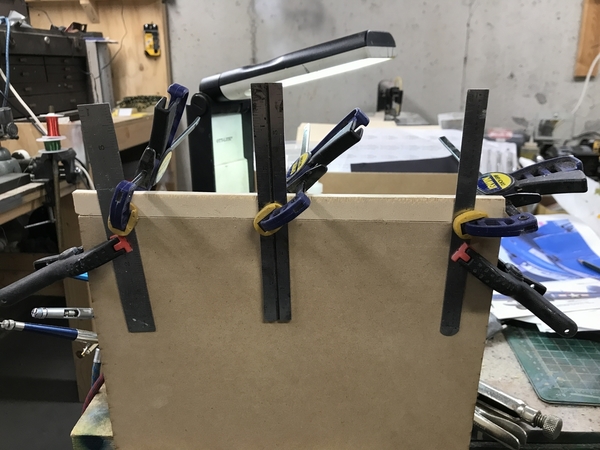
Bronx Board Stretcher Setup

The new height is again correct. Then I put the entire building together with clamps and angle blocks and got ready to mark off the actual amount to remove from the big wall. This image shows the actual overhang that needs removing.
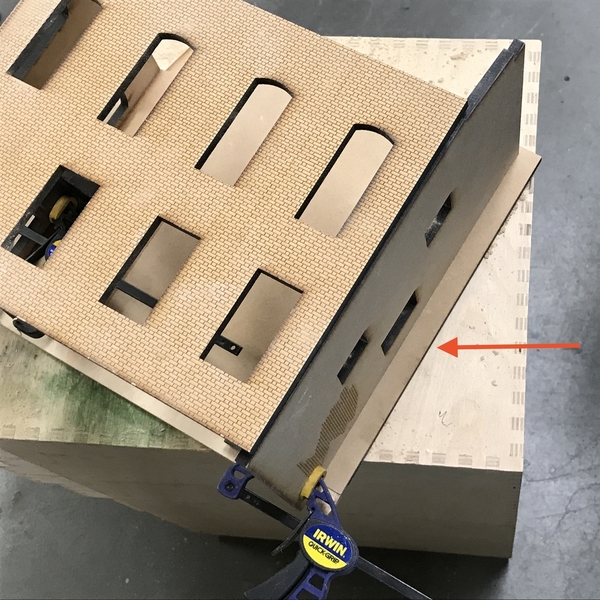
Bronx Big Wall Length Error

So once again, my impatience is my downfall. Maybe not impatience. It just didn't register that I had the wall rotated 90 degrees when I was measuring for the excess. By using a miter at the front corner gives me perfect brick alignment and I don't need a cap strip to high the 1/4" MDF end grain. On the opposite front corner, the front wall overlaps the big side wall and that corner will get filled and made to look like a seamless joint. The back wall goes between the long front and big side wall and it too doesn't involve any brick work. The building's back and side are painted white and I'm assuming to be a cement layer. I've got some exposed brick on the back wall to add interest.

This image shows how the walls fit together.
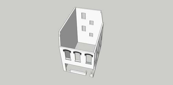
Bronx Modified Assembly

BTW: Here's the Corsair one day from completion. I have to finish the prop, add the antenna wire, and put on the very delicate pitot tube. It was a wonderful model and Tamiya's engineering is stunning. If something doesn't fit perfectly, you've done something wrong. In addition to the engine wiring, I added hydraulic lines in the wing fold and landing gear well areas. The paint is Life Color acrylic, gloss coated for decal application, and then air brushed Tamiya clear flat. The finish came out very nice.
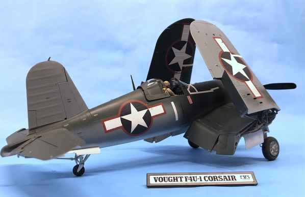
F4U-1A With Bomb 1

The color scheme is early 1943 when the plane wasn't being used on carriers since it had some landing difficulties (which were later corrected). It bounced too much and the pilots had a poor view forward due to the long nose. (Fuel tank is in front of the pilot). To rectify the visibility problem they raised the tail wheel 7 inches and raised the pilot's seat. Tamiya included the taller tail wheel for a different (later) version of this plane.

It's funny, but the F-35C also had similar teething troubles with bouncing on carrier landings and the hook not grabbing the line. Those problems, too, were fixed.

I don't weather my modeling excessively. I just added staining from exhaust and guns, plus some dirt around the landing gear. Corsairs were almost entirely spot welded so there's not much panel detail to add.
F4U-1A With Bomb 2

One more day of work on it and I'll be on Bronx full-time. There's roof filigree that is in the mail to me. Andre cut it over the weekend. Between the architectural details and the roof decor, this building's going to be very special.
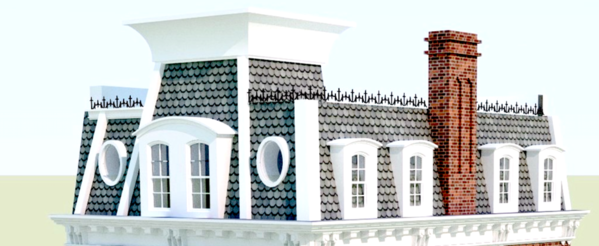
Bronx Filigree


Attachments

Images (10)
  • Bronx Miter Fixture
  • Bronx Miter Shaping
  • Bronx Miter Complete
  • Bronx Board Stretcher Setup
  • Bronx Big Wall Length Error
  • Bronx Modified Assembly
  • F4U-1A With Bomb 1
  • F4U-1A With Bomb 2
  • Bronx Miter Alignment
  • Bronx Filigree
Last edited by Trainman2001

It is one of my favorite aircraft of all time and I too, liked that show. I saw Robert Conrad in a lounge at some airport or another back in the late 80s.

Here's the plane which I completed this afternoon. If you're really interested, here's all the build pics in PhotoImage website, which BTW: is the easiest to use and fastest of all the photo sharing sites I've tried.

https://postimg.cc/gallery/1azqi0zrk/

F4U-1A Final 5

Now back to the Bronx building. I made all the size changes that I've found (so far). Besides the big wall being too long, the 2nd floor was too long and too wide. I hadn't taken into consideration any of the 1/4" wall thicknesses. I then cut it too narrow by one wall thickness (don't have a clue how I blew that one), so I took a piece of my nice German tempered hard board and cut a correct one. BTW; that piece of German stock was used for the fascia boards that I had constructed when the layout was first built in Germany, but didn't get installed until the RR was back in the USA. I don't throw away any wood until it is absolutely unusable. Almost every scrap finds additional use.

I filled the board stretcher section of the big wall, sanded it once and gave it a second coat. I'll finish this up next week.

Bronx Big Wall Filled

After getting everything sized, I used a surface gauge and scribed the 2nd floor location on all four sides and glued on some stops that will hold this floor. I made sure I didn't put them into the corners incase I want to add some corner reinforcements.

Bronx Floor Brackets

Here's the "new" 2nd floor that I had to cut after I over-cut the laser cut one.

Bronx New 2nd Floor

To sand square edges, I mentioned yesterday that I have a tool that I made up to sand perfectly square edges on balsa wood that is butt-glued to make wing skins for large scale RC planes. Here it is. Eventually, you have to replace the sandpaper which is done by removing the clamp screws holding down the sanding fence. It's a 1 X 3 milled trim board screwed to a 1 X 6 base board. The sand paper is wrapped around the 1 X 3's edge and then it screwed down clamping the paper to a square edge. Depending on the grit you choose decides on how fast the stock is removed. I'm using a pretty fine paper. I need this tool since I'm making long cuts with a scroll saw. I keep thinking about getting a small circular saw just to facilitate doing more structure work.

Edge Sanding Tool

I have to decide on what base color I'm going to use for the brick work. I don't want it to look exactly the same as the distillery or Nighthawks, but I have to decide soon since I want to do the brick work before I glue the building together.

And… the "wrought iron" enhancement came from Andre today. They look terrific and will further add to the elegance of this structure. It's cut from laser board which gives great definition and is tough. Much tougher than wood at this gauge. I think I'm going to epoxy some fine brass rods to the tall details every so often to provide pins to affix this to the roof. I should have drawn long tabs on some of them so they could have been laser cut.

Bronx Filigree Laser Cut

I've sort of had a flash of introspection today. I realized that I really am an industrial designer and not an architect or engineer. I think of the finished product and draw it. And I draw it well. But… I don't define how it's all going to fit together. This detail is a perfect example of that. I drew the detail, but left off the means to hold it to the building. Same goes for the how the front window assembly is going to go onto the building. I have all the frames drawn and laser cut, but didn't provide a way to hold them to each other or the building. I'll have to do field mods to accomplish that. I originally went to Michigan State in 1963 to be an Industrial Designer, not an engineer or architect. So I guess I'm being true to myself. I wish I did more planning on the engineering side. It would save me some serious anxiety. I'm not even sure how I want the roof to fit. Should it go down inside the walls or sit on top of them. If it sits on top, it raises the height bit and may confuse how the cornice details are going to install. Get the picture??? When an industrial designer designs a car body, he/she really isn't so concerned about how it is to be made. There may be a feeling about it, but it's not detailed. That's up to the design engineers and then the manufacturing/production engineers to actually build it. That's me!


Attachments

Images (6)
  • F4U-1A Final 5
  • Bronx Big Wall Filled
  • Bronx Floor Brackets
  • Bronx New 2nd Floor
  • Edge Sanding Tool
  • Bronx Filigree Laser Cut
Last edited by Trainman2001

If any of you watch CBS Sunday Morning, the segment on the Bronx Documentation Center and the two photo journalists killed in action, is the very building upon which my compressed version is based. There was a brief image of the building before restoration in the early 90s, and then all the rest were interior shots of the exhibition they're holding for the two men. Quite a coincidence wouldn't you say... 

I know how you feel, but WAB was just getting no worth the effort. It saves me 15 to 30 minutes a day since I don't have to resize the images. When I post on Fine Scale Modeling's site, I have to upload all the pics onto PostImage and then cut and paste the web address of the picture. And it's a pain in the butt, but I can then take the entire thread, pics and all, and cut and paste into WW2aircrafts website, so it's not an extra burden, and I don't have to resize the images into PostImage. I like WW2aircraft since it's a very international group and there's some great European and Australian modelers on it. WAB was the outlier requiring this 2mb and 5 images per post limit. The limit here is 100mb. That's more like it. So… with all that being said, I'm glad you're here to follow along!

Visit to LHS took some of my "work" time today, but I did do some stuff. I moved the Corsair to a lovely showcase at the hobby shop. Scale Reproductions has a lot of very fine models on display from some exceptional builders and I am pleased to among them. I bought some supplies including Tamiya Red Oxide Primer for the brick color. It's a lacquer and goes on easy and dries very fast.

For those of you looking for the December issue of Railroad Model Craftsman which contains the final episode of the Bernheim series, they had a mixup with their printer. Instead of receiving my copy of RMC, I got the December issue of Railfan. And my LHS didn't get their's either. I talked to them today and it's all worked out.

I also printed out some specific details from the SketchUp design for the cornices and corbel arrangements and the storefront. Which brings me to today's challenges. I don't know where my head was when I drew up the front and right hand walls and then had them cut. Everything about the store front window openings were wrong! The right side opening was way to low and the lower lip was too low also. The intermediate pieces that make up the lower sill were correct but there weren't enough of them. The main window opening on the front wall was too high.

So I had to cut here and pack out there which took most of the 2 hours that I was working. 

I did spray the red oxide, probably prematurely, since I then had to start gluing and hacking to change the shapes of those openings and the paint got a little banged up. I'll go back and do it again after the front two walls are joined. I built up the low places using various thicknesses of ply and basswood strips so the front and side wall sill and openings were exactly the same. I also finished filling the extended edge on the big back side wall. The repair will be totally invisible.

In this image, the walls are matched on their top sides and are in an upside down position. I'm not worried about the missing bricks on the lower portion since this is covered by the simulated etched tile facing. All the rest of these fixes will be hid by layers of paneling and cornices.

BB Fixing Window Opening

I also had to modify and add pieces to the lower sill pieces that will be affixed to the base board.

BB Corrections cont

I just went back and actually spent some time moving all the pieces around in CorelDraw to see why I blew the measurements so bad. There are more corrections coming based on that analysis. The doors and windows added together from left to right seem to extend out past the building's envelop. I will need to correct that. I may end up scratch building one or more of the front windows to get it all correct. If I need to I can remove a little stock from that brick edge of the left side, but I'd rather not.

For some reason, I thought that the lower sill on the right side wall needed to extend out past the building's corner. Now that I went back and looked more closely at the SketchUp drawing I find that this isn't correct either and I will trim it back to match the building corner above it.

So what happened? I neglected to build the model in CorelDraw. I did this with Nighthawks, which was not laser cut, but neglected to do so with this building. If I had done so by moving the pieces into contact with each other, I would have immediately seen that it wasn't adding up. Eventually, I will figure out how to do this BEFORE I spend $$$ getting it laser cut. Again, the laser is stupid and only does explicitly what I tell it to do.

Here's one of the detail images sitting on my workbench.

BB My Plans

Work will continue tomorrow getting it all correct.

Attachments

Images (3)
  • BB Fixing Window Opening
  • BB Corrections cont
  • BB My Plans

I'm so glad it was so relaxing for you! 

We had lunch out with our daughter today so I didn't get to "work" until 3:00. I am still adjusting the lengths and widths of these _Y%@_ walls and floors. I am nonplused that I got so many of them wrong. I don't know what I was thinking. The big wall was still too long. All the floors and ceilings were wrong. Luckily they were long, not short. Nothing appears to have been short. But the changes were made and I was able to get the walls glued together.

I went back to SketchUp and spent more time working on the store front especially paying attention to how the windows will be fit together and learning more about the cornices. 

I glued the miter walls and the big walls as two separate items, and then after they were set, joined them together.

I have a picture frame clamp that I used for one edge, and the corner clamps for the other end when possible. The big walls are one story higher than the brick walls so the corner clamps can't be used for that joint. I also employed some machinists angle blocks and big Quickie Clamps to squeeze it all together.

This picture shows the clamping and the Quickie clamps. I too care to get the edges to coincide and when I pulled it from the clamps I added filler to that edge. I want that edge to disappear. You can see the completely filled lower edge that was finish sanded yesterday.

BB Big Walls Glue

The miter corner was held with a corner clamp on top and an angle block and small Quickie clamps.

BB Miter Wall Glue

All these joints have a bit of thin CA run down them to add to the strength and provide additional holding while the Titebond II glue sets up. It lets me unclamp sooner.

BB Miter Wall Glue 2

I put the four walls together again using various clamping schemes, and this is drying overnight. I think I would have had less tumult with the building in its original size. It was when I cut it down that I started losing control of the fits.

BB All Walls Glued

The difficulty with laser cutting bricks into MDF is the fragility at the extremes of the miter. You can see that some bricks have broken away. It's just a thin layer. I'm going to attempt to fill the gaps and re-scribe the mortar lines after the fix is made.


Attachments

Images (4)
  • BB Big Walls Glue
  • BB Miter Wall Glue
  • BB Miter Wall Glue 2
  • BB All Walls Glued

Thank you for that fine comment!

Building came out of the clamps within about 2mm of perfectly square. The first floor plate fits a bit tight at the front, but works. I'm going to have to modify the big front windows. Based on my test fitting of the two front doors, the center window is about 1/8" wide. I may end up scratch-building a new window. I made a new little right hand front piece since the lower wall on right side was still protruding out past the building line. I cut it back (with a miter to complicate things a bit) made a new piece that mates with the miter and bends 90° back towards the doorway. The floor plate extends past the door to form a small step so the return piece needed to be 1 floor-plate-thickness shorter than the front wall.

I attempted to fill the broken brick work at the mitered corner and when dry, used a micro razor saw to re-scribe the mortar lines. I then shot it again with the Tamiya Red Oxide Primer.

BB Corner Repaint

I sanded and filled all the flush joints formed between the left side and back walls. I then filled these with Squadron and then Tamiya solvent-based model fillers. When dried I sanded them flush. Those joints will be very hard to see.

The slant portion of the blank walls has a step that should line up with the tops of the bricked walls. In the front left corner, the step was a bit high so I took a diamond file and leveled it. The one at the back right corner was a little bit low so I filled it with UV-cured (Bondic) resin and filed it level also.

BB Back Edge Trued

It's easiest to do the mortar application when the walls are as bare as possible, so it was time to do it NOW. I use drywall joint compound and have described this in several buildings before on this thread, but each time I do it I refine my process. I just smear a little pile on various parts of the wall, section at a time, and squeegee it off with, in this case, I piece of light ply that has a nice straight edge. I then go back and use a single-edged razor blade to scrape off the rest of the excess.

I force dry it with the hot air gun and then take a damp paper towel to wipe off the film that remains behind. I will probably do this again tomorrow after it dries some more. Instead of using an alcohol or other wash on the bricks, this time I'm going to seal it will matte lacquer. I don't want this building's brick aged too much. I want it to look like it was recently restored.

I started the mortaring with the little bit of exposed bricks that I had etched into the back wall. I wanted to test using the ply and razor combo to scrape it clean. I'm going to paint the blank walls an antique white.

BB Rear World Bricks

I then did the big side wall and finally the front wall. I do need to retouch the broken bricks that didn't get fully repaired.

BB Mortar Joints

I couldn't help but put that eyebrow over the window to again see how cool it looks. All that patch lumber over the window area gets completely covered up with some complex trim. These two pics show that pesky little extension that sticks out of the lower corner of the right side wall. It was that piece that needed to be cut back. Again, I'm not sure why I thought that had to protrude past the building line.

I wish I had the patience or steady hands to paint the inward facing bricks a dark purple color to make them stand out. I've seen this brick pattern when they use contrasting colors. It would be a pain-staking job and I should have done it before mortaring.

BB Front Mortar

Here's a detail shot of what that cornice work is going to look like.

BB Lower Cornice profile


Attachments

Images (6)
  • BB Corner Repaint
  • BB Back Edge Trued
  • BB Rear World Bricks
  • BB Mortar Joints
  • BB Front Mortar
  • BB Lower Cornice profile

Thanks for the nice comments about the Corsair and the BB (Bronx Building). With the Corsair safely in the display case at the hobby shop, I won't be able to break it by picking it up all the time to look at it.

Short session today. I touched up the brick corners and, while they're fixed, they could be better. I put a coat of fixative to stabilize the paint and mortar in case I want to add additional weathering. Incidentally, looking more closely at the prototype, the brick work has a lot of variability. Almost anything goes. I then brush painted Apple Barrel antique white craft acrylics on the two non-brick sides. The corner seams are effectively invisible. The antique white gives a good stucco feel.

BB Back Wall Painted

The building lacks a back door. I think I may cut one in the back corner of the big blank wall which will be the place where the dumpster or trash containers will go.

BB Big Blank Wall PaintedBB Brick Corner TouchUp

I also have a hankering to design some 0'Scale kitchen appliances of the 1950s variety to have 3D printed by Rusty Stumps and populate the appliance store which I bought as a prebuilt building when Frank Miller broke up his railroad 10 years ago. I already have the flashing Zenith TV sign from Miller Engineering that I bought years ago at York.

Attachments

Images (3)
  • BB  Back Wall Painted
  • BB Big Blank Wall Painted
  • BB Brick Corner TouchUp
Last edited by Trainman2001

Spent the session today fiddling with floors and the mansard pieces. Everything needed adjusting, but in the end I think I've got it where I want it. I forgot to have the upper roof cut so I made it out of 1/8" Masonite after I fit the front and side Mansard pieces to figure where the intersection points would be. My cut got a bit undersized, but it will not show and I'll be able to correct it moving one.

For the attic floor I needed some ledges to support it. I drew a line around the back two walls with the digital calipers and then moved that line down the thickness of the attic floor and scribed another line. It was this second line that the ledges were aligned with. I use Aleen's and then follow up with thin CA since it was difficult to clamp. I always have to check myself that I'm accounting for material thicknesses when putting stuff together. If you want the top edge aligned with something, you'd better put your glue line below that one material thickness. It's easy to forget.

BB Sub Roof Ledges

The attic floor was laser cut and needed some slight mods including changing the position of the opening for the tower. Again I had to ADD wood where it was missing. I'm getting good at this…too good! This piece now fits like a glove.

BB Sub Roof Fit

At first I thought the front Mansard was butting up to the left side and mounted a bracket to support it, one ply thickness behind the end. After fitting it, I realized that the Mansard sits in front of the slant roof edge and goes to the extreme left edge. So I popped that bracket off and found I no longer needed it since there's sufficient glue surface on the wall edge. Notice the angle I sanded onto the lower lugs that support the bottom Mansard edge. I set the belt sander table to the mansard angle and sanded the square stock so it gives good glue surface.

BB Lug Profiles

The side Mansard is a flimsy piece so I need lugs on the attic floor and lugs on the top edge to support the top roof. When it's glued together it will be very sound.

BB Lower Roof Mansard Lugs

To support the top roof again I needed ledges on the back two walls and lugs on the tops of the Mansard walls.

BB Side Mansard Roof lugs

The top roof fits okay, but there are gaps on the front and side. The building is slightly out of square. It only shows up when I'm trying to fit a square piece into it. I had to adjust and adjusted too far. If this fit was critical, I'd make a new piece, but it's all going to be covered with "tar paper" so if I use some scrap to fill any gaps, it will all be okay.

BB Upper Roof fitting

All of these parts are just sitting there since nothing can be glued in up top until interior details are addressed. I'm thinking of making the first floor an art gallery like the prototype is and I'm designing the partitions for the insides. I want to fit all that and the lighting before gluing anything together. I can make it so the first floor pushes up from the bottom, but the ceiling lighting needs to be done. Hmmmm…. I could make the base and the first floor ceiling push up from the bottom. It would remove the need for floor ledges. I would have to break them out or have the first floor ceiling 1/8" lower. In that way, I can finish up all the wall work on the upper floors. I want to put on the fish scale shingles BEFORE the walls are glue in since it would much easier doing that while they're flat.

As I've said before: With scratch-building a unique structure, there's no fancy instruction book. You're writing it as you go. I have to keep doing things in my mind to figure out what goes before what.


Attachments

Images (6)
  • BB Sub Roof Fit
  • BB Lug Profiles
  • BB Lower Roof Mansard Lugs
  • BB Side Mansard Roof lugs
  • BB Sub Roof Ledges
  • BB Upper Roof fitting

"As I've said before: With scratch-building a unique structure, there's no fancy instruction book. You're writing it as you go. I have to keep doing things in my mind to figure out what goes before what."

So true.  You can't think of everything until you encounter it!  However, experience has given you the knowledge to hold back gluing until everything is in.  Just with the parts sitting there, we get a good feel for the bulk of the finished building!  Looks great!

Myles, I would like to digress a moment to the Bernheim Distillery articles.  I just finished the third article.  I missed the second, so I will have to look for a back issue.  Excellent work as I expected!

I would like to make a couple comments.  First, I appreciate what you wrote on page 35, "I quickly developed enormous respect for the kit makers out there...Anytime a part didn't fit, it was not the cutters fault; it was the designer's."  How true!  Perhaps we have gotten to the point of taking laser cut kits for granted to some extent.

Second, the last sentence on page 43, "Combining good modeling skills with the ability to design buildings makes for some great modeling fun!"  I think you did all RMC readers a great service showing how the design software tools can make for some great modeling.  Yet old tried and true tools, materials, and methods still come into use on this kind of modeling!

Congratulations of getting the articles published!!  Thank you!

Mark, believe it or not, I still haven't received either my subscription copy or the author's copies, so other than the original PDF sent to me back in the beginning of November, I haven't seen Part 3 in print. I did get paid, so I can't complain too much. Their printer accidentally sent the wrong magazines to the wrong subscribers. I got an unsolicited copy of Railfan, which is also a White River Productions mag. And I thank you for your thoughtful review. You get an "A" on you book report.

And thanks to all the other fellas that have commented recently. It definitely keeps me going.

My persistence (not patience) was in full display today when I made a new roof that would fit better. Of course I measured the length from the wrong point and this second attempt was about 3/8's too short. I added a chunk of Masonite with a  bit of lateral reinforcement with some thin ply and then cut it to the RIGHT length. I still needed a little added filler strip on the rear right corner so the side Mansard made full contact with the roof without any distortion. The roof forms a critical part of the support for both Mansard pieces.

And I finally figured out where the front Mansard roof piece actually goes. It took me three tries to get this right! The way I was previously going to glue it on put the front double-windowed gable way off center. It just wasn't right. I needed to move it right one wall thickness and then remove that same amount from its right end. I needed to add a filler piece on the left so that roof would lie flush all the way to the extremes. The arrow shows the added repair piece. Also, the oval windows now sort of line up with the windows below. I don't know why I had the hole cut in the sub-roof. It serves no purpose and I probably should fill it.

BB Front Mansard Fix

I explored the idea of loading the base and first floors from the bottom, but it really won't work for various reasons, so I to started constructing the interior since it has to go in before all the upper floors. It's going to be an art gallery and I'm probably going to plaster the walls with an eclectic mix of Edward Hopper paintings and PRR railroad art by Grif Teller. It's my gallery and I can put whatever art in it that I want.

I designed the partitions on SketchUp just to get an idea about fit. I made the aisle ways 5 scale feet wide. Each area will be illuminated. I made the partition height just a skoosh lower than the ceiling so they wouldn't interfere.

The let hand partition separates the stairway from the rest of the building. I'm making the left door access the 2nd floor. Unlike Nighthawks, this building does have enough room for inside stairs. I haven't provided any provision to get to the attic yet. I may or may not… depends on how I feel. If they're left as dark spaces, stairs are redundant. The front low wall is just sitting there for test. I still deciding whether or not to actually build a stair. I don't think I'm going to illuminate the 2nd floor.

BB Stair Partition

All the partitions are held together with thin and medium CA. I used the corner clamps to hold the pieces for gluing, trying to be careful not to glue the clamp to the work piece. I had a left over Tichy door which I inserted in a cutout on that end piece. This is a door to a rest room and access to the back door of the building which I'm going to add at the rear corner of the big blank wall. The big partition is glued down, but the others are not…yet. I want to paint them, add flooring, and put the pictures on the wall before gluing them down. I am NOT going to use that checkered floor that I used in Nighthawks. I had just realized that the same checkered pattern is in Nighthawks, Saulenas, and the Chocolate Shoppe. It's also the floor in the boiler plant. This building should have Parquet. I have some that I used in the Victorian Train Station.

BB Interior Wall Arrangement

I traced these walls on the ceiling so I could lay down the circuit pattern for the LED lighting. I then put the copper in place and cut the circuit gaps where the LEDs will be soldered. I'll do this tomorrow. The arrows show the circuit cuts. I wanted to limit the LEDs to 4 since I'm using a 12VDC source with a CL2N LED driver. Each LED drops 3 volts. The strip without the light is facing the big windows.

BB Lighting Circuit

Some other news: I wanted to get some small 1:48 major home appliances 3D printed by Rusty Stumps. I want to use them to populate an appliance store for the one building that I bought complete. I already have the neon Miller Engineering Zenith sign. I downloaded an array of appliances from the SketchUp 3D warehouse and sized them to 1:48 and sent them to Walt Gillespie. Well… the drawings were not done well and needed a lot of fixing before they could be printed. Walt uses a laser resin system which produces very fine high res output. After we got all the drawing fixed, he let me know what it was going to cost. A fortune! It was going to cost a fortune! The resin is $175 a liter and O'scale appliances are actually bigger than you think when you printing 30 of them. I ended up killing the deal and he's going to see if a friend can do them on a filament printer. I may check with Shapeways also. Then there's plan C: making them out of styrene by hand. I previously had downloaded and sized a bunch of Google-searched images that I could use as facings for handmade blocks and I might still do that.

Next: I'm putting the finishing touches on an article about Nighthawks. Like Bernheim, Nighthawks presented some new techniques and learnings so it could be a nice article.


Attachments

Images (4)
  • BB Front Mansard Fix
  • BB Stair Partition
  • BB Interior Wall Arrangement
  • BB Lighting Circuit

I designed the painting for the art gallery. Then found out that our Canon Pixma MX870 Inkjet Printer no longer feels like printing yellow. So the images were basically unusable. I changed cartridges (although yellow was half full) and it was still not printing. Did a deep cleaning and no yellow. I'm left with two choices: pull the print head and attempt to clean it, or buy a new inkjet. Anyone have any good recommendations for a modestly priced, good-print-quality machine that can scan and fax (although I don't use either function very often)?

So… this meant that unless I find another approach to doing the interior, I'm hung up. I re-assessed putting the base and 2nd floor in from the bottom, and found that it would work. This frees me up to work on the entire top areas, windows, etc., and put the interior in bottom-up when I'm ready to do so. I removed the 2nd floor ledges since the 2nd floor will now be glued directly on top of the first floor walls.

I then got to work on the ceiling lighting. The steps to work with the surface mount LEDs are:

  1. Test each individually using a power source with the appropriate current limiting resistor on either the positive or negative lead. (the LED calculator shows the limiter on the negative side). You need to do this test since these tiny 3.3mm X 2.7mm packages are easy to kill and you need to know if the circuit doesn't work, that you did something on assembly and not that you had a bum LED in the first place.
  2. Tin the two opposing sides of each gap you cut in the copper foil. You can be a little generous here, but not too generous. 
  3. Mark which direction is + and -. Place the LED across the gap sitting on the solder with the narrow + side facing  the + end of the circuit and gently hold it there with the tip of a tweezers.
  4. While holding the LED in position, heat the foil adjacent to the LED and as soon as the tinning melts and the LED settles into it on that side, pull off the iron. Don't wait around! The LED will be destroyed with too much heat.
  5. Still providing some light pressure on the LED, heat the other side foil and do the same thing once the puddle melts.
  6. Using your test leads, put the + on one side of the LED foil and the - on the other and see if it lights. If it does, move on to the next LED.
  7. If it doesn't you killed it when soldering. De-solder it and get another one.

BB Lighting 4 Array

At the start of the circuit I soldered the CL2N3 LED driver chip. The first one worked for a bit and then stopped, so I got another one. This worked okay so I did wired in the power leads. I brought them up to the ceiling, through two holes, and then back down into the holes. You're looking at the ceiling upside down. 

This is the first driver I installed. Didn't like how I did it, so when I replaced it I didn't bring it through the holes, but did all the soldering on the ceiling's face. This part of the ceiling will be out of sight in the back of the windowless side of the building.

BB CL2N3 Driver

I assembled the walls and ceiling to see what the light level is. My first test had 4 LEDS in the array since I wasn't sure about driving 5 with a 12 VDC source.

BB Main Room 4 Lights

I didn't like that shadow cast by the mid-room partition so I cut one more gap and installed a 5th LED. It drove fine with the 12 Volts and eliminated the shadow.

BB Main Room Lights

Then the lights went out. When I tested each LED they all seemed to work, but not collectively. Then I noticed that LED #1 was intermittent. The solder joint underneath was not very good and it needed retouching. Then when I retested my lights were distinctly dimmer verging on yellow. What happened? I thought that maybe 12v was really NOT enough.

I went into my electrics box and found two 19 volt computer power supplies, one Apple and one HP. I cut off their ends and prepared them to drive my circuit. Remember: The CL2N3 driver doesn't care what the voltage is between 5 and 90, it just puts out 20ma to drive LEDs. The Apple power supply produced no voltage. I wonder if it's regulated in someway that it doesn't produce power unless the load is a computer battery. Any ideas?

The HP supply produced a steady 19.5 volts so I hooked it to the circuit which lit momentarily and then died. Again, I checked each LED and suspected that something happened to the driver so I replaced it. I also killed an LED when I accidentally connected my direct voltage lead to it and not the one protected with the 470 ohm resistor. So I replaced that one too.

I didn't want to use that heavy unit again so I went back to the 12v unit and guess what? All the lights were bright. I suspect that the poor solder joint was limiting the voltage in the circuit before.

Here's an upshot showing the lights all lit.

BB Main Room Lights Upshot

With the lighting working, I shot the walls with a coat of Tamiya Gray primer, masked the LEDs and sprayed that surface also, and then hand brushed three coats of antique white on the ceiling. It's now done and will wait for the rest of the interior to be finished including putting artwork on the walls and something on the floors. I might make the floors bare concrete with is used in lots of restored buildings like this one. There's a bit of electrical tape protecting the Driver and I put a small cable tie underneath as a strain relief. I also tie a know in the cable where it exits the floor to act as an additional strain relief.

BB Painted Ceiling

Depending on when I get the new printer will determine when the interior is finished. So I'll be working up top for a while. At the end of the week we're heading back East for the Holidays. And on Thursday, I have a stress test and echo cardiogram to get a better idea why this Afib is being so stubborn.


Attachments

Images (6)
  • BB Lighting 4 Array
  • BB CL2N3 Driver
  • BB Main Room 4 Lights
  • BB Main Room Lights
  • BB Main Room Lights Upshot
  • BB Painted Ceiling

Got a new printer today. It's an HP Envy Photo Printer 7858. Costco had this $180 printer for $80. Couldn't resist. I bought a two-pack of the additional printer cartridges. Unlike Canon, where the print jets are part of the machine and you replace an ink reservoir, HP's nozzles are integral with the ink reservoir so you get new jets each time you replace the cartridge. That should solve the clogged jet problem that trashed my Canon printer. The cartridges are move expensive due to this added technology. Also, the color inks are all in the same cartridge, so when one color runs out, you've got to replace the entire cartridge. I looked at the Epson with its oversized ink reservoirs that you fill from a bottle of ink, but the printer, even though you save a fortune on ink cartridges, was 3X more expensive than comparable HPs. Furthermore; I really could imagine making one heck of a mess refilling with those bottles. I read a lot of reviews and some folks said it wasn't as convenient as Epson made it seem. The new printer has a fax and copier. The fax is a non-starter since we know longer have a land line to which to connect it. It was a snap to get installed and immediately found both of our laptops and I was printing with it in 10 minutes.

And I printed the artwork in full color. My first set of images was too big. The paintings came out to almost 6 scale feet wide in some cases. I could only get three on the biggest wall, and on the partition walls, one or none. You'll notice that I painted the walls a sort of yellow green pastel shade and mixed up some concrete color for the floor. The floor is no where near as dark as it's showing in the picture.

BB Big Art

I air brushed the walls and brush painted the floor since I didn't feel like masking and the concrete didn't need to be as smooth as the floors.

With the smaller art work, I think the wall looks more like a modest art gallery. I think I'll add a baseboard to clean up the wall/floor interface. I also prepared some graphics that I think I turn into decals to apply to the walls and store front. That wall is 11 scale feet high So the pictures are about eye level to an O'scale person.

BB Resized Art 2

Tomorrow is cardiac care day with my echo cardiogram and stress test to see about the Afib. Depending on how all that goes, I may or may not get into the shop. If I don't, that will be all the work until after New Years, since we're leaving on a holiday trip on Friday. And if I don't post, everyone have a safe, healthy and merry Christmas and New Years.


Attachments

Images (2)
  • BB Big Art
  • BB Resized Art 2

Looks great as always, and I hope the tests goes well.  The stress test was my least favorite of them all, and I was running quite a bit when I had mine.  Hopefully they can get some solutions after the tests for the Afib.  My end result was an ablation, and its worked well for the last two years for me.  If you ever need to compare afib notes, get a hold of me.  

Thanks for the kind thoughts. The tests this morning went okay as far as I can tell. Instead of the treadmill, the nurse changed plans and did it chemically. My AFib pulse was randomly varying from 80 to 120 BPM, and she felt that it was not wise since they wouldn't be able to control the end point on the mill. The chemical method is just plain weird. It makes you feel very loopy, but it only lasts 4 minutes and then they shoot you with the antidote. I still feel out of sorts. I hope tomorrow I will feel normal. We're not leaving for Philly until Saturday. I asked if they found anything really bad what happens? They told if they saw something really bad, they take you upstairs and schedule and intervention. Since I was not taken upstairs I am assuming that nothing acute was found. But I won't hear the results for 4-5 days and that doesn't include the holidays. Patience...
When I got back, I finally ate and then rested a bit… and then I GOT TO WORK!

The interior of the gallery is as finished as it's going to get. I will still add some museum goers before I button it up. I created a decal for the graphics, and used a new product (for me) Testor's Decal Coating Spray. It was easier to use than the hand-brushed MicroScale Liquid Decal Film. I made two different sizes of graphics so I had a choice to use for the building.

BB Decal Sheet

The Woodbourne labels will be used in the front windows or on the exterior trim.

I sprayed part of the wall where the decal would go with some gloss clear to prepare the surface for the decal. I, of course, decided to touch it to see if it was dry. AND IT WASN'T, and I put a big ugly fingerprint on it. When I force dried it completely, I sanded the blemish, resprayed the yellow, force dried it again, and re-sprayed the clear. This time I was more judicious in the amount of coating I sprayed. 

It was time to cut out all the artwork, coated the back with a thin coating of Pressure Sensitive Adhesive and mounted them on the wall. I had previously marked the 4 scale feet from the floor as a reference line. 
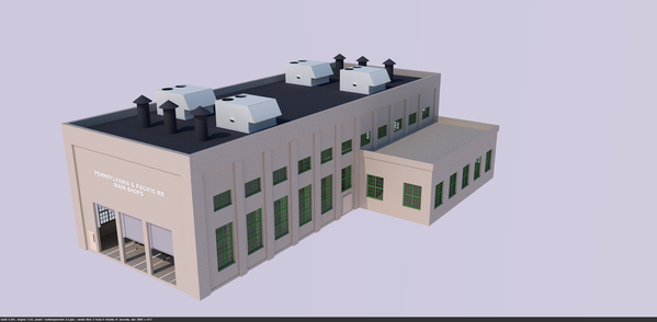
After mounting the pictures, I placed the decal, and when dry, brush-coated it and the adjacent area with Tamiya Flat Clear to kill the shine and blend the decal in a bit. This picture was BEFORE the flat clear was applied.

BB Gallery Decal

I added some baseboard on the back wall and trimmed around the door. I held the trim with PSA and reinforced with CA. For the small pieces I used thick CA. I then glued the partition walls in place with some old Henkel polyurethane cement. I then plopped the ceiling on for this next series. Next session (tomorrow?) I will add the folks and then glue on the ceiling.

BB Gallery 1

BB Gallery 3

BB Gallery 2

I'll put it in the building tomorrow and take some pictures through the windows which will give a more realistic view.

I had thought we were getting on the road tomorrow. I was mistaken. We're leaving on Saturday, so tomorrow is another possible building day.

Attachments

Images (5)
  • BB Decal Sheet
  • BB Gallery Decal
  • BB Gallery 1
  • BB Gallery 3
  • BB Gallery 2

Thanks Mark! I think you hit the nail on the head. I just finished writing up the article on Nighthawks. It's about the same length as Bernheim was. I haven't submitted it yet and RMC has already told me that, while, they'll print whatever I write, it won't be consecutive… got to give others a chance to get in line  But, what you're saying is what I'm feeling. Each project to be worthy of dissemination to others needs to be unique. It has to offer something that's not readily done by the modeling public. There are many, many articles on building sheds using clapboard siding, so to stand out, it has to be different. So… I've set the bar pretty high for myself. Bernheim dealt with design for laser cutting. Nighthawks has interpreting a work of art into a 3D model, dealing with conical turrets, curving a plexiglass window, etc. Bronx Building again, deals with more on laser cutting design, capturing details about an existing building using Google Earth, making a passable art gallery using images and frames downloaded from the Internet, plus more on working with complex Mansard 2nd Empire designs. So… what's next? I have two interesting ones in the wings.

1) Rick House (bourbon aging warehouse) under construction to go across the street from the distillery. Rick Houses with their skins on are just plain boring — a box with a peaked roof and lots of small windows — but under construction it's a labyrinth of different sizes and lengths of wooden beams. I have some good sources to create a realistic, albeit compressed version of one of the most elemental processes in the bourbon business. This would also give my great Grove heavy lift hydraulic crane something useful to do.

Rick House Construction Render

2) The 40" engine house. Again, engine houses are not unique, but building one with a scale replica of a 100 ton gantry crane inside might up the ante a bit. I really need to get cracking on this anyway since it's one of the barest places on the entire layout. It's been waiting for a long time for this structure. Also, I have the resources to do it with my publishing money. I'm limited with service decks inside due to the tight 3.5 C-to-C track spacing resulting from laddering Ross #4 switches.

3d Engine House Ver 5~ 2016-12-02 21054500000

Making long inspection pits is difficult with 3 rail track. I've seen using tensioned copper wire to make a barely visible conductor. My design includes the buttresses to support the gantry and it's associated girders.

 3d Engine House Ver 5~~ 2017-01-26 18172700000

So there you have it. First things first. Finish Bronx!

Attachments

Images (3)
  • Rick House Construction Render
  • 3d Engine House Ver 5~ 2016-12-02 21054500000
  • 3d Engine House Ver 5~~ 2017-01-26 18172700000
Last edited by Trainman2001

They have to wait for two projects: I will finish the Bronx building and then I may be building another 1:32 aircraft (a Trumpeter F-105 Thunderchief) on commission. I kind of like do a structure then a complex plastic kit and then another structure and so on. It reduces any tendency for boredom.

I got the gallery populated today. I had a set of already painted Woodland Scenics folks that looked like gallery people and then I painted two more characters that were from a Preiser set. They're a tad weird and definitely European, but the man and child also made passable gallery goers. It took me well over an hour to paint them.

BB Gallery Populated 1

Should have taken the time to paint the white edges of the photos. Thought about it, but didn't do it. When they're inclosed in the building, the viewing angles are very restricted so you won't see much anyway. It's just giving the impression of an art gallery that I'm looking for.

BB Gallery Populated 2

I decided that instead of gluing the main floor into place and making removal impossible, I drilled and used some small brass screws (German) that hold it at four corners. I used thin CA to harden the screw holes and threads since MDF is notoriously bad at holding screws. I'll probably paint them brick color so they'll be less obvious.

BB Mechanical Floor Connection

I started assembly of the front supports for the windows by gluing them to the base plate only. I figure that I can't completely join the windows, base and main building together or I wouldn't be able to ever remove the interior. I can only make it removable (thus the screws) if I manage to keep them segregated. This will take more attention on my part, something of which I am often not so good at.

At this point I felt it was safe to actually glue the ceiling to the gallery walls, but not the building itself. So the entire gallery is removable as one piece. I used a heavy angle block as a gravity clamp while the Aleen's dried.

BB Ceiling Glued in Place

I removed the interior, hardened the screw holes, painted the remaining walls in the gallery the light green mixture, and then added a baseboard on the front wall that was 1 base-plate-distance off the bottom. I left the interior out of the building for the time being as I start working on the 1st and 2nd floor windows which are easier to install when you have unfettered access.

I sprayed the window frames while in the frets first with Tamiya gray primer rattle can and then with Tamiya flat white from the air brush.

Speaking of air brushes. Several months ago, I sprung for some inexpensive Chinese air brushes from a brand called Point Zero. The were very inexpensive, $33 for two brushes: a bottom feed double-acting brush with a glass bottle and siphon cap, and a double-acting top feed detail brush. While they seemed to be well made with all the parts that a Badger or Pasche would have, they weren't worth the money I paid for them!

The siphon feed brush sputtered and never sprayed properly. Both brushes use O-rings for seals in the various parts, and these rings ARE NOT COMPATIBLE WITH ACETONE! In order to do a deep cleaning with acrylics, which no matter how hard you try will build up inside in low pressure areas, you start with iso alcohol, but inevitably, you end up with acetone which dissolves the dried acrylic. And then it dissolves the O-rings and turns the air brush into junk. Meanwhile, I have a Badger 150 that I bought in 1973, that was rebuilt for free several years ago (Lifetime Guarantee), and works like a charm. Badger has one teflon ring that seals the needle that's impervious to any solvent. So I went to the LHS and bought a Badger 200 single-action, top feed detail gun that's made in the USA. You get what you pay for!

There's lots of extra windows since I I didn't change this fret too much when I compressed the building so I have some extras.

BB Painting Windows

So… that's the last post of 2018. I'll see y'all back here in 2019 for more exciting building fun. When I get back I'll be building windows, and then crafting all those wonderful architectural details and cornices. I'm looking forward to that part.

BTW: still haven't received my December RMC with Part 3 of my article and didn't receive December's author's copies either. Annoying! They had a real screwup with their printing contractor and it doesn't seem to be corrected yet.

Everyone have a Merry Christmas and a Happy and Healthy New Year!

Attachments

Images (5)
  • BB Gallery Populated 1
  • BB Gallery Populated 2
  • BB Mechanical Floor Connection
  • BB Ceiling Glued in Place
  • BB Painting Windows

Add Reply

Post

OGR Publishing, Inc., 1310 Eastside Centre Ct, Suite 6, Mountain Home, AR 72653
800-980-OGRR (6477)
www.ogaugerr.com

×
×
×
×
Link copied to your clipboard.
×
×