
Diode replacement:
(I don't claim to be an electronics wiz)
Diagnostics:
1. VAR 1 input was throwing the circuit breaker (CB) on my 180 watt Lionel 'brick'(power supply).
2. insured the input power supply was in phase with other power supplies.
3. removed output wire on VAR 1 and still threw the CB.
4. Tried another input power supply to VAR 1 and still threw the CB.
5. Called MTH tech and he said it was probably the surge suppressor.
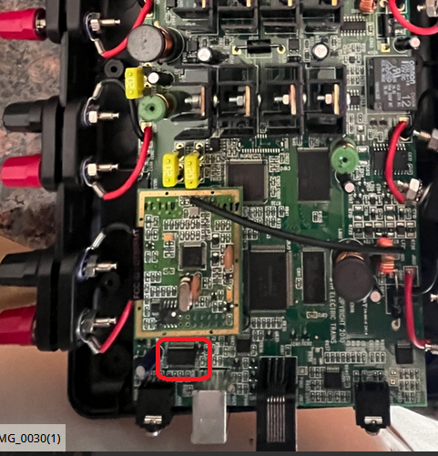
The surge suppressor is a diode (part #BB-0000033 at $3.60 each: got two since cheap and min order of 10 bucks).
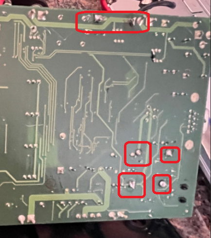
The VAR 1 diode is the far corner one by the VAR 1 output plugs (each output has a diode).
Replacement:
1. removed the 6 screws on the bottom to release the top of the case (insure power is off).
2. Removed the suspect diode and put my volt meter on R and checked the suspect diode and the needle pegged to the right whereas the new diode stayed to the left.
3. Bent the new diode wires to align with the holes and cut off the excess wire.
4. Used some fine needle nose pliers to hold one wire (and also act as a heat sink) and soldered one side (did the same to the other side).
5. Tested and all is 'good in the world' again.

Note: I put the diode in with the marking on one end of the diode facing left (same as the other good diodes).
Interesting: diodes only allow 'juice' to flow one way but the new diode would not allow voltage (tested via the volt meter on R) to flow either way! The damaged one pegged the needle to the right in both directions.

TIUDIODEreplacement01

TIUDIODEreplacement02

Attachments

Images (2)
  • TIUDIODEreplacement01
  • TIUDIODEreplacement02
Last edited by samparfitt
Original Post

Replies sorted oldest to newest

That is a bi directional TVS diode since it is on a AC line.  A TVS is a special diode that doesn't allow current flow in either direction until it hits a breakdown voltage.  It is used to clamp a voltage spike.  When damaged it can short, and since it is on the AC line and a short it reflect back to your transformer.


All the versions have it that I have seen.  G

Penn-pacific:

I had to do some research to find out about TIU versions.  Per the manual I should be able to find out the version via the remote: when accessing the TIU, it showed no version so I'm assuming it is the first version (especially since I got the TIU when it was first available).


GGG,

I was hoping someone would explain the diode, so you confirmed what I thought:  the diode can be put in either way (ie bi directional as you mentioned).  Thanks.

Last edited by samparfitt

Hi,

I followed the earlier post and changed the diode with the recommended one from digikey, part number below. But var 1 is still shorting out, when I remove the diode and apply power it does not short out and I am getting the same voltage at both input and output. Any suggestions?

PART: 1.5KE36A-E3/54GICT-ND
MFG : VISHAY GENERAL SEMICONDUCTOR - DIODES DIVISION (VA) / 1.5KE36A-E3/54
DESC: TVS DIODE 30.8VWM 49.9VC 1.5KE 0.74000 2.96
COO : CHINA ECCN: EAR99 HTSUS: 8541.10.0080
ROHS3 COMP REACH UNAFFECTED 12-JAN-2017

Thanks

@ErnieM posted:

Hi,

I followed the earlier post and changed the diode with the recommended one from digikey, part number below. But var 1 is still shorting out, when I remove the diode and apply power it does not short out and I am getting the same voltage at both input and output. Any suggestions?

PART: 1.5KE36A-E3/54GICT-ND
MFG : VISHAY GENERAL SEMICONDUCTOR - DIODES DIVISION (VA) / 1.5KE36A-E3/54
DESC: TVS DIODE 30.8VWM 49.9VC 1.5KE 0.74000 2.96
COO : CHINA ECCN: EAR99 HTSUS: 8541.10.0080
ROHS3 COMP REACH UNAFFECTED 12-JAN-2017

Thanks

In a variable channel there are MULTIPLE components controlling the voltage.  You touched (removed and replaced) one of them, but not ALL of them.

There is a TVS diode at the output across the output that is normally a slightly lower voltage value. When this fails it shorts the channel out.

There is another TVS diode- typically higher voltage than the output TVS diode, that is near the FET section to in theory protect the FETs. However, when this one fails shorted- it causes FULL voltage across from input to output regardless of the state of the FETs.

Last, there is the FETs themselves, and like the TVS diodes, can be failed into the shorted or ON state.

TIU TVS

Again, normally, the RED and Yellow circled TVS diodes are the same basic family of part, but do have different voltage ratings.

Yellow one are 1.5KE51

Red ones are 1.5KE36

Attachments

Images (1)
  • TIU TVS
Last edited by Vernon Barry
@ErnieM posted:

Thanks for the quick reply. I actually stated the wrong channel, it is Fixed 1 that is shorting out. If I understand correctly I need to replace another diode also? Are these the same diode's, I bought extra just in case.

Thanks

Ernie

Fixed 1 does not go through the FETs or the variable channel matching TVS.

I know it's hard to read the red writing in the photo, but they are labeled with the correct channel they correspond to. 2nd one up from the bottom left for Fixed 1.

Hi,

I finally received new 1.5KE51 and replaced both TVS diodes in the yellow circle where you wrote "Logic Power". There still is a short on fixed 1 when I apply power the breaker trips on the power supply. Now also when I plug in a power source into the TIU the unit starts to smoke from the component  next to the diode above the rs-232 jack. Thanks four assistance.

Is there anyone who performs repairs?


Attached is a picture.IMG_0026 

Attachments

Images (1)
  • IMG_0026

Hi

Prior to replacing any TVS diodes only Fixed channel 1 was not working. I was able to use Fixed channel 2 with a power supply plugged in to the unit. But this did not solve the short on Fixed channel 1. Per an earlier post from VernonBerry if you reference his picture in the thread, I replaced the TVS that are circled in yellow around the comment Power Logic with 5KE51CAHE3_A from DIGI-KEY. Since I installed these TVS is when the unit started to smoke and the LED and the other channels not functioning. When I measure the TVS I took  from the Power Logic section on a ohm meter they are not shorted.   I have attached pictures of the top and bottom of the unit and the bag the TVS's came in where I replaced in the Power Logic section. I guess I can reinstall the original diodes back in, but I noticed one is EIC46 and the other is EIC51A. Do you know which one goes where?


Thank you very much for helping me, really appreciateIMG_0030[1)IMG_0031[1)IMG_0032 it.

Ernie

Attachments

Images (3)
  • IMG_0030(1)
  • IMG_0031(1)
  • IMG_0032
@ErnieM posted:

Hi Guys - Any thoughts? Is there some place I can send the unit for repair?

Ernie

NOBODY CAN CONTACT YOU- fix your profile. No email, not a subscriber so we cannot private message you.

Not trying to pick on you but those solder joints look HIGHLY suspect!!!! Probably the cause of the smoke. Especially the ones in the power supply section.

Attachments

Images (2)
  • mceclip0
  • mceclip0
Last edited by Vernon Barry
@ErnieM posted:

I will take a look and try to clean up those solder joints.

Too late, at the point you reached smoke you really messed up. Again, basics: this has both low and high voltage circuits.

At this point, let a professional look at this before you make more mistakes and make it far worse. I'm not trying to knock your skills but rather make a risk assessment. TIUs are insanely expensive. They are not going to make more. The WTIU is not the same as the TIU- in that there is no more 900Mhz remote radio section.  So you have a very expensive and harder and harder to replace device here we are talking about. There is really not room for much more error.

If you are going to do anything, remove as much of that solder as possible (using desoldering braid). Ensure no adjacent pins or traces are shorted. Then- ONLY power the TIU over USB and check for basic logic function (use a remote, and the red LED for status). Ensure the Red status LED lights with only USB power. If that does not or it's dim instantly unplug USB. That (not lighting or dim) implies we have a significant load or short in the logic 5V section of the board. Also- I typically use a known limited and monitored USB power source, so I know exactly how much current is being drawn and worst case, there is a limit to well under 1 Amp sustained current draw hopefully preventing further damage.

Minimally, we have to rebuild your power regulator section, and we are praying that high voltage did not enter the low voltage sections of the board.

Last edited by Vernon Barry

As you can tell I am not an electronics person, I would be more than happy to a professional repair the unit.  I have been asking the question of who I can send it to but all I have received is ideas on how to correct the issue.  By trying to repair myself I have made it worse. I hope it is not gone to far.

Does anyone know someone who I can send it to for repair?


Thanks in advance for all your assistance.

@ErnieM posted:

As you can tell I am not an electronics person, I would be more than happy to a professional repair the unit.  I have been asking the question of who I can send it to but all I have received is ideas on how to correct the issue.  By trying to repair myself I have made it worse. I hope it is not gone to far.

Does anyone know someone who I can send it to for repair?


Thanks in advance for all your assistance.

I sent you an email.

Here is the unfortunate side of some of the rules around here- and part of it is about what "features" adding digital subscriber / Forum Supporter) adds to your forum access.

VS

Example I cannot PM you here -nor can any other member because you are in the free "just a member" status. Further, until you added your email, nobody knew or could see your email. I'm not saying you have to become a subscriber, just sharing with you kind of how the forum works and the rules we have to live by.

Forum rules and just good internet safety, we do not post ever email or phone information just in a forum post. Definitely review the TOS

Again, folks tried a few times to give you pointers, but maybe you did not or could not due to resistrictions, PM them or visit their profile page.

@H1000 posted:

Contact GGG (email in profile) Or Gunrunnerjohn (email in profile).  Rays' electric Train works is also good for these repairs.

Check with @GGG as he's good at fixing these.

When you see the person's name in blue or they made the post directly, you can click on that link and it takes you to their profile. I don't know what you can or cannot see (again, due to the difference in what is allowed to subscribers vs free account).

Attachments

Images (2)
  • mceclip0
  • mceclip1
Last edited by Vernon Barry

Couple things.  First, you indicate you changed TVS on the VAR channel FETs, not the actual F1 output TVS.  You only need to change 1 TVS.  Fixed 1 output.

Second, it looks like you used a uni directional TVS.  Which will show a short when used in an AC circuit.  TVS for the TIU need to be bi-directional.

So you replaced Diodes that were good with new ones that will not work, created a short on the TIU that you let exist long enough to blow up the regulator.

G

Thanks for your assistance GGG, I did not replace the TVS on the var 1 channel, I only replaced the one for the fixed 1 channel.

I ordered the TVS's that where stated in an earlier post. I am not an electronic person like yourself and did not know there is a difference. I purchased what I thought was needed.

If you say the I blew the regulator then I guess I probably did. The unit is now with a professional who can repair it with the correct parts. Which is what I should have done in the first place than try to repair it myself,

Thanks

Ernie

Update on this project. It was sent to me for repair. Yes, a uni-directional TVS diode had been replaced on the output position for fixed 1 output- thus continuing to short it out to an AC transformer source. Yes, an attempt to replace the TVS diodes in the power supply section- which honestly, I suspect was not the original problem then blew up the switching regulator section of the board. Worse, I think a situation happened where not quite the right soldering tools were used during the removal and replacement and the solder pads and traces in this PCB were and still are damaged. I had to remove solder mask back on the traces and attempt to use solder and in some cases wire to rebuild the trace and contact to the components.

Bottom line, amazing to even me, the TIU was not completely dead. I was really worried in this situation given the mistakes that happened and smoked components in the regulator section. After removing the known blown and damaged or incorrect components, the TIU was first tested to see if the logic section was still alive by powering using a USB cable only. This confirmed the logic was still functioning and the power LED blinked once indicating TIU ID 1. Also a remote could talk to the TIU and return firmware version info. Note, might have happened in shipping or just the attempted repairs, but the remote 900 MHz radio board was completely unplugged and the 4 pin PCB socket had fallen off the internal contacts soldered to the board. Luckily- none of that was damaged or lost, all put back together and tested.

Just got done signal testing all 4 channels, as well as checking both Variable channels operation. The TIU also accepts power from either fixed1 or aux in now since rebuilding the power supply section of the board.

Again, just wanted to share back with the group a success story of bringing one back to operation.

Add Reply

Post
The DCS Forum is sponsored by

OGR Publishing, Inc., 1310 Eastside Centre Ct, Suite 6, Mountain Home, AR 72653
800-980-OGRR (6477)
www.ogaugerr.com

×
×
×
×
Link copied to your clipboard.
×
×