
Hello everyone, I'm new to the forum - thought I might find the help I need here.

I've recently started assembling a vintage General Models Corporation Pacific, which uses the same mechanism as the All-Nation locomotives. So, here's my problem... When I try to install the "bearing plate" (the plate that mounts underneath the frame and retains the drivers), the second and third drivers begin to bind up. This is just with the screws finger tight. Is there a known solution to this?

Last edited by Johnbeere
Original Post

Replies sorted oldest to newest

Is in possible the bearings have a flat side, that should be down against the plate, while the rest is in the slot.   I built an AN 4-4-0 years ago and did not have any issues like this.  

Another solution if there is not enough height for the axles is to file the top of the slot in the frame to gain a few thousandths.    And I would suggest bolting the two frame halves together and filing both sides at the same time to keep them as much the same as possible.

Yeah, it's definitely hitting the bearings on mine. Maybe someone could look at their All-Nation locomotive for me and see if it does clamp on the frame? The slots for the bearings may not be milled deep enough on my locomotive. It would be really appreciated if someone could measure how deep those slots go for them so I know for sure that's my issue.

It's hard to take pictures of this - there's not really any good angles. The last photo I posted shows the locomotive upside down, looking between the frame and plate to show how much the bearings protrude.

I think you may be missing some sort of spacer piece that goes between the plate and the frame. There are four holes in the mounting plate that go into the cross-members. The plate has three additional holes. For what are they used? Do the holes in the plate align with the holes in the cross-members? If the motor is mounted to the top of the plate, the plate height may be critical for proper engagement of the motor worm gear to the spur gear. It may be possible to put three washers between the plate and the cross-members. The front cross-member is at a different height and looks like it needs a longer screw. Are there drawings in the instructions?

MELGAR

Last edited by MELGAR

Something is not right. Is the frame assembled perfectly square? Do the bearings fit snugly or tightly into the frame slots? They should not be free to rotate within the frame. Your original complaint was that installing the plate caused the drivers to bind, even without fully tightening the screws. It's hard to believe that slight tightening of the four mounting screws squeezed the bearings enough to cause binding. Are there spacers in the kit?

MELGAR

Last edited by MELGAR

Yes, the frame is as perfectly square as I could get it - in my troubleshooting I held a straight edge to both sides and got it as close to square as possible. The bearings are a loose fit in the frame, until the plate is lightly tightened on. All the axles spin freely in their bearings - with the plate removed, and rotating the wheels by hand, the bearings aren't turning. The kit did come with two sets of two different kinds of spacers - I'm not sure what they're for, but since they're not shown or specified to be used for this purpose, I don't think they're to be used here.

My thought of what is actually happening is that the bearings might be twisting a little in the frame when the plate is tightened on them.

It's possible that spacers go between the cross members and the plate to introduce a gap between the plate and the frame. (The longer spacer might go onto the front cross-member.) The other possibility would be to have a flat spot on the bearings. You would have to be certain before you file the bearings that you would not have to file so deeply into the bearings that you get to the axle bores.

MELGAR

Last edited by MELGAR

Do you have a dial calipers that you can use to measure the depth of each slot (all 6)? If so, is the measurement the same for all 6? If you sight down the frame, or put a straight edge on the bearings, are they all at the same height/depth? If only 2 axles are binding, that suggests they are not all seated to the same depth in the frame.

Chris

LVHR

They all appear to be at the same depth - Owing to my theory that the bearings are getting slightly out of line when they're pressed on by the plate, it's probably just luck that the first driver spins freely. Hopefully someone with one of these old locomotives can report back to me with what's different about my locomotive. I'm fairly confident flat spots on the bearings will fix it, but I want to be really sure that that's what needs to be done before I do that.

@Johnbeere posted:

...They have a smaller diameter section in the middle, and a larger diameter section on the ends. I think if I file just far enough to where the file starts touching the smaller diameter, I'll be okay.

If you're referring to the outside diameter of the middle bearing section (end-middle-end), that should be OK. There might be some way of mounting the bearings on a rod or between the jaws of a vice (with protection from the jaws) so that you can get an aligned flat surface with the file. The better way to do this would be at a machine shop but may not be necessary.

MELGAR

Last edited by MELGAR

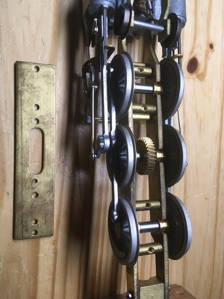
When I built this All Nation model back in 1970, I had the same problem.  The drive bearings have  an external groove  which allows them to fit into the frame slot.  Two had a snug fit, so I made sure they were both on the same axle. I then filed both sides of the axle slot in the frame slightly, until the bearings were a slip-in fit.

When putting on the retainer plate, I found that it touched the rims of all four driver bearings but did not touch the frame by a few thousanths of an inch.  So I filed the rims of each bearing until they matched the frame's bottom edge. Not much had to be removed, but it allowed the retainer plate to firmly fit on the frame with no binding of the drivers.  I did not want to file the axle bearing  slots deeper, as that would lower the locomotive closer to the rails and possible cause the pilot to touch on uneven track or beginning to climb a grade.

Fitting the worm to properly mesh with the main driver's gear required some fussy fitting of shims under the heavy brass mount to get it just right.   A half century later, it still runs great!  I sold it in 2018. Here it is at its new home.BO1447b

S. Islander

Attachments

Images (1)
  • BO1447b: All Nation kit No. 5, built 1970. Re-built as a B&O A-3 in 1988. Constant / directional headlight, on-board synchronized sound unit.
Last edited by S. Islander

Two things that occur to me.   First in the photo of the mech with bottom plate off, it looks to me that there are flat spots on some of the bearings.    Maybe this is an optical (obstacle) illusion?

The second thing is it looks like the side  rods are already attached to the drivers.    The bind may be in the rods not the bearings.     I have a friend who has one of these and I asked him about it.   He said his base plate does not fit tight to the frame either, but his drivers turn freely.    He did not think tightening the base plate could deform the bearings easily.    So my suggestion is to remove the side rods and try installing the drivers and see if they turn freely.    then add side rods one at a time and see which one binds, if it is a rod bind. 

The other idea mentioned above is that the bearings do not slide all the way up into the frame because the flange  way on the bearings is too narrow.   That may be something to look at also.

I have never built one these models.  However looking at your pictures and instructions sheet, I am wondering if the bearings are backwards.  It looks like in your top view picture the part of the bearing outside the frame is thinner and not as high.  The instructions show a large diameter on the outside of frame.   I am an expert, but from the pictures the part of bearing outside the frame looks smaller.   Good luck. 

Thanks for all the help. Good to hear I'm not the only one who has had a similar issue to this, and that filing the bearings fixed it - going to hold off on filing them until I'm sure that's what I want to do.

Since the wheels were binding before I installed the rods, I don't think the rods are an issue. Plus, it all rolls very smoothly with the plate removed.

Looking at the bearings, both ends look like they're the same diameter, and I'm confident that there are no flat spots on any of them.

Thanks for the input, sounds like filing them might be my best bet. I'll probably wait for another day or so before I go ahead with it in case someone comes up with a better solution.

In the mean time, does anyone have instructions for the boiler and tender? I only have the instructions for the mechanism.

I'm also missing three parts so far - the two "piston rod bushings", part 1382, and one of the screws that attach the eccentric rod to the eccentric (I've currently got a different screw in place of it, but having the correct screw would be very nice). If anyone has a parts locomotive, I would really appreciate buying those parts off you.

Add Reply

Post

OGR Publishing, Inc., 1310 Eastside Centre Ct, Suite 6, Mountain Home, AR 72653
800-980-OGRR (6477)
www.ogaugerr.com

×
×
×
×
Link copied to your clipboard.
×
×