


John, any progress on the layout? Track? It's been a while since you posted.
Yep, been a while since I've been able to work on it. Lots of other things seem to be getting in the way.
Time marches on Gramps!![]()
Don't I know it. ![]()
By way of the forum, I talked to Tom this week. I saw that he built model railroad benchwork, so started a conversation about benchwork. He liked the product I had chosen and I mentioned what a fantastic job GRJ had done with Mianne. LOL, if you are following this thread.
Well, it is in my house Keith. ![]() Tom was clearly the architect of great look to the benchwork. My contribution was putting the base together and being an eager assistant, learned a lot of new woodworking skills during this build.
Tom was clearly the architect of great look to the benchwork. My contribution was putting the base together and being an eager assistant, learned a lot of new woodworking skills during this build. ![]()
Tom has shown some of his work and ideas here on the Forum of layouts he built from scratch. I think he really went far beyond on your’s, John, by showing how to make an existing rectangular base table better. I’m sure it was a great experience watching, assisting, and learning from Tom!
It was very illuminating Mark, Tom's a real artist with wood. ![]()
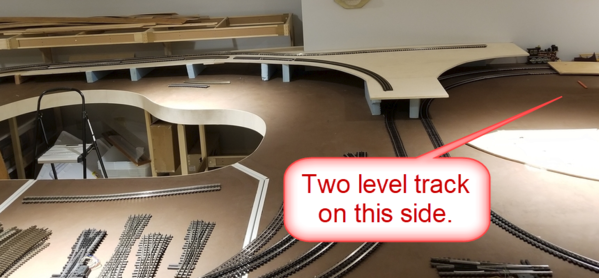
It's been quite a while since I had an update, finally started working on the track. Working on the table level track, finding out that the plan on paper doesn't always work exactly the same way when you have physical track. ![]()


Attachments
Images (3)
@gunrunnerjohn posted:...finding out that the plan on paper doesn't always work exactly the same way when you have physical track.

What? Say it ain't so haha what issues did you run into?
I've relied heavily on software. I hope I don't run into TOO many problems.
John, Now you know why there are 2 S turns in my layout to get the dang thing to fit without major surgery.
I’m glad you are getting some time at it, John!!
@gunrunnerjohn posted:finding out that the plan on paper doesn't always work exactly the same way when you have physical track.
Me too. ![]()
Good to see you are finally getting started on laying track. Did you have to put the double slip switch right on the edge of the lift bridge? Seems like asking for trouble/more work. Or is that the part of the plan that didn’t quite work out?
@gunrunnerjohn posted:
Looks like a giant guitar. ![]()
Great use of the double slip switches John. They will provide immediate access of your yard to which ever right a way you choose. Without them, the service they perform would take quite a few additional turnouts, push back into the grade and require a much longer piece of real estate. Very efficient design, looking great!
Well this should be fun to vicariously enjoy if your epic table build is any indication. Your table is the lamborghini of train tables, so the actual layout should be something special.
How did I miss 23 pages of this thread? Great looking start. Will enjoy watching this one progress.
I like your precise carpentry John. Patient and thoughtful planning pays off for you.
Really looking terrific John, you are going to have a blast running trains on it.
@Will posted:Well this should be fun to vicariously enjoy if your epic table build is any indication. Your table is the lamborghini of train tables, so the actual layout should be something special.
I can't claim credit for the excellent carpentry, I was the apprentice on that job! Tom T. did the heavy lifting, he's something else when it comes to that stuff! I wouldn't have anything like this is it weren't for Tom's excellent skills and guidance. I can do basic carpentry, but I didn't have the knowledge or experience to create something like this ended up. I did learn a lot during the build, and I feel I could do a reasonable facsimile of the build having seen the techniques and done a bunch of the work.
@Lehigh74 posted:Good to see you are finally getting started on laying track. Did you have to put the double slip switch right on the edge of the lift bridge? Seems like asking for trouble/more work. Or is that the part of the plan that didn’t quite work out?
Actually, the two DSS are key to allowing me access to all three loops as well as full access to the yard. I originally had a sea of switches trying to do the same thing, that was one of the realizations I came to after actually setting the switches onto the layout and seeing that reality bites. I had one DSS in the design and switches, I finally realized that another DSS would solve a bunch of the problems that I was addressing poorly with three switches!
@BillYo414 posted:What? Say it ain't so haha what issues did you run into?
I've relied heavily on software. I hope I don't run into TOO many problems.
Things like I used a 101 switch off of the double-slip switch, found out that the 201 switch is what matches the angle of the DSS. Fortunately, I happened to have one of those I could swap out from another place on the plan, so I was able to resolve that easier than many of the issues. I have a bunch of #6 switches that I can't use, turns out they're REALLY for big layouts! I thought it would be nice to have the gradual angle when going between loops, but those suckers are way longer than I could fit in. They seemed to fit on paper, but they sure didn't fit when I got to actually using them. Several other places I had a switch that when I actually got to the actual track it really didn't work out well. One of the issues with designing with Flex track is it's very easy to create almost anything on paper that looks good, but when you try to duplicate it for real, you realize that things don't actually work the way you like.
I'm also seeing stuff that would be really neat to do now that I have actually started laying track down on the table, so the plan is undergoing considerable modification.
I'm from the sectional track camp for my previous builds, and this is the biggest thing I've attempted. It's also my first time using flex track as well. Lessons are coming hard and fast, but I will persevere! ![]()
This is the current plan, but it's undergoing some minor mods as we speak. I have yet to add some extra industry sidings that will show up. If I could figure out how to represent my interior cutout in AnyRail, it would be shown. ![]() The main loop is still what I originally envisioned, a two-level folded dog-bone, total track length around 140 feet. I've added a couple of extra loops on the right, one on each level. I envision them being used for either continuous running when guests are here (if we ever exit lockdown!) and I can't pay attention to what's happening, or simply a nice spot to park a train or two. There is a table level spur on the extreme right that will be my workshop entry spur for launching stuff from the bench.
The main loop is still what I originally envisioned, a two-level folded dog-bone, total track length around 140 feet. I've added a couple of extra loops on the right, one on each level. I envision them being used for either continuous running when guests are here (if we ever exit lockdown!) and I can't pay attention to what's happening, or simply a nice spot to park a train or two. There is a table level spur on the extreme right that will be my workshop entry spur for launching stuff from the bench.

Attachments
Images (1)

Well you're making me nervous. I have also used Anyrail and I have also used #6 switches haha
@gunrunnerjohn posted:
This is the current plan, but it's undergoing some minor mods as we speak. I have yet to add some extra industry sidings that will show up. If I could figure out how to represent my interior cutout in AnyRail, it would be shown.
The main loop is still what I originally envisioned, a two-level folded dog-bone, total track length around 140 feet. I've added a couple of extra loops on the right, one on each level. I envision them being used for either continuous running when guests are here (if we ever exit lockdown!) and I can't pay attention to what's happening, or simply a nice spot to park a train or two. There is a table level spur on the extreme right that will be my workshop entry spur for launching stuff from the bench.
John I love it! Especially the whole "Zoo Junction" thing you have going on center right! Philly / Pennsy people know what I'm talking about ![]() Would you please be kind enough to post your current AnyRail file? I would like to explore the right side in more detail. What a fun and exciting time this must be for you!
Would you please be kind enough to post your current AnyRail file? I would like to explore the right side in more detail. What a fun and exciting time this must be for you!
Make sure you turn the column into a giant smokestack.
@BillYo414 posted:Well you're making me nervous. I have also used Anyrail and I have also used #6 switches haha
They didn't look that big on the plan, but they sure grew when I got the boxes! ![]() They're over 19" long, for some reason that didn't seem that large when I plopped them onto my initial plan.
They're over 19" long, for some reason that didn't seem that large when I plopped them onto my initial plan. ![]()
@Ted S posted:John I love it! Especially the whole "Zoo Junction" thing you have going on center right! Philly / Pennsy people know what I'm talking about
Would you please be kind enough to post your current AnyRail file? I would like to explore the right side in more detail. What a fun and exciting time this must be for you!
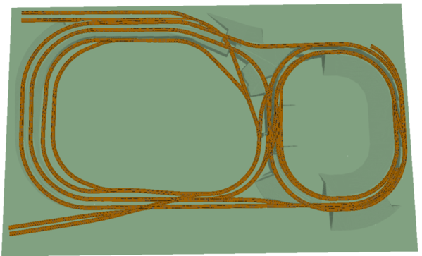
Looking to see the 3-ring circus? ![]() Here's my latest plan, but I'm already ripping that apart to make it closer to what we actually have on the table now that I've discovered some flaws in the layout.
Here's my latest plan, but I'm already ripping that apart to make it closer to what we actually have on the table now that I've discovered some flaws in the layout. ![]() The plan below reflects what is in the 3D view, things are changing as we speak.
The plan below reflects what is in the 3D view, things are changing as we speak.
Attachments
Files (1)
Ex-PRR Zoo interlocking, Philadelphia PA
When I was 8 my parents took me to the Zoo. I spent most of the time on the monrail platform watching Amtrak and PC GG-1s navigate this maze of trackage. It's multi-level, just like GRJ's!
I’m concerned that having the double slip switch right on the edge of the lift bridge, you will have some very short pieces of track if you cut the track at the edge of the lift bridge. I suppose you could have the track that is on the lift portion hang over a bit long to avoid those short pieces.
That's exactly what is happening, they're going to hang over half an inch. I don't want half inch pieces of track. ![]()
John, it is hard to see what is going on in the center there. I can see there are two levels, but I am having trouble pulling them apart. Does your software let you color code the different levels? Or if you send me a plan of each level ( top view, .jpeg or .png- could be screen save ) I can bring them into Photoshop and superimpose them and add color for each level.
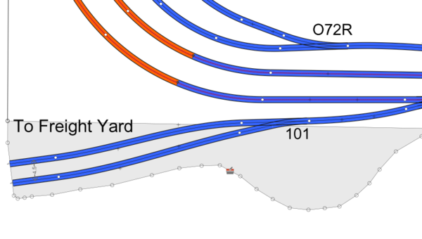
Here's the table level track and the elevated level track. This is close to what it'll be, but some things are getting moved around slightly, I'm in the midst of cleaning up the plan... again. I haven't shown any sidings yet, still deciding exactly where they'll be.


Attachments
Images (2)


GRJ
Glad to see your are designing and building a layout in addition to your role as a regular contributor to this forum. Now you can do your "day job" 8 to 5, contribute to the OGR Forum 6 to 10, and immerse yourself in layout plans from 10 to midnight. That schedule will keep you off the streets and safe from COVID-19!
Carry on, valiantly ...
Mike Mottler LCCA 12394
mottlermike10@gmail.com
You must have been peeking in my window last night, it was right around midnight when I closed up shop! ![]()
Glad to see you working on your lay-out again, keep up the good work.
Now if Alex M could get back to working on his instead of all those repairs!
Redball 342
Spent a few hours, cutting lumber for the elevated sections. Got the ramps cut, just need to cut the loop for the elevated track on the other end. Obviously, the blocks were just for sizing and checking elevation, I have to work on the permanent supports. The bit piece on the end gets a center section cutout, but I'm going to finalize the exact location of the track there before that happens. Have some trimming to do on one of the other pieces, but it's nice to make some progress. ![]()


Attachments
Images (4)
Really like the way you recessed the 1/2" multiply into a cut out of the 1/2" homosote. Nice blend job. Great transition. Real clean work forming the wye at the top of the ramp also.
Thanks tom, I don't know where I could have gotten the idea of recessing the plywood into the Homasote! ![]()
![]()
It's slowly taking shape, but I'm getting a little more excited. Miles to go before trains run, but every journey starts with a single step. ![]()
John,
Looking very nice, and making progress.
Alex
Thanks Alex, I'm looking forward to the end result. ![]()
Looks good John. I assume you still need to lay cork roadbed?
Bob
I actually have foam roadbed, I will be putting that down when it's time. However, the ramps are only a "trial fit", they're not actually going to be supported with blue foam, that was just getting them all cut and fitted. Still to go is cutting the elevated section on the right and having all of it fit together. Once everything is cut, I can start laying the track permanently under the elevated sections and then get them nailed down.
Attachments
Images (1)

Looking great John. One thing I wouldn't have the patience for is testing with levels. I would be going bonkers out of my mind when the engine stops and all I do is not having any effect on anything. I did that with HO but that was one level and that was a pain. Took forever to find the disconnect.
I'm not anticipating any issue with locomotives stopping because they on the second level, not sure why that would be an issue. I do plan on wiring all of it properly, of course. ![]()
Gunrunner John, your table work is awesome, just wondering if you plan to use cork roadbed, or some other type of roadbed under the track? Also, are you using Gargraves or Atlas O track? Watching this neat layout unfold will be a lot of fun as I’m sure with your electrical knowledge it will be state of the art. It’s an exciting time in our hobby with so many neat train items available from our manufacturers. Keep the pictures coming. Happy Railroading.
I'm trying out foam roadbed for the first time, it's the same thickness as the cork. I'm using Gargraves track and Ross switches. The switches and any O72 sectional track is Ross, the larger curves are Gargraves flex.
@gunrunnerjohn posted:I'm trying out foam roadbed for the first time, it's the same thickness as the cork. I'm using Gargraves track and Ross switches. The switches and any O72 sectional track is Ross, the larger curves are Gargraves flex.
What kind of foam are you using?? What's your source?? TIA..
@gunrunnerjohn posted:I'm not anticipating any issue with locomotives topping because they on the second level, not sure why that would be an issue. I do plan on wiring all of it properly, of course.
The chance of any mishap occurring is directly related to the risk of damage to the equipment.
Well, wide curves, wide right-of-way, and slow speeds would seem to minimize the risk of damage. We'll see, but that's not my chief worry.
It is looking great, John!! ![]()
![]() What does Tom mean by recessing the plywood into the Homasote? Now that my benchwork and roadbed is about done, I need to learn what I did wrong. Tom also showed me where I could have purchased really neat benchwork on another current OGR topic!!
What does Tom mean by recessing the plywood into the Homasote? Now that my benchwork and roadbed is about done, I need to learn what I did wrong. Tom also showed me where I could have purchased really neat benchwork on another current OGR topic!! ![]()
R We runnin' yet????? ![]()
@Mark Boyce posted:What does Tom mean by recessing the plywood into the Homasote?
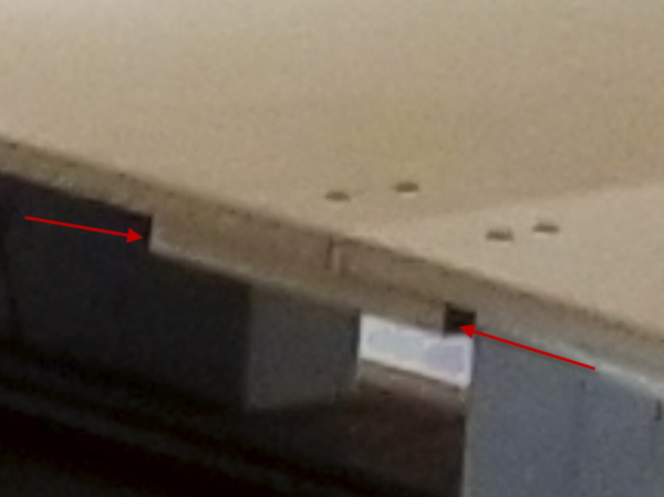
Mark, in order to start at table level with the elevated track, you have to taper into the Homasote, see below. The 1/2" Homasote is cut out and the 1/2" plywood for the elevated ramp starts at table level there.
As you can see, the indicated spot actually has the ramp plywood even with the Homasote and it gradually ramps up. I have a couple of feet of gradual ramp easement to minimize issues transitioning into the grade.

Attachments
Images (1)

@Woodson posted:What kind of foam are you using?? What's your source?? TIA..
I bought it from a guy on eBay, since I'm not allowed to post ebay links here, drop me an email and I'll give you the poop on it.
@gunrunnerjohn posted:Mark, in order to start at table level with the elevated track, you have to taper into the Homasote, see below. The 1/2" Homasote is cut out and the 1/2" plywood for the elevated ramp starts at table level there.
As you can see, the indicated spot actually has the ramp plywood even with the Homasote and it gradually ramps up. I have a couple of feet of gradual ramp easement to minimize issues transitioning into the grade.
Thank you, John. I can see where the lighter layer is tapered down to the darker layer, and it will make a great vertical easement into your grade. So are you grinding away plywood, Homasote, or both to get the taper?
Just cut up the Homasote layer and screwed the ramp plywood right to the wood under the Homasote. The ramps won't have a Homasote layer, just the foam roadbed.
Thank you, John! That makes sense to me now!!
Moving along nicely John!
Great work John. Interesting design and levels. I enjoy watching the progress.
If you wish to use Homasote on the elevated portion:
Once you have established the smooth vertical curve transition into the incline then you can terminate that piece of plywood and continue with incline plywood by lowering the incline plywood 1/2" and back it up 8" +/- and attach the top of the elevated plywood to the bottom of the transition piece. This gives you a 1/2" step to continue with Homasote for the remainder of the elevated portion.
For purposes of this paragraph let's just imagine the dual track subroadbed is 9" wide. When you have already cut your subroadbed material and it is on a curve where backing it up would not be work well then simply fabricate a matching curved 9" X 16" gusset attaching it 8" (half way) under the severed incline, add a 9" X 8" piece of curved plywood on top of the exposed portion of scabbed gusset as a extension of the established incline. Now that 9" X 8" add-on-piece becomes the sandwich interface for the bottom of the vertical curve transition piece. With that done you have a 1/2" step down and to accommodate the 1/2" Homasote and can now continue on up the hill with Homasote.
Once you work with Homasote it is hard to go back to laying right a way on plywood decking.
Continuing: if dropping the rest of the 1/2" plywood ramp happens to mess with your calculated clearance for the lower tracks which you are going to pass over, no problem. Just use the step method again. Stop the plywood 4" back from the C/L of the lower track, stop the Homasote 12" back from the C/L of the lower track, and instead of using Homasote use the 1/2" plywood as a replacement for just over the lower track. This will recapture the clearance you originally desired. Now once past the lower track reverse the step to return to a Homasote working surface.
Over pass Homasote substitution example:
Because of the shallow angle of the overpass the 1/2" Homasote replacement is quite long. The brown paint is where the Homasote stops. The plywood is the same stiff 1/2" Birch multiply we used on GRJ's main decking.

This view shows how long the top plywood gusset had to run. The spiral easement template is to draw a centerline for the track.

The intrusive block corner is now embraced with a light weight removable mountain so as to be able to easily service the turnout
Attachments
Images (2)
Holy Cow Tom, that looks way beyond my capabilities. ![]()
In any case, I've decided not to add Homasote to the incline. My grades are at around 2.7% now on the ramp, I don't want to push that any more. The top level is at 7", that gives me just enough clearance for the tallest car we could find, the MTH Autorack at around 5 1/4".
It's just a lot of words. I would be glad to stop by and cut in the 1/2" step for you. Should take less than an hour. Nothing in my previous post will affect the rate of the grade percentage.
If you let me loose there I might just back up the start of the vertical curve transition to the slip switch and further reduce the grade percentage ![]() .
.
John, I just rolled back up the screen and noted what looks like the second track for the yard is coming off the start of the outside curve. Is this an added on stub siding or the second yard track?
I believe my bump out allowed for both yard entrance tracks to come off of the double slip switch which would allow for a longer grade. Please refresh this old man's memory.
Tom, you're actually correct. Somehow that got lost in the shuffle, I liked it better the way we had it before. It's back, and I even save a switch, I already have the 101 in hand. ![]()
I added the table extension as near as I can come with the track planning program. ![]()
Attachments
Images (1)

So, the old man (your's truly) is not totally out to lunch, yet!! Any thoughts as to backing up the start of the incline?
If you come off the slip switch with an immediate right hand switch instead of the left hand you will eliminate the "S" curve and extend the dual tracks.
@Tom Tee posted:It's just a lot of words. I would be glad to stop by and cut in the 1/2" step for you. Should take less than an hour. Nothing in my previous post will affect the rate of the grade percentage.
If you let me loose there I might just back up the start of the vertical curve transition to the slip switch and further reduce the grade percentage
.
Well, it was a lot of words! ![]() With that switch removed, I could start the grade earlier, that's not a bad plan.
With that switch removed, I could start the grade earlier, that's not a bad plan.
@Tom Tee posted:So, the old man (your's truly) is not totally out to lunch, yet!! Any thoughts as to backing up the start of the incline?
If you come off the slip switch with an immediate right hand switch instead of the left hand you will eliminate the "S" curve and extend the dual tracks.
I fooled around with that, but the angle the switch comes off still gives me an S-curve as I have to avoid the edge of the table anyway. My table representation is not "quite" real, I may have to fine tune it.
That sounds slick, Tom!! ![]() You will have all of us tearing out our roadbed and starting from scratch before John has his layout up and running!!
You will have all of us tearing out our roadbed and starting from scratch before John has his layout up and running!! ![]()
John, How about a wide radius RH Ross curved switch butted up against the slip switch?
You just need to see how many degrees of curvature their widest curved switch has compared to how many degrees of curvature is needed coming off the slip switch then determine how many degrees of curvature you can remove from the curved switch if needed. Ross switches lend themselves readily to serious surgery
Mark, that is just my way of developing job security. ![]()
@Tom Tee posted:John, How about a wide radius RH Ross curved switch butted up against the slip switch?
You just need to see how many degrees of curvature their widest curved switch has compared to how many degrees of curvature is needed coming off the slip switch then determine how many degrees of curvature you can remove from the curved switch if needed. Ross switches lend themselves readily to serious surgery
Mark, that is just my way of developing job security.
Excellent point, Tom! ![]()
In staring at the angles depicted above I was nudged into another direction. As one who builds primarily with standard sized turnouts sometimes I come across a situation where a custom turnout can ease the track alignment.
Working off the angles shown above lead me to consider the idea of a shallow wye or a custom turnout. I have been using custom turnouts on an infrequent basis for many years. Examples follow:
This juncture of the track centerline approaching a TT proved awkward with both a numbered switch and a normal curved turnout. So, in three rail parlance, a 0180"/0264" made the flow nice and smooth.

So also in another situation, when a busy module was added to an existing RR nothing off the shelf seemed to work. So an usual critter from a custom fabricator made it work.

I have seen examples of Hikel layout Service doing similar work in 3 rail using Ross frogs. Just a thought to tuck in your file.
Attachments
Images (2)
@Tom Tee posted:John, How about a wide radius RH Ross curved switch butted up against the slip switch?
You just need to see how many degrees of curvature their widest curved switch has compared to how many degrees of curvature is needed coming off the slip switch then determine how many degrees of curvature you can remove from the curved switch if needed. Ross switches lend themselves readily to serious surgery
Mark, that is just my way of developing job security.
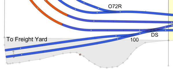
The switch is the #100 11 degree switch. I swapped the #101 shown previously for the #100, it looks like a better fit. As for changing the angle of the Ross switch, I don't think I want to try that, I don't see any easy way to accomplish that. I do see that I could easily destroy a perfectly good new switch in the attempt. ![]()
Attachments
Images (1)

I really like the refreshed configuration. Nice
I think that switch works better. I was just trying to save a hundred bucks and use one I already had! ![]()
You also enough available length to use one of those long #6 switches.
I thought about that tom, but they're all left hand switches. If I had a right hand one it would have worked out well.
John, That last diagram looks pretty good!
Chris
LVHR
Probably as good as it's going to get Chris, I think I may extend my ramp a little now that I got rid of the switch on the curve. I want that grade to be as gradual as possible. Right now it computes to 2.4%, but the program is not allowing for the easements at the ends, so I think it's going to be at least 2.5%-2.6% when the smoke settles.
Cutting more wood for the elevated sections. Working on the missing sections, too bad I don't have 10x10 plywood, it would make this easier. ![]()

Attachments
Images (1)
Coming along nicely John. Looks great!!!!
All the major pieces of wood are cut and fitted, still need some cleanup on the edges, but I'm hearing the trains coming 'round the bend! ![]()


Attachments
Images (2)
John forgive me if you've already answered this. I know the foam blocks are just for test fit purposes, what are you going to use for the final support of the elevated sections?
We've been discussing that. My initial idea was some faux concrete supports, but that may change. I tried to leave plenty of "meat" on the edges so any reasonable solution would work I will probably also trim the splice blocks that join the sections back from the edge to allow a support right at that location. All of this has to come off once it's all cut and fitted to lay the table level track, so now it's only temporarily screwed together.
Attachments
Images (1)

It's really starting to look like a layout....not a dream.
Keep it up and you will be running trains by Christmas John.
Bob
I better have them running by then, my wife is giving me grief about trains for Christmas! ![]() I hope that the first run will be comfortably before then, but a pacing item may be the Ross switches I need to finish.
I hope that the first run will be comfortably before then, but a pacing item may be the Ross switches I need to finish.
@gunrunnerjohn posted:All the major pieces of wood are cut and fitted, still need some cleanup on the edges, but I'm hearing the trains coming 'round the bend!
John,
How did you get the radius cuts to well looks really clean?
Joe Gozzo
You make cardboard templates first and then trace them. I've smoothed the edges with a belt sander, and I still have some work to do there. When I disassemble it for the table level track installation, I'll do a bit more work on it. It's easy to make them look smooth in a picture, they're not that perfect. ![]()
A quick "flight" over the first loop of track actually in place. ![]() Ignore the loud scraping noise, that's me moving the table so I could walk by.
Ignore the loud scraping noise, that's me moving the table so I could walk by. ![]()
Progress John, good progress!
I'm doing a little "fine tuning" at my main junction spot on the lift-bridge, I have two tracks a little too close for comfort.
Congrats on "first track laid". Has "first blood been spilt" yet or are you an injury free railroad? 😄
-Greg
First blood was spilled before the first rail was down! ![]()
Congratulations John.
Who is that indeed. Nice little video John. Looks great. Keep up the great work.
It was a spur of the moment video, we finished up and I just whipped the phone out. ![]() I was checking an my plan has 310 feet of track already and I haven't added my 8-track yard! It sure adds up in a hurry! With the removal of the second level shelf I was able to sneak a couple of yard tracks in the back that will be useful.
I was checking an my plan has 310 feet of track already and I haven't added my 8-track yard! It sure adds up in a hurry! With the removal of the second level shelf I was able to sneak a couple of yard tracks in the back that will be useful. ![]()
Attachments
Images (1)

Looking great. Can't wait for more updates.
John will you consider using a drone for your next video please
John I noticed a black line on the table outside of the track radius. Is that the location of another track, approximate clearance required for scenery and structures, a future cut?
@trainbob posted:John will you consider using a drone for your next video please
Will you consider sending me a suitable drone?
@coach joe posted:John I noticed a black line on the table outside of the track radius. Is that the location of another track, approximate clearance required for scenery and structures, a future cut?
That's the overhang of the upper deck, we just put the line to know where it is and to leave space for the supports. After cutting and fitting all the upper deck, I removed it to allow for finishing the lower level track.
That is looking good, John.
It would be really nice if it were looking like trains running, but at least we're heading in the right direction. ![]()
JOHN: When you post video and similar "news," please edit the thread title to say "Update (insert date) ...." or something equivalent to alert folks that you've posted new info.
Add Reply
Sign In To Reply
