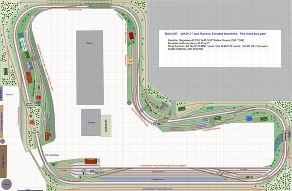
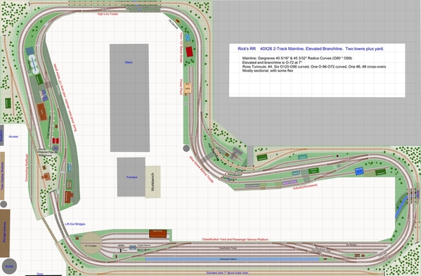
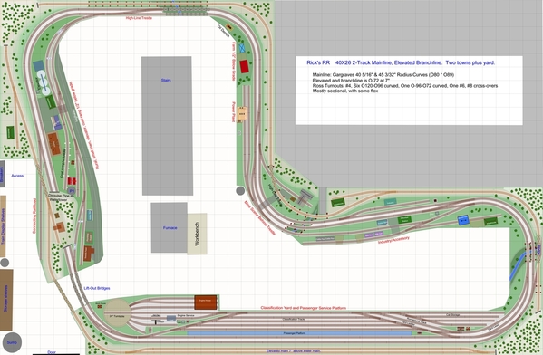
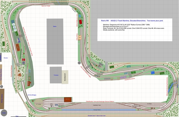
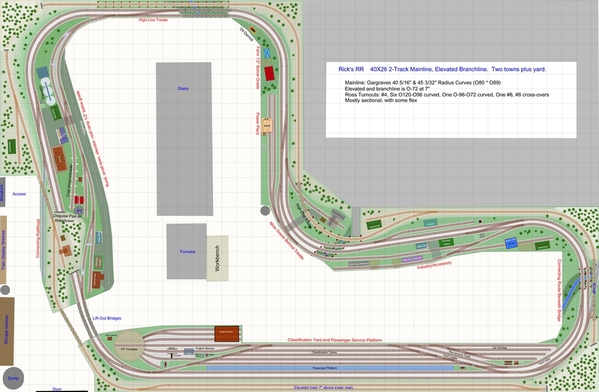
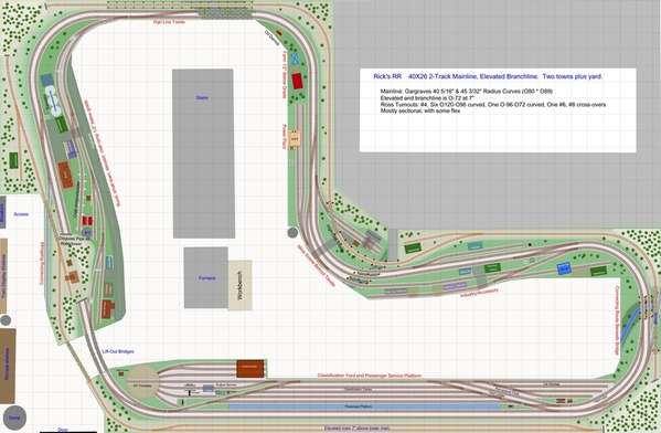
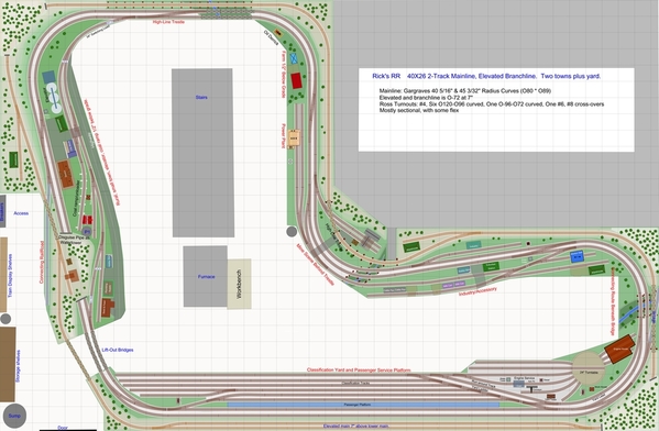
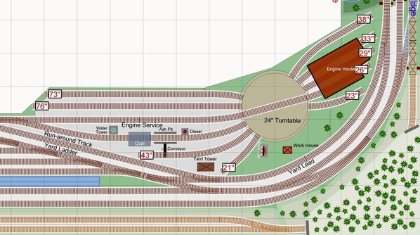
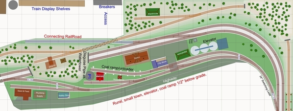
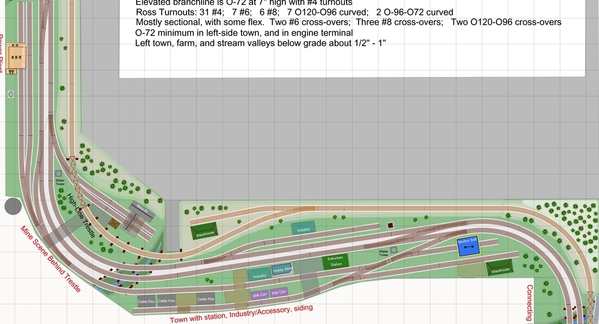
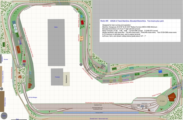
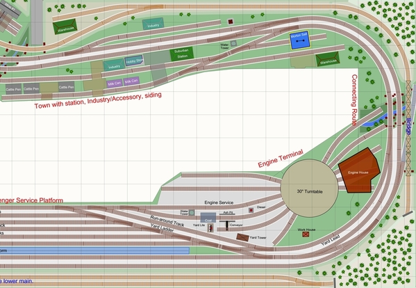
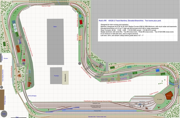
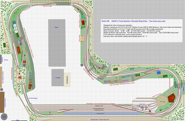
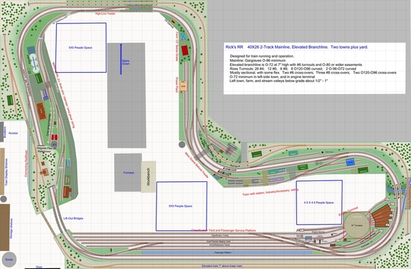
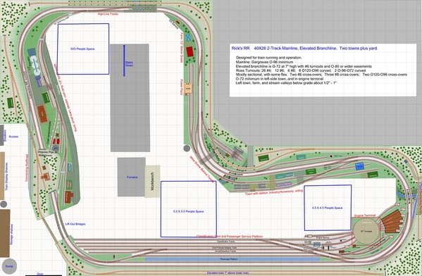
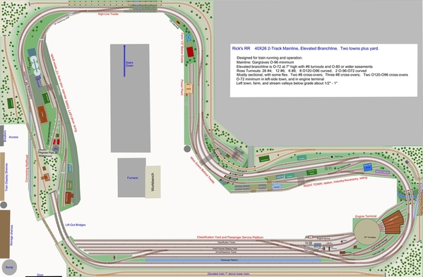
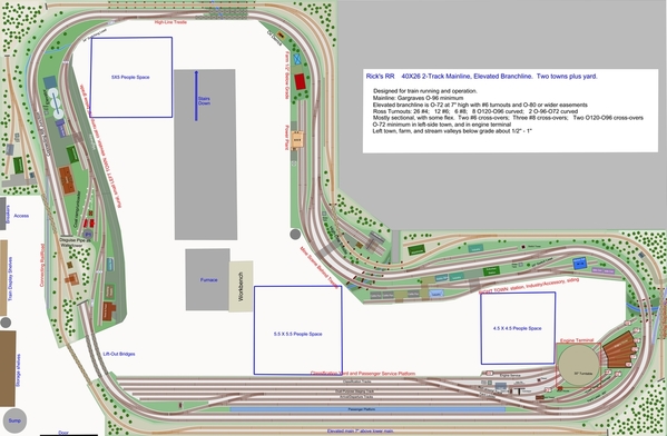
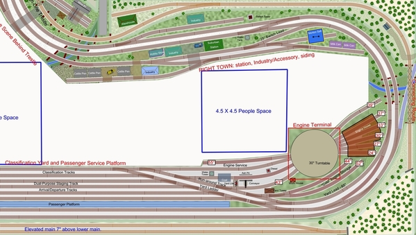
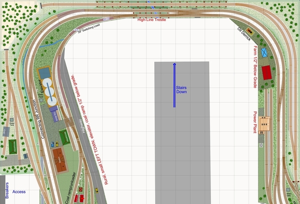
This layout plan fits Rick's 26.5' X 40' basement layout space.   Rick wanted broad curves to run passenger trains, a two-track mainline with Right-Hand running, and elevated "High-Line" third route, a small town with grain elevator and coal unloading trestle, and a yard with classification tracks, a passenger platform, turntable, run-around track, yard-lead, and car storage tracks.   The mainline is a minimum diameter of O-80 using Gargraves sectional curves (but many curves wider than that) mixed with some flex sections, and a minimum of Ross #4 turnouts.   There are over five scales miles of track!   Rick wanted to use Gargraves track and Ross switches, which turned-out to be a great choice for the layout planning!

Before deciding on this track plan arrangement, we looked at and considered many alternatives, including return-loops, and grades to connect the High-Line and main level.   The overall shape of the basement and the configuration of the stairs, furnace, pipes, exterior door, and access to the breaker-box constrained and guided the track plan, which went through multiple configurations.   Rick wanted to do right-hand running and trailing-point switching for the most part.   

Each of the two towns have sidings or a run-around track.   The larger town industries in the upper left are accessed by a separate route where a train leaves the main line and descends at 2% down 1/2" in elevation; giving the sense of trains leaving the main line to wind through the town while the main lines pass the station at the edge of town, with a highway running through town in the immediate foreground.   In this town, there is a large passenger station on the mainline, while in the smaller town at the right, a smaller station sits between the mains and a siding.

Ross turnouts were used exclusively, and are offered with a wide variety of turnout sizes and configurations.   This plan makes good use of Ross O-120/O-96 curved turnouts, which allow smooth and broad curves and cross-overs into and out of the yard.  There are also three #8 single cross-overs so trains can switch mains and allow faster passenger trains to work past slower freight trains.   With the #8s and the O-120/O-96 there are a total of five cross-overs between the mains - a lot of flexibility and fun train operation.

Rick has a group of railroad friends who will help in the construction of the layout, and provided helpful input and suggestions which were incorporated in the design.  We hope you enjoy Rick's layout plan!

Ricks-O_GG-Ross_V6a-LabeledTrackPlan

Attachments

Images (1)
  • Ricks-O_GG-Ross_V6a-LabeledTrackPlan
Last edited by Ken-Oscale
Original Post

Replies sorted oldest to newest

Where does it go and what does it do?    I see no staging or interchange with out railroads.    What is Rick's desire for operation?    Or does he just plan to run trains around?     Fine to do a display layout for just running trains, but there is a lot of track there for that kind of layout in my opinion.

The gent's name is Rick Arestad, a forum member.

PRRJIM:  As to the purpose of the RR,  to have fun and enjoy the hobby.   Not every model RR needs to be a reduced/compressed version of a prototype RR subdivision, this RR is not modeled on any prototype.   Folks differ in their views about what a train layout is and how prototypical these toys need to be in order to enjoy them.   This sort of topic has been discussed on the forum before, with differing opinions.   Perhaps it boils down to the level of abstraction (and imagination) each individual prefers for their layout.

  • yes, one purpose is to run trains.
  • But you can also see that there are two stations and a station platform: passenger trains can run from station to station, and make additional loops in between.  Houses or apartments for each pretend passenger are not needed, nor are cars and taxis and highways to get the pretend passengers from station to home to work required, nor jobs for each of them to work in the city or suburbs.   
  • There are also eight industry sidings on the main lines.   There are four involving coal - a coal loader and unloader, and a power plant, and a mine, so a "prototypical" movement of coal from the mine to the yard, then out to the power plant with empties back could be done. Diverting some coal to the coal unloader for fun.   
  • Rick will be able to make up and run trains and service industries on the spurs, moving cars from the yard to the spurs, and then in another run, pull the cars back to the yard.  Abstractly "modeling" the function of real railroads.
  • It would be a small feat of imagination to pair-up industries in the two towns, so one can pull a car from one industry, drop it in the yard, then make up a train to take them to the other town.  Lots of possibilities for Rick to explore.
  • There are other sidings for animated accessories - milk unloader and cattle car pen.   

Sure, one could claim (for instance) that you must not have a cattle car and pen which loads and unloads the same cattle into the pen because its not realistic or prototypical, but its a fun accessory.  No abstract representation of a ranch, or meat packing plant, or meat market, or dining customers are needed in order to enjoy it.

A spur or siding could certainly be added to abstractly model a connecting railroad, I have done that on other plans.   But that would still be just an imagination idea, whether the spur is there or not.   There would not actually be a connected railroad even if the connection spur exists, it would have to be modeled in the imagination, but would really just be a place to store some cars, and then pull them back to the yard again later.    For this plan, perhaps a connection could be added to an imaginary connecting RR coming off the right side of the yard and running to the right beneath the "high line" could be added, might be fun to do.

Anyway, this is the kind of 3-rail O-gauge RR Rick wanted, and I think it is perfectly fine, I would love to have this in my basement! 

As a more practical consideration, Rick wanted relatively broad curves and turnouts, looking forward to running some longish passenger trains.   I thought about squeezing a second yard into the space (in order to run trains between division points), but decided it would mean deleting a town and tightening the curves for a more compressed layout.   And the runs between yards would be pretty small  Always a trade-off.   We initially talked about a shelf above for a longer run, and we discussed return loops so one could have a point-to-point that allows trains to turn for continuous running.

-Ken

Last edited by Ken-Oscale

You make a lot sense including only one  yard.   John Armstrong emphasized in his many books, that generally (there are always exceptions),  you should include only one of each element, and do it well, rather than including 2 or more and making each one too compressed or reduced to be interesting.

I don't fault your approach for a display layout.   If that is what is wanted, that is fine and will be enjoyable.    I was just asking.   There seemed to be quite a few elements pointing both directions in the plan - it was not quite apples, and then not quite oranges as they say.  

My interest is more toward operations, so I always look at a plan to see what the trains are going to do.    Generally my concept is a spur or two as interchange tracks, and then a yard, and finally quite a few industries, since I like switching them.     The interchanges can be expanded to include whole trains with locos or just be a string of cars.     The operating plan is to put a train of outbound cars together in the yard, and run to the interchange.   There the outbound cars are exchanged for the inbound ones, and the train returns to the yard.     The cars are then classified by destinations served by the local freights - could be by town, or type industry etc - based on what the operator has envisioned.     Locals are then assembled and go out to the towns and exchange setouts for pickups.    They return the pickups to the yard and the cycle begins again.      This concept can be so small as it is all one train and the yard is an engine house and a passing siding.    Or it could be big enough to include many trains all doing different things.    

I do notice you do not have a yard lead separate from the main, and it looks like to me the single track loop is not connected to the rest of the RR.    A separate lead allows the yard to be worked without interfering with the mainlines.


Jim, thanks for your comments.  The yard lead does connect to the main for convenience, but is not on the main itself.   Using the lead does NOT block the main lines, and this connection allows a train that is heading into the yard to pull in via the yard lead, so as to clear the main line more quickly, not leaving its caboose dangling on the main, and slowing down the following train (likely a fast passenger), while the locomotive works through the ladder and the classification tracks at slow speed.   I thought about extending the lead for more length, but then it would effectively wrap around to the town above the yard - not sure if that is a good idea or not.  And I thought then the lead would need its own bridge over the stream on the right side, so there would be THREE bridges AND a trestle all in the same small footprint, perhaps not a good visual idea.  Extending the lead would be easy to do - what do you think?

The operating plan you describe is one that Rick can be able to implement: making up outbound trains in the yard, running around the road switching industries and returning to the yard.  An interchange operates as one more "industry", where cars are picked-up and dropped off - albeit a bigger industry, and perhaps requiring the cars to be dropped-off to be organized and ordered.   I'll look at adding a connecting spur off the yard on the right side if Rick is interested.   Things are pretty tight there already.

-Ken

I know we all model in different ways( loop running, prototypical operation, etc.) and tend to view a layout from the perspective of how we operate our own trains.  I think diversity is one of the things that makes this hobby so great. That being said, this plan would be perfect for me. Double track main for continuous running and just enough sidings/industries to keep the switching interesting.

There is one thing I would do different with this plan. Since the upper loop is physically separate from the rest of the track and seems to run through a mountainous area I would make it an On30 logging road, and maybe put a mine in the top left corner.

Ultimately this is Rick's layout and he has to build a railroad that makes HIM happy. 

Ken,

Sorry, I missed the crossover from the yard lead to the ladder when looking at the small picture.    When I opened it, I saw that.   I originally thought the lead just went around the yard.   You are right visually and prototypically,   running the lead out across the bridge does not seem to appeal.    I suppose you could move the river if you wanted a longer lead.   I am not sure how long string it can hold.    It looks like you could pull any but the longest track.   

A thought, if you want more yard, make it stub-ended.    I would love to have a double ended yard like that, but with number 6 switches, the 2nd ladder eats up enough space to put 25-30 cars.   

As for the following comment on the engine terminal, it could be moved to the other end of the yard and jutted out into the room to add more tracks, or longer tracks and the "car storage tracks" could be moved to the other end of the yard.

Rather than put the interchange next to the yard, consider putting it on the other side of the room.    You could run a track or 2 off the main and go under the scenery and the upper level loop.    Perhaps instead of the coal mine scene behind the trestle, have the interchange come off near where the road goes up to the trestle and go under the trestle and under the upper level scenery.     Might room enough for 2 whole trains side by side.

Another really far out plan is to come off the main across from the elevator and go under the upper level in onto a shelf in the "acess" area.   A 4 inch shelf would hold one string of cars and an 8 inch wide shelf would hold two.    Additional shelves could be put in above and below and used to store cars not on the layout.    Then they could be "fiddled" on and off the staging tracks.   

Jim

SouthernMike:  I am also a fan of On30, and would strongly consider that guage for the upper level route if this was my layout.   Rick decided on O-gauge for the "High Line".   Either way, this route adds more interest and fun, and opportunity for great scenery and structures. 


The yard lead is 79.5 inches in length, not counting the switches or any use of the ladder.   That seems likely to be sufficient for pretty much all switching moves of cuts of cars.

-Ken

Last edited by Ken-Oscale

I came up with this modification the other day, as a possible change.   Looking at the town at the right, and extending around toward the mine and coal power plant.    The siding through town is extended around the curve toward the power plant.   It extends the siding for a longer train to pull through the this town, and allows Rick to switch the power plant from the siding, thus clearing the mainline, and also allows longer industry/accessory space.   What do you think?

Ricks-O_GG-Ross_V6b

Attachments

Images (1)
  • Ricks-O_GG-Ross_V6b

Here is an option for a connection with another railroad, a branchline, or perhaps an interchange track as we have been discussing.  Its on the left hand side along the access to the breaker-box.   Being on the other side of the mountain adds a feeling of separation and "over there" supporting the idea this goes somewhere else.   Its all visible, so no hidden tracks to hassle with.   And it adds another bridge with the connection running beneath.  [Though it certainly could dive into a tunnel instead, creating a hidden track, with open access to the passageway.]  The diverging turnout is a #6, and the track is just over seven feet long, if used as an interchange track, its a "facing-point" turnout for right-hand running, but is OK if imagined as a branchline or connection.   The "high-line" mine spur was shortened, and some scenery area is lost, for a busier look more dense with track.  

On the right-hand side, I experimented with a connection to another railroad running beneath the bridge of the high-line.   Not sure I like this addition, left a bit rough/unfinished in the picture.   Its a bit hard to see unless you can zoom the picture or download it to view it.  This connection is made with an O-120/O-96 curved turnout on the outer main.

Comments?

Ricks-O_GG-Ross_V6d

Attachments

Images (1)
  • Ricks-O_GG-Ross_V6d
Last edited by Ken-Oscale

Ken,

I'm a fan of operations.  I think that there should be a yard lead on the left side of the classification tracks to allow a switcher to move a string of cars from and to these tracks to the car storage tracks without having to do a lot of running around the string so that it pushes the string into car storage.

I think it would enhance operations if the upper track was connect to the lower tracks so that it could function as a branch line.   You would need to add an interchange track and adjust grades ans elevations.

Jan

Jan, a yard lead on the left-hand side of the yard to allow switching service from both directions would have to cramp the space for the turntable and whiskers, and would need its own lift-out bridge across the access passage.   All of that to avoid a runaround move of a switcher?   If your idea is to have a switcher "posted" to the left side of the layout just for these moves, couldn't a switcher from the engine terminal already on the left-hand side accomplish this?

I am thinking that a switcher on the right side can assemble a cut of cars on the top yard track, and a switcher from the engine service area can push the cars into the car storage tracks.  Seems simple.

As mentioned, I discussed with Rick connecting the upper track to the lower level, but he decided against it.   The grade(s) would take up a lot of real estate.   Here is one version where I played with the idea of inclining the outer main line (at the bottom of the plan) to reach the level of the "High Line" (which was at 6" in this plan), to make a connection.

Ricks-O_GargravesRoss_V2c

Attachments

Images (1)
  • Ricks-O_GargravesRoss_V2c
Last edited by Ken-Oscale

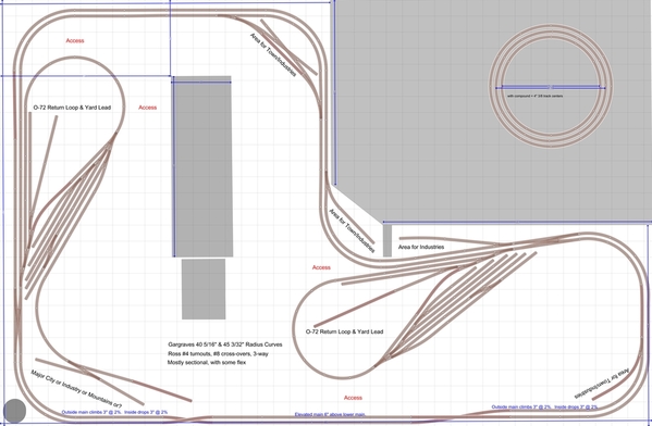
Some of you may find this interesting:  during the early conceptual exploration of possibilities, I sketched-out possible return-loop possibilities in Rick's space.   Rick decided he was not interested in these return-loops, and they certainly do fill the available space and cramp access and movement around the layout.   One can imagine alternate positions for these return loops, but this serves to get a feel of what can be done in the space.   Return loops of large width create access/reach problems - the loop on the lower right is accessable from multiple sides, as is the loop on the left.

Ricks-O_GargravesRoss_V1d

Attachments

Images (1)
  • Ricks-O_GargravesRoss_V1d
Last edited by Ken-Oscale

Going back to the comments about the location of the turntable and engine area, I thought about swapping this with the car storage area earlier in the design.   The space available is actually larger on the left-hand side than the right, so the TT-engine yard is in the bigger area.   

Still, with a swapped locations, the TT-engine area could be made larger by jutting-out into the human space toward the current stream.   This would create an unreachable deep area in the lower-right corner.   Plus humans need a space to congregate without being cramped.

Anyway, these two whiskers can be lengthened for more loco storage.   Is that a good solution to this concern?

Ricks-O_GG-Ross_V6e

One more engine track can be squeezed-in this way (O-96-O72 curved).   I would want to test this idea of having a curved turnout just off the turntable.   Will the sideways forces of a loco on a curve push against the TT causing it to slip its alignment against the whisker track?  - depends on how strongly the TT holds its alignment.   It think this will probably be OK with slow speeds and the deep flanges of our O-gauge locos, but worth testing.

Ricks-O_GG-Ross_V6f

Attachments

Images (2)
  • Ricks-O_GG-Ross_V6e
  • Ricks-O_GG-Ross_V6f
Last edited by Ken-Oscale

I did a bit of scenery detailing around the two connecting route options (so far), and off-colored the track for visibility.   I like the connecting track on the left for the reasons mentioned above.   Trains heading out on the connecting route diverge on the turnout right-hand running.  An arriving train must travel against the normal direction around the layout to the cross-over adjacent to the mine, and there cross-over to the "inside" main for proper direction running.   If Rick wants to replace the single cross-over beneath the top trestle, with a double cross-over, a train could change mains there.  But that is a lot of additional expense for an imagined connecting route junction.   Perhaps better to add a single cross-over past the station for this movement.   I see that the car storage shelves are directly adjacent to this connecting route, and would be an easy place to add or remove cars and locos from the layout.

Still not sure about the one on the right:  the connection runs beneath a long bridge or trestle for the high-line, making for a complex scene here, which could be a cool look.

Ricks-O_GG-Ross_V6g

Attachments

Images (1)
  • Ricks-O_GG-Ross_V6g
Last edited by Ken-Oscale

Here it is with a single cross-over for the connecting RR junction on the left, making a proper junction.   #6 turnouts would be restricted-speed appropriate for a junction (though for our O-gauge trains, they could handle this at full-speed). 

The connecting-road junction on the right is already close to a cross-over.   Rick might occasionally position a loco and a car on this connecting track, with headlight dimmed, as if holding for permission to enter the main, as a kind of lighted accessory.   Add a lighted signal to complete the impression.

Ricks-O_GG-Ross_V6h

Attachments

Images (1)
  • Ricks-O_GG-Ross_V6h
Last edited by Ken-Oscale

I thought about this possible enhancement:   servicing the mine (two-track in the center of the layout) currently requires holding the main to switch the spurs.   This area is tight, and does not easily have room for a siding for a train when servicing the two mine spurs, though one could perhaps be worked in.   But this alternative may be interesting:   

I pulled the single cross-over further north (up) to make more room between the mine spur turnout and the crossover, so that a cut of cars plus an engine can fit in this space (about 50").   So that a train crew can break a train with a short cut of empties that can be pushed into a mine spur, and a cut of full loads pulled back to the main, and then coupled to the rest of the train still on the main.

Meanwhile, the two crossovers (the one above the mine, and the other at the far end of the town around the curve to the right) can allow a right-hand running train to use the "inside main" to work around the local servicing the mine and holding the "outside main".   To me, this would be a fun operation, coordinating the movements of trains on both mains during the run past movement in the opposing direction.   What do you think?

Ricks-O_GG-Ross_V7a

Just thinking about a related consideration:  the mine that provides coal and the power plant that uses the coal, are both located close together, perhaps troubling the imagination and the need to pull cars around the layout and to the yard: why not move loads and empties directly between the two, using the cross-overs?   Operation could be done that way.   Or perhaps the two industries could be separated - the power plant could be swapped with the coal ramp/unloader/loader in the town on the left, thus separating the source and destination.   I will ask Rick to comment as to whether he likes the industries where they are, or would like them to swap locations.   Any comments?

I realize that I have not yet responded to a comment about the double-ended yard.   Many of you probably realized that this allows trains from either direction on either main, to pull into the yard, and then leave the yard, with the outside main trains using the two curved cross-overs.

Attachments

Images (1)
  • Ricks-O_GG-Ross_V7a
Last edited by Ken-Oscale

Ken, I like the idea of routing the passing trains to the inside main while the mine is being switched. It seems more realistic than having a passenger or fast freight held up by the local. While this layout would be fun for one operator, it also looks fun for three or more operators at a time. Two "through trains" having to work around the "local" makes for interesting operation, maybe with a fourth working the yard and a hostler working the turntable-engine house area. I also agree with moving the power station further away from the mine.  I think this is one of the best layout plans I have seen. If I had a similar space I would be very happy with it. Looking forward to seeing construction begin and hope you will keep us updated as it comes along.

Well, I'm the guy that asked Ken to design this layout, and I have to say, I am really happy with the result! The purpose of the layout, as Ken stated, was to have fun, run some trains with my friends, and maybe do some "operations". I've "operated" on some great model railroads, many that have graced the pages of Great Model Railroads, and Model Railroad Planning, etc. I've used a timetable and train orders to move my train safely along the mainlines of some beautifully created miniature worlds. That was fun, but not really what I was looking for in my model railroad. I didn't need something that was too prototypical, but wanted something that still allowed for some switching of cars, and breaking down and making up of trains in the yard. I also wanted a layout that would allow for some nice scenery, and fun creating scenes for the trains to run through. I wanted something rooted more in postwar hi-rail, with a nod to more current practice. Let's face it, there are many times, I think most of us just want to watch the trains run. I think Ken achieved exactly what I was looking for!

I really appreciate the great feedback from all of you. I think it's resulted in a few additions and alterations I will probably incorporate. I really like the idea of having interchange traffic, and Ken's changes around the mine are very nice. I'm curious about making the yard partially stub-ended. Making two arrival and departure tracks, and three stub-ended classification tracks would increase capacity and versatility. I don't think the yard lead needs to be any longer- it's very rare that you'll see a switcher pulling a full yard track out at once, while building a train for departure. I'm attaching a pic of the yard design that inspired me to include such a feature. It's from one of John Armstrong's books.

After construction of a few smaller layouts, one of which occupied the 12x20 area in the lower right of Ken's plan, I'm beginning the process of  preparing the the basement for this new empire. It'll be some time before I get to the point where I'll be building benchwork, laying track, and creating scenery. I will be sure to document the progress and share with you all. I'm also sure I'll need some advice along the way, as this will be my most ambitious, and likely my "lifetime" layout.

Thanks again for all the great feedback! 

Attachments

Everyone, here is a possible revision with a fairly massive stub-end yard, swapping the location of the turntable and eliminating the car storage yard.  I added one more yard track, widening the yard a bit, and the aisle space is a bit narrower.   Comments?

Ricks-O_GG-Ross_V7c

Locomotive storage seems a bit less, though perhaps one more whisker track could be added, but again encroaching into the aisle space.

Attachments

Images (1)
  • Ricks-O_GG-Ross_V7c
Last edited by Ken-Oscale

Or this version with one additional whisker track.   The aisle space is just over 4 feet at the narrowest point of the new whisker and loco storage track.

Ricks-O_GG-Ross_V7c

The reach to the "High Line" tracks beneath the yard is long, about 42".   And reach to the lower right-hand corner across the turntable is definitely long/difficult.

Attachments

Images (1)
  • Ricks-O_GG-Ross_V7c
Last edited by Ken-Oscale

I had to look at this next revision, it had been bothering me that switching the elevator in the upper left was a bit difficult, needing to use the main line.  So I added a switching lead between the two turnouts of about 34", shifting and realigning the town tracks downward a few inches, so that a short cut can be switched without fouling the main.   The mainline cross-over beneath the trestle was shifted 6" or so to the right.   Minimum diameter got tighter, a bit better than O-72.  Better?

Ricks-O_GG-Ross_V7d

Attachments

Images (1)
  • Ricks-O_GG-Ross_V7d
Last edited by Ken-Oscale

Ken:

The drawing is very well done.  My immediate thoughts are:  you have all that space, yet there is no way to reverse the trains.

Secondly, instead of circling consider placing a reversing loop at each "end" and run this operation point-to-point.  I don't necessarily mean a true point-to-point.  I'm suggesting that by placing reversing loops at two "ends" it creates the illusion that the trains are actually going somewhere, and gives you the option of reversing trains.  It would make for a more realistic looking operation.

Regardless, you obviously have put a lot of thought into your plan.    

Best wishes on your plan!

John

John,

Thanks for the feedback. I first want to say that I really admire your layout and your videos. I'd like to get a copy of your book too! I understand what you are saying regarding the reversing loops. Ken suggested that to me in a couple of the earlier versions of the plan. When I saw how much space a loop would eat up in the narrow-ish spaces in my basement, I decided against it. From an operational standpoint, I believe the plan allows for some great operating possibilities without the use of loops, by utilizing the yard as a stand in for two or more locations. A freight train can be assembled in the yard and sent out on the mainline headed to a distant location. After making a set number of passes around the main, that train would pull back into the yard, on the arrival track at it's "new" destination. The train could drop a cut of cars designated for the new location, and pick up a cut going it's direction, or could be broken down and put into smaller locals that could head in either direction from the yard to swap cars at local towns and industries. These locals would then return to the yard where their trains would be broken down and assembled into cuts that could be picked up by another through freight, or assembled into a train originating in the yard, bound for somewhere else. Add to this action a mine run, interchange runs, and passenger service, and you've got some fun on your hands! Sure it takes a little imagination, but I don't feel it's any more than what's required when watching a train go back and forth between two loops. The added advantage for me, of not having loops, is the narrower benchwork, and ability to just watch the trains run!

Rick

John, if you are interested, you can scroll up the thread to see a draft layout plan that illustrates what Rick means about the real-estate occupied by the reversing loops and access/reach.   I also want to thank you for your layout pictures and videos - I grew up in a Fargo ND serviced by both the GN and NP (and there was a Milwaukee Road connection to the NP when I was a kid).

This version adds a bit more length to the siding at the grain elevator (after I scrunched it a bit to create the switching lead leading to the mainline).   And there was room at the far right of the right-hand town, to add another spur leading to the right - there are now two facing point turnouts at this location, requiring a run-around move by the locomotive using the mainline in order to service - just another option for Rick to consider.  -Ken  

Ricks-O_GG-Ross_V7e

Attachments

Images (1)
  • Ricks-O_GG-Ross_V7e
Last edited by Ken-Oscale
ricka1 posted:

John,

Thanks for the feedback. I first want to say that I really admire your layout and your videos. I'd like to get a copy of your book too! I understand what you are saying regarding the reversing loops. Ken suggested that to me in a couple of the earlier versions of the plan. When I saw how much space a loop would eat up in the narrow-ish spaces in my basement, I decided against it. From an operational standpoint, I believe the plan allows for some great operating possibilities without the use of loops, by utilizing the yard as a stand in for two or more locations. A freight train can be assembled in the yard and sent out on the mainline headed to a distant location. After making a set number of passes around the main, that train would pull back into the yard, on the arrival track at it's "new" destination. The train could drop a cut of cars designated for the new location, and pick up a cut going it's direction, or could be broken down and put into smaller locals that could head in either direction from the yard to swap cars at local towns and industries. These locals would then return to the yard where their trains would be broken down and assembled into cuts that could be picked up by another through freight, or assembled into a train originating in the yard, bound for somewhere else. Add to this action a mine run, interchange runs, and passenger service, and you've got some fun on your hands! Sure it takes a little imagination, but I don't feel it's any more than what's required when watching a train go back and forth between two loops. The added advantage for me, of not having loops, is the narrower benchwork, and ability to just watch the trains run!

Rick

Rick:  Thank you for your kind words.  I'm very impressed with your plan.  You have a great plan for what you are going to do which puts you way ahead of the pack.  I agree that no reverse loops will save space--everything will be easier to reach and you have excellent people space!  


Last edited by John C.
Ken-Oscale posted:

John, if you are interested, you can scroll up the thread to see a draft layout plan that illustrates what Rick means about the real-estate occupied by the reversing loops and access/reach.   I also want to thank you for your layout pictures and videos - I grew up in a Fargo ND serviced by both the GN and NP (and there was a Milwaukee Road connection to the NP when I was a kid).

This version adds a bit more length to the siding at the grain elevator (after I scrunched it a bit to create the switching lead leading to the mainline).   And there was room at the far right of the right-hand town, to add another spur leading to the right - there are now two facing point turnouts at this location, requiring a run-around move by the locomotive using the mainline in order to service - just another option for Rick to consider.  -Ken  

Ricks-O_GG-Ross_V7e

I envy you!  You got to see GN action live and in person.  Thank you for your compliments.  Love the drawing.  What is the program?

WB47's comment about the how folks actually use stub-end yards got me thinking.   The other use for a yard might be to stage complete trains.   So I made one track a dual-purpose or hybrid track, which can be used as a long classification track and/or as a staging track (about 12' between turnouts).   It can also be used as a run-around track when one of the arrival/departure tracks are occupied, and as a third arrival/departure track.   And it can function as a locomotive escape track for clock-wise running arrivals.   This track also has a short spur which could be a caboose track or bad-order car track.

Ricks-Yard_V7f

So from the top down, the yard has:

  • three long classification tracks
  • one hybrid classification/staging/arrival-departure track, with a short caboose storage track on a turnout at the left.
  • two arrival/departure tracks

Ricks-O_GG-Ross_V7f

This made the yard just a bit wider, and made the engine tracks into the engine house about 2" longer each.

Attachments

Images (2)
  • Ricks-O_GG-Ross_V7f
  • Ricks-Yard_V7f
Last edited by Ken-Oscale

Ken, I don't know how close to the layout edge that top track off of the turntable is, but I don't think I would want to keep an engine parked there. I'd be too worried that a stray elbow or something similar could send it crashing to the floor. You might be able to squeeze in another short track along the bottom side of the engine house (at least long enough to park a diesel) instead. Just a thought.

Last edited by SouthernMike

Good eyes, Mike.   I increased the benchwork size a bit to add a bit more distance between the tracks near the edge at the turntable.

You are right, there is room for another curved whisker just below the engine house.   I will look later to see if this could be made a shorter but usable straight rather than curved.   -Ken

Ricks-O_GG-Ross_V7g

Attachments

Images (1)
  • Ricks-O_GG-Ross_V7g

John, I am using AnyRail (anyrail.com).   The free trial version will allow you to examine a file of any size, but only allow you to save layouts of 50 track sections or less.   I have also worked with Scarm and RR-track, but I find AnyRail to be easier (for me) to put together layout plans quickly.   Biggest drawback of AnyRail (IMO) is that it does not generate a usable 3-D view.

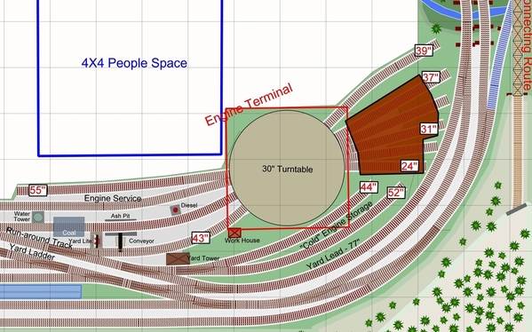
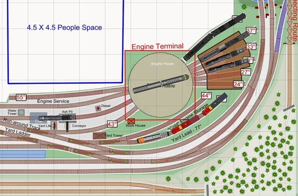
After adding another whisker track off of the turntable (encroaching into the aisle space a bit more), I produced this pic of the engine terminal, with lengths of the engine tracks marked.

Ricks-EngineTerminal

Attachments

Images (1)
  • Ricks-EngineTerminal
Last edited by Ken-Oscale

Zoomed-in views of the two towns:

Ricks-LeftTown_V7hRicks-RightTown_V7h

Coal for steam engines is only available in the engine terminal.   But water (which steamers use more quickly) is also available in the two towns, situated for passenger trains (running the inside route) to stop at a station and also position the tender at a water tower for a quick top-off.

I have positioned one water tower for the outside route, near the turnout serving the mine.   If a train needs to stop here for water, a following train can use the cross-overs as previously described to work around.

Attachments

Images (2)
  • Ricks-LeftTown_V7h
  • Ricks-RightTown_V7h
Last edited by Ken-Oscale

Hey Ken. I have been enjoying this thread. Your plan looks great....it is exactly what I would do in that space. Stretch it out and run trains!! That is what my new layout under construction is like. Just my opinion, I am not a fan of prototype operation or switching out industries. I like to sit and railfan on my layout.

I have one suggestion since that is the purpose of your post. 

Every time I look at the plan....I tend to focus on the engine service area. For the size of the room and proposed layout, it just seems a little small crowded into that corner. I understand the location next to the yard (which I love the design, BTW) but I am not a fan at all of the curved "whisker tracks" leading into the turntable, engine house and storage. You do not have a straight run into the table anywhere.

That 24" long turntable seems a little small too for such a large layout. You have an ash pit so I assume there will be steam on the layout. At 24", I am sure you realize that only the smaller steam engines with tenders will fit. No 4-8-4 for sure. Also, I do not think a scale size set of "F" units in "A-B" configuration will work. I measured my Lionel F3A with F3B and they will not work.

On my old layout I had the same "curved" tracks leading in and out of the table and they were a constant source of problems for me, especially with steam engines. Also having those curved tracks going into the engine house are also problematic I think. Is the 3 stall house shown "custom"? Is so, I would have it built with wider doors just in case. 

OK...that is my critique..here is a suggestion. I would consider adding a peninsula out into the room to "feature" the engine facility. I know this takes up valuable floor space but I think it is possible and still have access all around. Your aisle space in that corner may be compromised and less that 36". However, such a grand layout deserves a grand engine facility...just like that fabulous yard and mainline. 

Maybe consider a transfer table instead of a roundhouse?  My old layout featured in Run 255 had the turntable and roundhouse. I was never happy with the design. However, this time around, I am going with a Millhouse transfer table. For me, I basically run diesels so not that big of a deal. With the table I am able to incorporate (2) repair shops plus a number of storage tracks. 

I draw all my plans with my CAD programs, either AutoCAD or Microstation so I do not use the available software that a lot of guys use on the forum. 

All of this is just my opinion, I think your friend is lucky to have someone like you to help him out. Thanks for sharing your design.

Donald

Donald, thanks so much for your post, you make excellent points.   In particular, I share your caution about curved whiskers.   There are two straight whiskers, and two sharp ones at O-72, and the others are much broader.   I will look at this again, so see if I can work in a straight lead of 6" or so for each of the curved whiskers.

I appreciate your comment about the size of the turntable.   I have been looking at Millhouse River Studio's turntables, but boy, are the expensive!.   I will think about a larger turntable, and using more of the aisle "people" space, but that space is also a priority.

Great post, many thanks -Ken.

Hey Ken. You are welcome. Yes...it is very tough to squeeze everything together even with such a large space to work with.

I agree, the Millhouse stuff is expensive, no getting around that. But Al builds a bulletproof table and in this case, you certainly get what you are paying for. It would be an investment I would consider for this large layout.

A layout this size will certainly run into the $1000's for lumber and track, even with doing all the construction yourself. With that price point, I would figure out a way to finance a fully indexed Millhouse turntable. Again, just my two cents.

Thanks for the reply and good luck with the design and ultimately the layout construction. I cannot wait for progress pics.

Donald

So here is a possible version with a 30" turntable.   Not sure how much of an investment in space and $$ Rick wants to commit to this feature, but it could work like this.   Four of the whiskers are straight.   There is 18" of straight on the lead to the turntable.   Other whiskers have six or nine inch straight leads.   Gentle curves.    Interesting problem, may try another version later.  Access/reach and the aisle are definitely compromised in this configuration.   -Ken

Ricks-O_GG-Ross_V7iRicks-EngineTerminal2

Attachments

Images (2)
  • Ricks-O_GG-Ross_V7i
  • Ricks-EngineTerminal2
Last edited by Ken-Oscale

Excellent Ken. Great design work. Now, it makes more sense for using lash-ups or larger steam.

I like it. A lot.

Hopefully Rick agrees and sees the benefit of a larger table while sacrificing a little space and a longer reach!!!

A layout like this is an investment for a long time and certainly not built on a whim. Factoring in the price of a 30" table over the life of the layout should be a moot point in my opinion.

Donald

This looks like a spectacular layout in the planning! I am an S scale operator and have a medium sized custom layout with 18 months of operating experience with it. I offer the following thoughts on the plans. My minimum radius curve is 30" which scales to O-80 in O gauge, about the same as yours. We adjusted the track plan to include easements. If longer cars and engines are in your fleet the easements minimize the lurching as they enter the curves. We also deleted all the #4 turnouts in favor of #5 minimum, even in the freight yard ladder. I feel the trains look better and seem to operate better.

It looks like there are no reverse loops in the track plan. My original plan had none and I thought I did not need any but the plan was modified to include some. I am surprised how frequently I use them now that I am operating the layout.

My S scale turntable is 22", the same as 30" in O scale. As people recommended above, this is a good size, but it will still be a little short for the largest articulated steam engines. Be careful starting a curve on the approach to the turntable, a short length of straight track is desirable.

I can only wish I had as much space as you have. I hope you enjoy the layout for a long, long time.

Thanks AmFlyer, and I appreciate your comments.  In particular, your suggestion about easements - I am a strong advocate for easements whenever possible, and have incorporated them in this plan and in my other designs.   So I took another look through the design.   The minimum curve specified by Rick was O-72, but I thought that for running long passenger trains we should look at a wider minimum, so I went with a wider minimum of O-80 for the mainlines.   I have circled the two sections on the mainlines that are AT this greater minimum, these can't be expanded without compromising the length of sidings and switch leads.   Everything else is already wider than O-80 - at least O-89 - so pretty good!

 Mainline cross-overs are #8 and O120-O96 curved: wider minimums.   There is one #6 cross-over at the junction with the branchline or connection at the left.   So these minimums are pretty good for mainline passenger trains.

The "High Line" is minimum of O-72 by intention, to look more like a winding branch line, but with O-80 easements, or are even wider curves than that, so this meets and exceeds the standards.  I did go over the High Line and replace all the turnouts with #6s - there was room without compromising any other aspect of the design, so I thought - why not? - though perhaps the #4s might look better for this winding branchline concept.

For comparison, I have shown how the yard ladder would look with #6s (Ross doesn't offer #5s), and you can see it would alter the yard dramatically, and unacceptably in my opinion.   See what you think.   Regards - Ken.

Ricks-O_GG-Ross_V8a

Attachments

Images (1)
  • Ricks-O_GG-Ross_V8a
Last edited by Ken-Oscale

One more tweek:  on the left side mainline above the elevator, there was a broad reverse curve where the mainline curve connects to a right-hand #6 for the junction cross-over.   I worked in a O120-O96 curve instead for the junction, eliminating this reverse curve, but separating the cross-over from the junction turnout.   This allowed me to ease the junction departure angle underneath the bridge, now its almost a straight-shot.

Ricks-O_GG-Ross_V8b

Attachments

Images (1)
  • Ricks-O_GG-Ross_V8b
Last edited by Ken-Oscale

Hey Ken. Just an fyi about the yard switches.

I have used ROSS #4's for a long time on my old layout and then again for my new one under construction. I never had a problem with operation, either the locomotive or cars. One advantage we have with 3 rail track and O Gauge is the fact there is a lot of "forgiveness" in the tracking or interface between the wheel sets and the rails. The guys with the smaller scales have to be a little more exact, so to speak.

I use ROSS #6 for my crossovers, I never used a #8. I also use their "REG" switch for crossovers too. They are an 11 degree angle and when spaced properly between parallel tracks, work just fine, even at higher speeds.

Just my two cents. I was sitting here enjoying my cup of coffee before the CEO / CFO wakes up and reading the forum.

Have a good day.

Donald

Ken, I agree with your comment that #6's in the yard take up way too much space. I used #5's. Donald made a great point about the forgiveness in 3 rail operations compared to 2 rail. My track will allow either scale or highrail equipment to operate so tolerances are very tight. The minimum #5 turnouts make the yards accessible to many of the scale wheeled engines. I think the layout looks great as you have it now.

One area I would look at further is the yard to turntable to roundhouse area. All my roundhouse stalls are 23" deep, exterior tracks at the roundhouse vary from 20" to 12". Upscaling by 64/48 gives 30" in O scale, with a shortest of 16". If there were 4 stalls, 2 could be shorter. I can get engines longer than the turntable into the roundhouse because all 3 of the turntable approach tracks line up with a roundhouse stall track allowing engines to be driven directly across it into 3 of the stalls without the need to rotate the turntable.

I have 3 approach tracks to the turntable, two start from a main line, one from a tail track in the freight yard. I find when operating the layout I use the main line approach far more often that the freight yard approach. That might just be my operating style. If I had any great suggestions for how to improve the roundhouse area I would share them but so far I am stumped on how to get more space there.


I remain uncomfortable with the amount of space the engine terminal takes up.   So I thought the two left long whiskers, one could be deleted in favor of two new "cold" engine storage tracks.  

My thinking is that one purpose of the engine terminal is to service and ready locos, and the other purpose is to store locomotives not needed for the next trains outbound.   This terminal allows seven or eight locos on the "ready" tracks or in the roundhouse, and another three in the storage tracks.   (A natural place for diesels, which never really go "cold" as steamers do.)   So that is 11 locos in the terminal, plus a switcher on the run-around tracks, plus perhaps another six locos pulling trains around the layout (two on each mainline):  18 locos easily:  16 on the mainline, and two on the "high line".   Not counting the turntable lead track and engine service track, which are available for loco movements.   Then there is "off-line" storage for locos on the car shelves at the far left, which can be loaded/unloaded using the connecting RR track.

Ricks-EngineTerminal2

The turntable whiskers are at 15 degree angles.   I wonder if for a 30" turntable, can these come off at smaller angles - is this configurable by the builder?  Is so, the facility footprint can be compressed a bit more.   

Attachments

Images (1)
  • Ricks-EngineTerminal2
Last edited by Ken-Oscale

Hey Ken. Not sure if the plan is to purchase a quality roundhouse or scratch build. However, now is the time to decide. Once construction starts, no amount of tweaking will make it all fit unless the correct dimensions and locations are first determined, based on the building and location.

I can vouch for Dennis Brennan's beautiful roundhouse that he offers for sale. His website contains a ton of information of the proper geometry and dimensions for placement of the roundhouse in relation to the centerline or the edge of the turntable. I suggest you check that out.

Also, Bob at Altoona Model Works makes another impressive roundhouse to consider. He also can supply pertinent information concerning building set-back, etc. if you purchase one of his kits.

Finally, on my old layout.....I built an old Korber 5 stall kit with extensions. It was an old kit from the very beginnings of Korber and did not go together too well. I never took into account the correct set-back locations and my whisker tracks never followed the contours of the building since I crammed it into a smaller space that really required. Somehow I was able to make it all work but not without a lot of cussing in the process. However, once Rich and ultimately Mr. Muffin has taken over, there kits are a whole lot better and actually fit together. Just follow the instructions.

Al at Millhouse Studios can supply drawings that show the proper relation between his turntables and a roundhouse. If I remember, they may be based on a Korber kit, but I am not all that sure.

I know this is a lot to consider in the design stage but it is important to do so it all fits together in the end.

I do like your current design for the engine service area...you did a good job.

Donald


Thanks for that information Donald!   Rick is still considering some of these issues.

Assuming the turntable is configurable, I looked at a spacing of 7.5 degrees on the 30" turntable to see what that might look like.   Larger set-backs so that locos don't rub elbows of course, but more whiskers, and a big saving in footprint.   Ties may need to be trimmed, but the rails don't come close to overlapping.   I am careful about intruding into people space - if you look around the layout, there are plenty of places where the aisle space is just 36", and not much larger spaces for folks to congregate.   Rick and operators need to feel comfortable and enjoy moving around the area, and not feel "boxed-in" to a confined space, which can detract from enjoyment.   My opinion in the design.   Anyway, here is what something along these lines could look like:

Ricks-EngineTerminal3

Attachments

Images (1)
  • Ricks-EngineTerminal3
Last edited by Ken-Oscale

Here is how I am looking one of the design criteria:  a comfortable space for operators.  There are only three areas where folks might easily congregate, or where someone might pull up a chair to railfan while others operate the railroad.

The layout could easily support seven operators (six engineers and one yardmaster/hostler) in an operating session, some following trains clock-wise, and some following trains counter-clockwise, moving past each other.   And if you add in one or a few visitor/wife/kids and you can see that the space for folks becomes a premium.   Rick may want to host an open-house at some point, which could get even more crowded.  Its a big and wonderful layout space, but we have done well in filling it with railroad, not wasting any space at all .  

The "dead-end" by the turntable and connecting RR junction is a space where folks need to not just shoulder-past each other, but have to actually turn around to continue in the opposite direction - needing more space than just an aisle.

Ricks-O_GG-Ross_V8f

Attachments

Images (1)
  • Ricks-O_GG-Ross_V8f
Last edited by Ken-Oscale

Ken, great layout design!  I just have two suggestions regarding your latest engine service area revision:

  • Be careful you don't crowd things too much in terms of the roundhouse footprint.  You're already into "custom" dimensions territory given the current set-up.  And you could find you need more of a set-back from the turntable to the roundhouse front-doors, in which case you might perhaps decide for just a 3-stall roundhouse. 


  • Secondly, turntables tend to come as a SQUARE assembly.  Check with Millhouse and/or Ross, and you'll see what I'm referring to.  So while you might want the benchwork to be contoured to the curved portion of the turntable, that might not be an option given how the turntable assembly is constructed.


Just some things to think about.

David

David, thanks so much, and excellent point on the square turntable shape, I had overlooked that requirement.  The square can be angled of course to align with the benchwork edge.   I will look at this aspect.  Here is a roughed-in (not precise measurements) space for the square turntable, just to see.   Aligned with walls and grid seemed to be the most optimal rotation.

Ricks-O_GG-Ross_V8f

Attachments

Images (1)
  • Ricks-O_GG-Ross_V8f
Last edited by Ken-Oscale
Rocky Mountaineer posted:

  • Secondly, turntables tend to come as a SQUARE assembly.  Check with Millhouse and/or Ross, and you'll see what I'm referring to. 

The Ross turntable comes mounted on a square framework.  The Millhouse turntable is round with some flanges underneath to mount it to the layout.  You will need a couple of inches of table top beyond the turntable pit so the flanges can be secured in place. 

Also, you will not be able to fit as many tracks into a roundhouse as close to the pit as you have drawn.  There needs to be clearance between the tracks at the roundhouse entrance so that 2 locomotives can clear the roof support post.  It's really easy to be too optimistic in terms of what will actually fit when drawing plans.

Clem, I appreciate your comment about O-96.   I was wondering it it was possible, well it took some time and changing #8 cross-overs for #6, but it works.   Nice!!  O-96 minimum for both inner and outer mainlines.   Three of the curves were already O-96, and it took some work to reconfigure to adjust the final three.   People space on the right end got 1/2' larger.

Bob, thanks for your comments.   The enginhouse is just for concept/ideas, I will leave it to Rick to decide how he wants to handle this.

Ricks-O_GG-Ross_V9b

Attachments

Images (1)
  • Ricks-O_GG-Ross_V9b
Last edited by Ken-Oscale

Had not really done much with the High Line to this point.   I added a passing track at the top-right on the curve, so that trains could run in opposing directions and pass each other at the two passing tracks.   Check the clearance of locos and equipment, the curves here are broad, but the center-rail separation is 4 1/8"- no modern auto carrier cars here.   I imagine short cars and small steamers.

I also added another siding on the left, with a water tank, coal loader, whistle-stop station and an access road.

Perhaps a freight running clockwise, servicing the three industry spur trailing-point turnouts, and a passenger train running counter-clockwise.

Ricks-O_GG-Ross_V9f

Attachments

Images (1)
  • Ricks-O_GG-Ross_V9f
Last edited by Ken-Oscale

@Nittany Lion Engineer

I agree, these small tweaks that Ken has added really have me motivated!! I think this will be a great place to run trains, hang out, shoot the bull, and relax!

I'm already in the process of clearing the basement, and preparing for installation of a new ceiling, and upgraded electrical and lighting. I recently ordered a new storage shed to put things in, which will free up the entire basement for a layout. I'll enclose the utility area where the furnace is, drywall the outside of the stairwell, and put in some shelves. Then comes the electrical, ceiling, backdrop, bench-work, etc. It'll be awhile before the first track gets laid, but I have a plan! I think I'll lay in the upper main, turnouts, and sidings, before moving on to the lower level. I'll put in the lower mainlines and turnouts, and then get everything wired. After that, trains will be running and I can build out the yard, industrial area, and town as time and $$ permit. This way I'll be able to get trains running, and keep my enthusiasm up! Of course I'll need a lot of help from anyone willing, NLE!!
Rick

Ken

Love this thread. No comments from me here, looks like you have achieved all you need for FUN. When do you start construction as I cant wait to see a video pf trains running.

Not sure of you ever saw any video of Bob Bartizek's the Pennsylvania and Western, I have attached a link to one of his you-tube videos but for real enjoyment purchase OGR Video #11 30 minutes + is dedicated to this layout. What you are creating is close. 

https://www.youtube.com/watch?v=wO6m0wRSiOo

Steve, thanks for the video, I definitely see some similarities.   It would seem that Rick's layout has broader curves.  Bob has some outstanding scenery!   Interesting that Bob ended up with more operators than he originally thought would be sufficient.   For Rick's layout I would think 7-8 operators would be about all that could be kept busy.   -Ken

Great work, my only comment is based strictly on my personal preference to be able to run any given train anywhere on the layout. I would take that connecting rail spur on the bottom left and bring that up to meet the elevated track. Why have an interchange with a non-existant railroad when you have a completely separate line to interchange with?

I have to agree with you, METSNO1FAN, it would be nice to have the upper and lower mains connected. Ken and I discussed that, and I decided, against Ken's advice, not to do so. I went with the isolated upper main for the sake of simplicity, and out of a desire to have an upper level mainline. Now that the plan is essentially done, I can see where we might be able to come off the spur above the small town on the left, nearest the breaker box, and down-grade to somewhere along the lower outside main. This would allow access to the spurs on the upper main, which could provide coal loads and lumber, etc. to the lower level. I'd like to hear other opinions on how best to connect the upper and lower mains, if we decide to do so. One thing I don't care for is long sections of elevated track just to make the grade, especially when it makes access to lower level track, switches, and cars difficult.

Rick

To add to the discussion about connecting the upper and lower levels:  the upper level is currently planned for 7" above the main level.  Using the Woodland Scenics approximations used in their risers (i.e. 3% grade is 3 inches over 96 inches (8 feet)), then to make the grade at 3% for 7" we need 18.6 feet of grade.    A run at 2% would require 28 feet, perhaps undoable to fit in.   A run of 4% would require just 14 feet, but I think that 4% is too steep for long trains, but could work for short trains and could be a part of the fun action (dispatching a train able to make the run up the grade).   Depends on what Rick would like - I recommend a grade of around 3%, plus or minus.

Other options could include adding a grade on the double-track main line at 2%, in order to meet a gentle grade coming down from the High Line.   

A) I am seeing one place where perhaps this could be done with minimal re-alignment: along the left-hand side as Rick suggested, but instead curving off from the existing High Line in the tunnel in the upper-left corner, and running down to meet the main lines before the lift-out bridges.   3% or so.   Eliminating the current junction and connecting road due to clearance issues with the descending grade.   There may be other alternatives, this alignment just jumped-out at me.  

B) If 4% is acceptable, it might be possible (following Rick's suggestion) to branch off the High-Line near the water pipe and descend toward the top of the diagram, and toward the mains connecting at the curve before the trestle.   This might keep the existing connecting road and junction, which is useful for swapping cars and locos with the train storage shelves.   

C)  Option B, but with with the mainlines rising and falling at 1% or 2% either side of the new junction with the descending grade, so at the junction would be 1 or 2 inches higher than currently, which would then allow the descending grade to be between 3% and 3.5%.   Also changing the grade through the town.


Last edited by Ken-Oscale

Option A will require a good bit of re-alignment, after all, to make it work, but will result in a grade of just under 3%.

It just occurred to me that as this option will block the current connecting track and junction, it would be possible to run a connecting track off the High Line in the same alignment, but at 7" in height. 

Last edited by Ken-Oscale

There is another alternative Option D:  eliminating the passing track on the high line, near the power plant and farm, and replacing this with a track on a grade.   Coming off of the curving trestle at the mine, and descending to connect with the main line near the cross-over beneath the trestle.   This would be at 3.75%.   Less if we allow the mainline to rise up to meet the descending track.   I hate to give up this passing track that allows trains to pass each other on the high-line.

Rick could choose both Options C and D, with a double-cross-over beneath the High-Line Trestle, and have grades running in both directions.   So a train could ascend to the High Line and then descend back to the double-track mains, using the double-cross-over to preserve right-hand-running.

Option E:  Basically what Rick and I looked at earlier:   eliminate the passing and staging track on the High Line at the bottom of the diagram, with a connecting track (running either direction).   If Rick wants to preserve this passing/staging track, the yard could be pulled-out about five inches to allow a grade to connect the High Line and main lines.   Crunching the people space, unfortunately.

It seems that none of the options to far, are without trade-offs of some kind.

Yikes! Another idea Option F:, don't know if it is tough to visualize:  At the bottom of the diagram using the turnouts at BOTH ends of the High-Line passing track to instead begin a descent toward each other.   Where these two tracks meet at 3.5" in height, connect them with a double-slip switch, so that each direction can then continue down to the mainline.   Grade would be about 2.5%.  Would be interesting to see and use!  This alignment could still be used as a passing track on the High-Line, where a train dips down to the double-slip, and then rises back up.      The double-slip switch most likely needs an approach track in all four directions closer to level, for reliable operation, a vertical grade easement of say 1%, which would drive the rest of the grade up to nearly 3%.

Last edited by Ken-Oscale

I am leaning toward this solution for a single connecting grade and junction between the High-Line and the mainlines:

Ricks-HighLineJunction_V10d

This junction design preserves all of the good features worked in so far (passing tracks and the connecting road junction).   The new curved turnout making the connection, is level at 1-1/8" elevation, with grades of about 1.75% on the outside mainline between the new turnout and the cross-overs in either direction.   The slope from the new curved turnout up to the high line is 3.7% - perhaps OK for this operation.  The turnout length is about 2', so that is a level spot of about 2' between grades.   

On the inside main on the parallel curves, I brought the line up to 1/2" in elevation, with grades of about 1.1%, so that the terrain slope continues from the high point above the tunnel down through the three tracks each at a different level, then following the stream to the switching lead serving the town.  The switching lead (now 39" long) descends to -1/2" in the town itself (at about 1.5% grade), for a pleasing and convincing look to the scene.

Jan, there is already a mine on the High Line, near the connecting road track.   Rather than mining coal, I thought that perhaps the railroad would benefit from some diversity, with some other ore - perhaps copper.   Then in the far right town, a small smelter operation could be added to receive the ore (where the Morton's Salt tower is currently).   Giving a reason to move trains from the high line to the main level.

With just a single direction connection, and no way to turn trains on the High Line, trains will have to back down the grade at some point, or use one of the passing tracks to run a locomotive around the train, so that the engine descends at the head of the train.   Adding Option D will solve this problem, and it would seem to be possible to preserve the passing track, by angling and pulling the mainlines toward the aisle, at the expense of the farm, so as to stay within the current benchwork limitations without compressing the aisle.

Attachments

Images (1)
  • Ricks-HighLineJunction_V10d
Last edited by Ken-Oscale

Looks like a good solution, and the fact that the engine will have to run around the train should be no problem. Very prototypical.  However, if Rick intends to run steam locomotives it would, if I'm understanding this correctly, require him to attach a coupler to the front of the steam locomotive.  Hmm.....Maybe a scale kadee like used on the Black Diamond that would also grab a regular coupler.  I think that this animal exists.  Of course I could just be delirious, I do need coffee.

You might enjoy a short look at a pre-civil war iron furnace, used during the Confederacy, and destroyed by the Union, not far from where I live, not too far from a CSX main line.   Just the furnace remains, not sure what buildings would have been constructed.   This could be an idea for an industry to process iron ore from the High Line mine (depending on the era Rick wants to model of course, perhaps updated for a more modern industry).

Cooper Furnace Historical Site

Finally getting started on the layout that the very talented Ken Hoganson designed for me! Thought I'd start adding progress updates to this thread as things... progress.

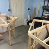
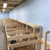
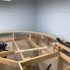
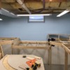
Due to budgetary constraints I decided not to undergo any major basement finishing, and get rolling on the benchwork etc. The walls will have a simple backdrop installed to improve appearance, the floor will get a cushy, interlocking, foam tile type covering, and the studded walls around the central staircase will also be covered for a more finished look. Lighting is nice and bright with LED shop lights  providing illumination. The attached photos follow the benchwork as it proceeds around the perimeter of the basement. There are no duck-unders needed as the stairs come down away from the walls. The open area in the benchwork, near pictured the door, will be home to three bridges that will lift out for access to that exterior door on the rare occasion we need to use it. The long stretch of brenchwork with the elevated line will be widened to provide more layout space as required.

The last photo shows my roadbed and track- 1/2" plywood, 1/2" homasote under the track only, with Woodland Scenics foam roadbed, Gargraves track, and Ross switches. Using only adhesive caulk to attach roadbed and track- no screws. Preliminary tests have shown this to be very quiet and stable.

I have a long way to go, but as an old friend once told me, "Just get started, do it before you get too old and can't". There was a much longer, philosophical conversation revolving around that subject, but that was sound advice to someone who tends to have "paralysis by overanalysis". He has since passed on, but his words still inspire me. This layout is dedicated to him. Rest in peace, CSM Paul Rausch, you are missed.

Rick

Attachments

Images (14)
  • A: Future "industrial" area
  • B: Trestles and mine scene
  • C: Trestles and mine scene
  • D: Dramatic bridges and mountains will go here, at bottom of entry stairs.
  • E: Wide section for small town, with space behind for electrical access and storage
  • F: Wide section with space behind for electrical access and storage
  • G: Location of lift out bridges for access to exterior door and storage
  • H: Location of lift out bridges for access to exterior door and storage
  • I: Lower level here will be widened by ~1ft to accommodate yard and passenger tracks
  • J: Lower level here will be widened by ~1ft to accommodate yard and passenger tracks
  • K: Upper level curve at end of yard area
  • L: Upper level curve at end of yard area
  • M: There will be a river here, with bridges connecting yard area to industrial area
  • N: Example of roadbed
Last edited by ricka1

I know you decided not to finish the basement, but you will get a LOT of dust filtering down from those exposed insulation batts up above.  Some drywall (it can be the 3/8" stuff, easier to lift above) screwed to the joists will make you a lot happier later.

Nice clean benchwork installation by the way! 

Add Reply

Post
The Track Planning and Layout Design Forum is sponsored by

AN OGR FORUM CHARTER SPONSOR

OGR Publishing, Inc., 1310 Eastside Centre Ct, Suite 6, Mountain Home, AR 72653
800-980-OGRR (6477)
www.ogaugerr.com

×
×
×
×
Link copied to your clipboard.
×
×