Don,
If you are wanting a kit from this thread: Design of a $10-20 DCS-TIU Port Tester Tool? send me an email.
I have 4 orders toward the the next order of those kits and need 8-10 total before ordering stuff for the next batch.


|
|
Don,
If you are wanting a kit from this thread: Design of a $10-20 DCS-TIU Port Tester Tool? send me an email.
I have 4 orders toward the the next order of those kits and need 8-10 total before ordering stuff for the next batch.
You guys really should do this in the other thread. ![]()
I'm trying to move the TIU test folks back over there! Been leaving a trail of links... ![]()
While I'm here, did I miss a kit or something for the TIU protection work going on over here?
SWISE asked if he read using PSX-AC's damage a TIU? I must have missed that in this long thread and really don't want to go back and read through it all. Can someone verify this ?
It's in Adrian's beginning post if you want to read it and make up you own conclusions. I didn't read it as the PSXs caused specific new (or any other) damage, just that they didn't solve the problems Adrian was working on?
Probably best to hope Adrian answers your question, but he recently said he was out of town on a work assignment for a while.
Dave Zucal posted:SWISE asked if he read using PSX-AC's damage a TIU? I must have missed that in this long thread and really don't want to go back and read through it all. Can someone verify this ?
It's complicated but let me try to recap in a short post.
1. A PSX-AC protects circuits from over-current (melting down) but not transient over-voltage (being zapped).
2. This thread is about transient over-voltage causing the standard TVS inside the TIU to fail. The PSX-AC does not protect this. The transient over-voltages come from derailments and other ugly events. The result of the failure is reduced DCS excursion voltage on the digital square wave.
3. If you have inductive chokes between the power supply and layout to boost the thevnin impedance and improve the DCS signal, the abrupt current turn off when the PSX-AC trips causes a big di/dt voltage which can damage the standard TVS similar to a derailment. Again the result is reduced DCS excursion voltage.
In either case the standard TVS is not enough to absorb hits (at least in my club). We have modified the TIU with a different TVS and added silicon clamps, and now our club layout has not had a single channel degrade in almost a year since we started the work.
Thanks Adrian for the summary.
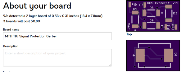
I came up with what should be an easier fix for the TIU protection that embodies the principles outlined by Adrian in his original fixes. It's a small board that you stick directly to the top of each ACT244 chip and wire four leads directly to the chip. By jumpering four wires from the pads on this board protection to the chip below, you can provide transient protection for the ACT244 driver without removing the board from the TIU, all work is from the top. I actually use a spot of adhesive on the large TVS chip on the bottom to secure this board to the ACT244. Note the numbered pads, P7, P10, etc. Those correspond to the pin numbers of the ACT244 chip.
I've previously made the PCB files available, and can do so again.
Here's the details...


Given the small size of the board, you can get them made really cheaply, OSHPark only charges 80 cents for three boards. I recommend specifying the 2 oz copper, 0.8mm thickness option, you get lower impedance traces and a slimmer footprint for the board.
Here's the files necessary to order boards.


I looked early on in what Adrian was posting, but I've never seen any one from MTH getting involved with this on going problem arising from the MTH Equipment......?
Have I missed some input from them or what ....???
John, Protection would be great, Wondering does this hold up to repeated occurrences or hard shorts, ie dead short derailments, metal screw driver dropped across rails ? Long enough for other protections to perform, ie Z4000 circuit breakers or TIU circuit breakers to trip, or is a there another protection that could be installed that is faster acting? Thanks for all yours and Adrians work on this project, I believe I have a couple of TIU's with problems
Deano
Deano,
Hard to say without more testing, but I used a very robust 1500W TVS in the design specifically to avoid the issue of the lower rated ones getting zapped by whatever was happening.
If your TIU already has issues, you need to do a repair before adding the protection. I presume you've seen the thread on the TIU tester project, and of course you can verify signal levels with a 'scope.
Yes I have been following both, this thread, the tester thread(I have one on the way) and the TMCC Buffer, as I would like to have all the above protected and functioning. Just thought I had read something about fast trip protection.
Thanks again Deano
RWDeano posted:Yes I have been following both, this thread, the tester thread(I have one on the way) and the TMCC Buffer, as I would like to have all the above protected and functioning. Just thought I had read something about fast trip protection.
Thanks again Deano
Hey,
It's not about "too much current" so fast breakers, or super fast breakers, or fuses won't do anything on this issue. The issue is the very very high di/dt voltage (inductive kickback) that's generated from current discontinuities the layout inductance, wiring inductance, and explicit signal transfromer inductance which zaps the existing TVS and eventually ACT244 drivers.
This fun thing describes it well.
That was why I tried to go to a significantly larger TVS, and the diodes are to minimize the shunt capacitance.
Hey Adrian, does the old QSI PowerGuard units, which protects against voltage spikes, protect against this "very very high di/dt voltage (inductive kickback)"?
Thanks,
GRJ,
Thanks for the post above and the gerber files. I think I will try that too. Good tryout for surface mount PCBs, plus you get 3 to practice with! Maybe next week I can take a good look at my TIU and see what all it has on it. It's a Rev L and I think it's a pretty early version of it too.
Not sure how I missed that earlier, but it slipped right past me? I think you guys are typing too fast again... ![]()
RTR12,
I was also thinking about trying this project. but I've never tried to solder surface mount parts. Do you have any good tips for the best way to do it?
Brandy,
but I've never seen any one from MTH getting involved with this on going problem arising from the MTH Equipment......?
Take a look at this thread regarding MTH's involvement as regards this issue.
rtr12 posted:GRJ,
Thanks for the post above and the gerber files. I think I will try that too. Good tryout for surface mount PCBs, plus you get 3 to practice with! Maybe next week I can take a good look at my TIU and see what all it has on it. It's a Rev L and I think it's a pretty early version of it too.
Not sure how I missed that earlier, but it slipped right past me? I think you guys are typing too fast again...

Order at least two sets, there are four ACT244's that need the protection. At 80 cents for three, you can afford to be generous. ![]()
johnf posted:RTR12,
I was also thinking about trying this project. but I've never tried to solder surface mount parts. Do you have any good tips for the best way to do it?
My "simple" way. I tin one of the pads, and then use the tweezers to position the part and heat the tinned pad and position it. Then I solder the remaining connections. I try to lay out any boards so that I can easily do the hand soldering. I also clamp the board so it won't move as I'm working on it.
Thanks GRJ. This will be a good project to practice on. The price of failure is pretty low.
Yep, if you check the BOM parts, all of them for one board should only be a couple of bucks. Buy enough for at least four boards so you can equip at least one TIU.
Let's see. I blinked and since, to use rtr12's expression, you guys type too fast, I've missed quite a few posts. Initially, a service bulletin was issued calling for addition of 4 TVSs to a Rev L TIU. Then Adrian found that solution doesn't do the job. So GRJ has concocted a new fix which calls for a board to be fabricated and then added to the ACT244s, with the recent-fix TVSs removed. Did I get this fairly straight?
rtr12, are you going to produce kits for this also?
How can OSHPark make money if it's 80 cents for 3 boards?
GRJ, I felt bad about the order only being 80 cents, so I got a dozen for $3.20. Then I ordered parts and wished I would have only gotten 6! ![]()
Oh well, I need the practice to learn this anyway... I may ruin a few PCBs and parts too, you never know? Learning expenses!
JohnF,
I have never soldered anything surface mount before, so I am also following GRJ's advice above. I have seen a few folks soldering these things on youtube and if I recall they were also using GRJ's methods.
RJR posted:How can OSHPark make money if it's 80 cents for 3 boards?
Not my problem, they set the prices, I pay the prices. ![]()
![]()
Tom, I'll by the other 6 if you want to sell.
And the components if you want to get rid of them.
RJR,
I defer to GRJ as it was his design. But, if he doesn't mind, I have 12 PCBs and parts ordered and you are welcome to 4 of them at cost for parts & shipping. I didn't figure out you needed 4 per TIU until GRJ's later post above, I was thinking (or not thinking) only one was needed, duh!
Edit, make that 6. I only really need 4 as I have only 1 TIU. That is if my soldering is successful.
"I tin one of the pads, and then use the tweezers to position the part and heat the tinned pad and position it. Then I solder the remaining connections."
GRJ, years ago, when I had to solder components, I was advised that soldering heat would damage them and to always use a clip-on heat sink. Are these surface mount components less susceptible to heat damage.
Not to complicate matters but the TVS that grj uses is a lot bigger than mine so the capacitance in the unavalanched condition will also be a lot higher and load the DCS source.
It’s probably okay but has anyone taken scope measurements with it? Seeing thinks are okay is always better than expecting them to be....
Adrian, that's why the diodes isolate it from the pins, I thought that's what we discussed. ![]() With normal signals, we're just dealing with the capacitance of the diodes.
With normal signals, we're just dealing with the capacitance of the diodes.
gunrunnerjohn posted:Adrian, that's why the diodes isolate it from the pins, I thought that's what we discussed.
With normal signals, we're just dealing with the capacitance of the diodes.
Right I remember now!
should be good
RJR posted:"I tin one of the pads, and then use the tweezers to position the part and heat the tinned pad and position it. Then I solder the remaining connections."
GRJ, years ago, when I had to solder components, I was advised that soldering heat would damage them and to always use a clip-on heat sink. Are these surface mount components less susceptible to heat damage.
I've soldered tons of SMT devices, and I haven't damaged them with the heat. Remember, you have to have solder right on them as they have no leads! ![]() FWIW, I don't routinely use a clip-on heatsink for thru-hole parts either, most of them are rated for up to around 10 second of soldering temperature as well. If you need a heatsink, how do you wave solder a thru-hole board?
FWIW, I don't routinely use a clip-on heatsink for thru-hole parts either, most of them are rated for up to around 10 second of soldering temperature as well. If you need a heatsink, how do you wave solder a thru-hole board?
One key element of soldering any electronic part that could be sensitive to heat is the soldering iron temperature. .63/37 solder melts at 361F, I usually use an iron temperature of around 500F for those jobs. When I make my little flickering firebox modules with the flickering LED's, I've found that I need to reduce the heat as much as possible to avoid killing the flickering LED, 450F is what I use for those.
Adrian! posted:gunrunnerjohn posted:Adrian, that's why the diodes isolate it from the pins, I thought that's what we discussed.
Right I remember now!
should be good


gunrunnerjohn posted:Yep, if you check the BOM parts, all of them for one board should only be a couple of bucks. Buy enough for at least four boards so you can equip at least one TIU.
I got 15 of each item for 12 PCBs. Came to $23 before shipping and tax. I picked USPS 1st class ($3.75) for shipping, don't onow what tax will be?
Digikey told me that 100 of the D2-D5 items was less than the 60 I ordered so I went that route on those. It was like $1.60-$1.80 less or something like that.
Also if you don't mind I would be happy to let RJR have the others I don't use. I don't feel right about doing things like that without the designer's permission.
It's released for public consumption, you can do with it what you will. ![]()
GRJ, you asked, "If you need a heatsink, how do you wave solder a thru-hole board?" Short answer is, I don't. In fact, I had to look up "wave solder" to see what it meant. I did use heatsinks recently when I made up supercaps for PS2 by soldering old MTH battery leads/plug to them, to avoid damaging the supercaps. Now you bring me into the 21st century by saying that was unnecessary. That's my new bit of knowledge for today. (Yesterday's was the difference between allision & collision.)
Noting rtr12's last comment regarding designer's permission, he has a good point. I recommend that if you ever think that you're going to produce kits yourself, you so state.
I am not going to make TIU Protection Module kits. ![]() I reserve the right to make some of these for myself.
I reserve the right to make some of these for myself. ![]()
Thanks again, GRJ. I thought it might be ok since you posted the file here, but I feel much better now that you've said it was ok. ![]()
Also, thanks for the temp tips for the surface soldering. That's good info to have.
RJR, you can have the rest after I get mine made. I have a few extra parts and 3 more boards is only 80 cents so I would be willing to get you more if need be. I am thinking you have more than 1 TIU? Also OSHpark takes about 2-3 weeks if I recall the last order I got there.
Robert,
Now you bring me into the 21st century by saying that was unnecessary.
Didn't we discuss that in a previous (voice) conversation? Regardless, I built all 50+ of my supercaps without using a heat sink and had a 100% success rate.
Access to this requires an OGR Forum Supporting Membership
