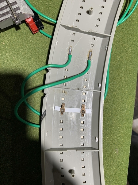
Observation: S FasTrack does NOT have the convenient electrical connection blades on the underside, which O FasTrack has, allowing any section to be a power drop.  Too bad, that is a step backward, but not as easy to manufacture because the rails are solid, so understandable.  I have one 10" power terminal section which is doing fine for now, no drop in voltage detected so far.

Because the rail joiner "fishplates" are braced and enclosed by plastic to help them keep their shape without spreading, it would be difficult to solder a feeder to rail joiners to serve as electrical connections.   

Last edited by Ken-Oscale

Ken, I have some FasTrack in a set but never used it. I do have a lot of the SHS track which uses the same .138 rail. The SHS track has a tab that protrudes down under the track from each rail joiner. This allows connecting a power feed to each rail joiner if desired. I have a 5'x12' loop of SHS track on my office floor so I can operate some engines conventionally. It has just one feeder connection. If I run a Gilbert engine there is no doubt there is a voltage drop at the far end of the loop as the engine slows down. If I run Legacy engines in conventional mode there is absolutely no change in speed, same with a FlyerChief engine. The cruise control compensates for the one to two volt drop. Given you plan to use FlyerChief engines it is unlikely more than one track feed is needed.

@GVDobler posted:

Ken

Just curious if you tried anything like a dub of petroleum jelly to connect the S track?  I am considering an S layout after reading this thread.

No, I haven't tried that, perhaps that would help.

My filing-down of the circular bulbs that project into the receiver, plus a bit of trimming of the receiver, seemed to work.   I had to do every straight section, both ends, but got the process down to a science, maybe a minute with each one, so not too bad after all.  I used the edge of a knife scraping it along the plastic, away from the knife edge.  So not cutting into the plastic.  It didn't take much material removal to make a difference: lots of tiny scrapings, but I cannot see much deformation of the perfect circle of the "male" connector.

I also found a couple sections of straights had some flashing at the end, which I had to trim off.

The turnouts do not have the O FasTrack non-derailing feature.   The gate in the frog is a place where a short will occur, if running against the setting (I tried it, and got a nice spark, and the transformer rolled-back the current).   I think I can work up a detection circuit and a relay to switch the turnout automatically, an idea for the future.   So the turnout is switching the polarity of both the points and the gates and frog when throwing the turnout.   The entire turnout is "live", and the train does not hesitate with no "dead" rail sections, a very nice feature: no soldering of jumper wires or extra relays needed for electrical conductivity across the turnout.

Last edited by Ken-Oscale

I like the look of the layout and locomotive, its a nice change from O.   With this much running, its running perfect, these two turnouts work fine.   The "extra room" provided by the smaller scale looks very nice to my eyes.

I am returning the other two command-controlled S FasTrack turnouts to Lionel for replacement.

So the build is on hold until those are replaced.   Meanwhile, I can test out the Legacy command control of the turnouts. 

I can't recommend S FasTrack for a newbie or a kid, definitely "some assembly required" for me, and a tolerance for frustration, and being adaptable, and have some level of experience with model trains.   Three issues: the pilot truck on the loco, this batch of 10" straights, and the 50% failure of my turnouts.   But the result is very satisfying and enjoyable to run and watch.  The track and roadbed connections are all "perfect", no gaps.    So in spite of the issues, I intend to go forward with my build-out.

Last edited by Ken-Oscale
@AmFlyer posted:

Ken, I have some FasTrack in a set but never used it. I do have a lot of the SHS track which uses the same .138 rail. The SHS track has a tab that protrudes down under the track from each rail joiner. This allows connecting a power feed to each rail joiner if desired. I have a 5'x12' loop of SHS track on my office floor so I can operate some engines conventionally. It has just one feeder connection. If I run a Gilbert engine there is no doubt there is a voltage drop at the far end of the loop as the engine slows down. If I run Legacy engines in conventional mode there is absolutely no change in speed, same with a FlyerChief engine. The cruise control compensates for the one to two volt drop. Given you plan to use FlyerChief engines it is unlikely more than one track feed is needed.

Thanks Tom, I appreciate your experience!  I will likely add three more terminal 10" straights.

I looked at the rail joiners again, there is some exposure of the bottom of the joiner from underneath, but not enough to solder and attach a wire reliably.   The joiner doesn't want to pop out of the FasTrack, and looks like it would be hard to get back in.   It looks like the joiner end actually bends down 90 degrees into a slot in the plastic track piece.

I see a lot of engineering and manufacturing complexity ($ and time) in making the track sections and turnouts:  I appreciate Lionel "giving it a go", I respect the effort!

Last edited by Ken-Oscale
@Brendan posted:

I just elongated the slot under the rails and soldered wire there.  I tried to replicate the method used on the straights but it didn't hold up.

strack

Brendan


Good idea Brendan!   I would be afraid I would melt the plastic, but maybe I could pull it off without cold solder joints.

I could also try a small screw through the plastic to contact the underside of the rail.   Maybe.

Those pictures of the layout are interesting. 

When I first became involved with US 3RO, I was completely bewildered by the scale/semi-scale/O27 thing. There’s nothing like it, over here, and S Gauge never really existed.

Having now had experience of a “back of a door” O27 layout (6’6” x 3’0”) and comparing it to the pictures, and past experience of layouts of that sort in OO I can see how O27 developed, and why it maintained its lead over S Gauge. 

@Ken-Oscale posted:

I could also try a small screw through the plastic to contact the underside of the rail.   Maybe.

I tried that at first but the plastic isn't thick enough.  That is why I added the stryrene.  even then, it wasn't really good.  Maybe you'd have better luck.  Maybe build it up with a blob of epoxy; that might have the holding power.

Brendan

Last edited by Brendan

Continuing my build:  I connected my Legacy and Cab1L up, and tried the remote switching of the turnouts.  Some success, one of the turnouts I thought would be reliable is now hesitating when switching from straight to curved.   Sometimes I have to press the command button twice or three times, sometimes I have to move it by hand, and then it will switch OK a few times before getting "stuck".

[With all the problems with S FasTrack, one might almost think Lionel is trying to discourage folks adopting.   I went with S FasTrack because of the ability to run the turnouts in command mode.]

So I guess I will have to open this one up, to see if there is something binding in the mechanism.   I noticed that the turnout throwbar is slanted/cockeyed in between the ties, making contact at the switch stand end.   I may be able to trim some from the throwbar, if that is the issue.

When it works, it is great, to be able to switch my turnouts without the remote controllers and running wires to each turnout.

The full build, uses 16 turnouts.  At $83 each (not including shipping, etc), that comes to $1,328.  A significant investment.  But the turnouts just have to work, and they don't. 

Not sure where that leaves me on this project.  Right now, I have an oval with a passing track in 4'x7'.  I really don't want to quit on this, I am stubborn.

On a Positive Note: after a couple more hours running the loco, still zero problems, perfect.

Last edited by Ken-Oscale

My switches are R27.  I have 6 of them all purchased when they were first released.   All went back to Lionel for repair in the first year.  Problem was dead rails.  I also have had problems with some switches not responding with one push of the Cab2 button.  Makes it impossible to use the Route feature if it involved switches.  When one of the switches came back from repair and would no longer respond to Command Control I gave up using switches in Command mode. I think there are some real manufacturing problems with the R27 switches.

@JFC454 posted:

My switches are R27.  I have 6 of them all purchased when they were first released.   All went back to Lionel for repair in the first year.  Problem was dead rails.  I also have had problems with some switches not responding with one push of the Cab2 button.  Makes it impossible to use the Route feature if it involved switches.  When one of the switches came back from repair and would no longer respond to Command Control I gave up using switches in Command mode. I think there are some real manufacturing problems with the R27 switches.

Thanks for sharing your experience.  Not good news, but I appreciate it.  -Ken

Last edited by Ken-Oscale

I hate to pile on, but I have had the same experience with the turnouts.  I only had two R27 ones.  One of them just gave up the ghost, the other had the same or similar issue yours had with the throw bar.  It would wedge against the side and not complete the throw.  Not sure how it got that way; nothing appeared to be broken.  My two R20 are fine.  I have a mix of SHS and Fastrack.  I am now in the process of collecting Fox Valley track for my next venture.  Might use DZ2500s to throw them or servos/controllers connected to a SC-2. 

Brendan

Some good news:  after some more break in time, my troublesome turnout (of the two remaining out of four) is now working much more reliably.  I put both turnouts in routes using TMCC/Legacy.   While letting the loco run, I counted the successful operation of these two routes:

  • 32 operations:  3 failures to switch on the first command sent.   All three times the laggard switched after sending a single repeat. 
  • One derailment of the front pilot on the troublesome turnout, not causing any issues - the loco was slowed, stopped, reversed, and I manually re-railed the pilot truck.  This was the first derailment of any kind over a cumulative 7 hours of operation.
  • 65 operations:   One failure to switch at 59 operations, second command resent worked.
  • I made no changes to the turnout or positioning.

So, with this level of success, I am encouraged, and willing to take one more small step forward, by ordering two additional turnouts, while I wait for Lionel on replacing the two failures.  Order placed, hope for the best!

Last edited by Ken-Oscale

Lionel's reply on my request for a RA:

We do not provide outright exchanges, but we can bring your switches in for repair. To do so, we will need the product/SKU numbers, a receipt showing the date and location of purchase, your daytime phone number, and the best address to ship the repaired items back to you via FedEx with a required signature. At this time, repairs are being brought in in batches due to our closure from March-June due to COVID-19. If you are looking for an outright exchange, you would need to contact the dealer from where they were purchased.

Fair enough, I will try a scan of my receipt and etc.   Adds to the delay in getting these fixed, so I am glad I ordered two more, so I can make some progress.

The polarity detection and reverse unit should be showing up soon.  I will report results when that comes in.  I will need two of these for the full build.

Thinking about the turnouts in the "hidden" trackage.  Although easily reachable from the back/top, when operating the turnouts from the front of the layout, because of the reliability question, the operator needs to be able to see the turnout to confirm the actual position: either the points or the illuminated switch-stand.   

For one turnout, the operator may be able to see the position of the switch-stand in the dark tunnel by looking through the portal.   

The other two turnouts need some kind of indication of position:  I will have to think about that.  How to detect that actual position of the turnout points and gate, that might be difficult.   I suppose I could install a camera and have a screen to see inside.   I would probably need to be able to see the hidden trackage anyway, for moving trains and cars.

@Ken-Oscale posted:

Thinking about the turnouts in the "hidden" trackage.  Although easily reachable from the back/top, when operating the turnouts from the front of the layout, because of the reliability question, the operator needs to be able to see the turnout to confirm the actual position: either the points or the illuminated switch-stand.   

For one turnout, the operator may be able to see the position of the switch-stand in the dark tunnel by looking through the portal.   

The other two turnouts need some kind of indication of position:  I will have to think about that.  How to detect that actual position of the turnout points and gate, that might be difficult.   I suppose I could install a camera and have a screen to see inside.   I would probably need to be able to see the hidden trackage anyway, for moving trains and cars.

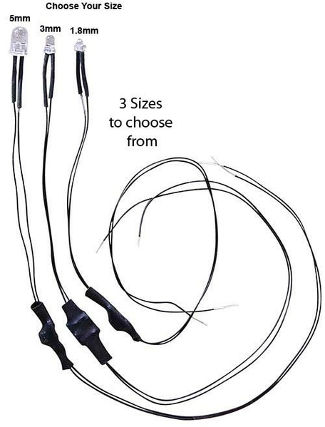
I wonder if the setting of the gate could be detected electronically, it will either have the polarity of the outside rail, or inside rail (however you want to label them).   Maybe connect a diode to the gate to yield a pulsed DC current, through a capacitor to smooth the current, and then to a transistor, that enables a LED. DetectCircutAC When the frog points to the diverging route, it is opposite polarity (black) from the rail (red), so current flows through the LED.  LED with diode and resistor to drop voltage to LED.  I have used Evans Designs LEDs in various colors "conditioned" so that you can connect them across an 18v AC power source, $3.25.   Evans Designs Universal 7-19v LEDs universal-solid-leds-for-transformers-30_540x

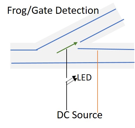
Perhaps instead, I could overlay a small DC voltage across the gate and frog just for detection purposes, and compare it to either of the rails to complete a circuit, and power a LED.   Its either the same as the rail (no voltage differential, or opposite with voltage and current flow).  I will have to look in the forum, this sort of thing has already been done.

Or just complete a DC circuit to light an LED:

Would it be this simple?    DetectCircutDC

Attachments

Images (3)
  • DetectCircutAC
  • DetectCircutDC
  • universal-solid-leds-for-transformers-30_540x
Last edited by Ken-Oscale

Ken, I will start by saying I do not have any of these turnouts and know little to nothing about their design. That said, is the failure of the points to throw a mechanical binding or a signal issue? Do the points move all the way to the closure rail or do they stop part way? The mechanical issues are repairable, there are some post on this on the 3 rail side, they may or may not not be applicable to S gauge.

If it is a signal issue then that should be an easy fix. I think the turnouts are using the Legacy signal off the rail connected to the Legacy base. If so I recommend a few .1microfarad 50V ceramic capacitors be used to put the Legacy signal on both rails. Then next the return through earth ground propagation can be improved. Connect a wire, any gauge, to the ground pin on the Legacy base power supply. Route that wire just beside or under the turnouts. That should fix any signal issues. The same fix applies if anywhere on the layout an engine loses the Legacy signal, that is indicated by a flickering headlight. I am pretty sure this is how the command turnouts are controlled. All of mine are hardwired from ASC2's so I do not have any signal reception issues but that is a more involved and expensive setup.

@AmFlyer posted:

Ken, I will start by saying I do not have any of these turnouts and know little to nothing about their design. That said, is the failure of the points to throw a mechanical binding or a signal issue? Do the points move all the way to the closure rail or do they stop part way? The mechanical issues are repairable, there are some post on this on the 3 rail side, they may or may not not be applicable to S gauge.

If it is a signal issue then that should be an easy fix. I think the turnouts are using the Legacy signal off the rail connected to the Legacy base. If so I recommend a few .1microfarad 50V ceramic capacitors be used to put the Legacy signal on both rails. Then next the return through earth ground propagation can be improved. Connect a wire, any gauge, to the ground pin on the Legacy base power supply. Route that wire just beside or under the turnouts. That should fix any signal issues. The same fix applies if anywhere on the layout an engine loses the Legacy signal, that is indicated by a flickering headlight. I am pretty sure this is how the command turnouts are controlled. All of mine are hardwired from ASC2's so I do not have any signal reception issues but that is a more involved and expensive setup.

I don't think a signal issue, the points try to move and the turnout "buzzes", so I believe its a mechanical issue, probably the throwbar that is angled and scrapes.

Last edited by Ken-Oscale
@Ken-Oscale posted:

I wonder if the setting of the gate could be detected electronically, it will either have the polarity of the outside rail, or inside rail (however you want to label them).   Maybe connect a diode to the gate to yield a pulsed DC current, through a capacitor to smooth the current, and then to a transistor, that enables a LED. DetectCircutAC When the frog points to the diverging route, it is opposite polarity (black) from the rail (red), so current flows through the LED.  LED with diode and resistor to drop voltage to LED.  I have used Evans Designs LEDs in various colors "conditioned" so that you can connect them across an 18v AC power source, $3.25.   Evans Designs Universal 7-19v LEDs universal-solid-leds-for-transformers-30_540x

Perhaps instead, I could overlay a small DC voltage across the gate and frog just for detection purposes, and compare it to either of the rails to complete a circuit, and power a LED.   Its either the same as the rail (no voltage differential, or opposite with voltage and current flow).  I will have to look in the forum, this sort of thing has already been done.

Or just complete a DC circuit to light an LED:

Would it be this simple?    DetectCircutDC

It can but the frog polarity switches before the throw completes.  It is not reliable as a throw indicator.  Some mechanical method like a microswitch or a reed/optical sensor connected to the throw would be probably be more accurate.

Brendan

@Brendan posted:

It can but the frog polarity switches before the throw completes.  It is not reliable as a throw indicator.  Some mechanical method like a microswitch or a reed/optical sensor connected to the throw would be probably be more accurate.

Brendan

Thanks, good to know.  I would have through the electrical connections are in line with the solenoid that moves the points, so they all make/break together.  

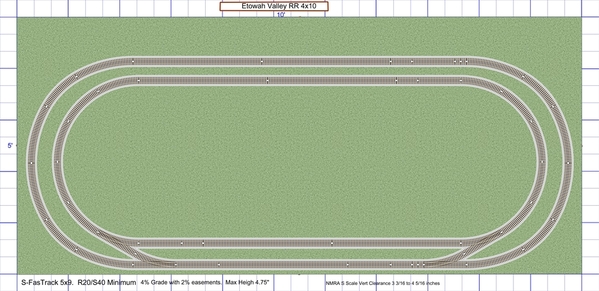
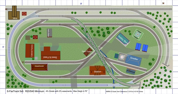
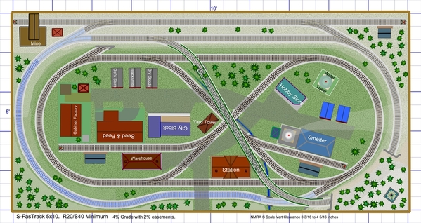
I decided to extend my build, from a 5x9 to a 5x10.  I have the space and like the look - that is, the expansiveness of the smaller trains in the same space.  HO is just too small, but S still has some of the physical presence of O.   So I am going for this Phase 1 intermediate version.

S59_V4a-Phase01

The autoreverse unit came in yesterday.   Its bigger than I expected, with big heat radiation fins.   Will experiment with over the weekend.

Attachments

Images (1)
  • S59_V4a-Phase01
Last edited by Ken-Oscale

Latest Two S FasTrack R20 command turnouts:  The latest two turnouts work very well, no problems or hesitation on switching.   No problems with remote or command control.

These two both had two difficult-to-connect problems:

  • The previously mentioned issue of the bulb/receiver being too tight to physically connect (the pressure required actually deforms the plastic, which springs back to shape after pressure is removed).   I trimmed all the "bulbs" by scraping with the back of a knife blade, about 10 passes works on each side of each bulb, which does not take long.
  • A new problem with both of these turnouts, on both of the diverging legs of the turnouts, one track end is slightly bent/mis-aligned.  One can visually see the curvature error, though it is small.   But, this causes the rail to hit the outside of the rail joiner on the connecting piece, and prevents a connection.   I tried many ways to get the joiner to enclose the opposing rail - no joy.   So as a last resort, I used a tool to bend out the joiner a bit, and also to widen-out the joiner.   This works, no problems with electrical conductivity so far.   The error is small, and my S trains do not notice it.
  • I also tried to gently bend the rail back into shape.  My first attempt popped the rail out of the molded plastic spikes (fortunately, it went back in this time).  This is delicate track, not at all tough like O FasTrack.
Last edited by Ken-Oscale

Here is a pic of the auto reverse unit.  Larger than expected, with large heat radiators.  I will work on testing it this weekend.  Reading the manual, this is a very impressive piece of electronics, with many capabilities and much flexibility, more than I will use - a very well thought-out design.

IMG_0603

A nice view of the train.

IMG_0604

Attachments

Images (2)
  • IMG_0604
  • IMG_0603
Last edited by Ken-Oscale

Experiment for more interest in the grade, to break-up the many parallel lines.  Not sure if I like it or not.  Its all R27 (==O72) to reduce the added drag on a train climbing the grade with curves (except one R20 (==O54) near the top, the turnouts are R20).

S510_V4c

I hope there is enough commercial interest that Lionel invests more in this track system.   1/4-section of S27 would be great in making graceful curves.   And add a #4 command switch (LH&RH).   And R24 (S48) curves would be great as well.  And fix some of the production problems I am encountering.

Attachments

Images (1)
  • S510_V4c
Last edited by Ken-Oscale

Ken, I have five of those PSX-AR-AC's. The heat sink is needed because these are rated at 10A continuous. I recommend not devoting too many brain cells to that manual. 90+% of the features described are not included in the AC version. Obviously any feature or setting that uses a CV value is not included.

I think we can forget about numbered S gauge turnouts from Lionel. As a minimum numbered turnouts would need custom curve segments to allow "closing a circle" with sectional track.

SHS made 19", 24" 29" radius curves. These work well with the 5" curve spacing, no engines or cars hit on curves. Lionel has 19" and 27" so they would need to make a 23" to have 4" spacing on the curves. I agree Lionel needs to ship customers turnouts that work first time, every time.

If you want to eliminate the appearance of parallel track, maybe rotate the entire lower level oval and "X" crossing 15 degrees clockwise on the layout. 22.5 degrees would be better but I do not think there is enough room to do that.

@AmFlyer posted:

Ken, I have five of those PSX-AR-AC's. The heat sink is needed because these are rated at 10A continuous. I recommend not devoting too many brain cells to that manual. 90+% of the features described are not included in the AC version. Obviously any feature or setting that uses a CV value is not included.

I think we can forget about numbered S gauge turnouts from Lionel. As a minimum numbered turnouts would need custom curve segments to allow "closing a circle" with sectional track.

SHS made 19", 24" 29" radius curves. These work well with the 5" curve spacing, no engines or cars hit on curves. Lionel has 19" and 27" so they would need to make a 23" to have 4" spacing on the curves. I agree Lionel needs to ship customers turnouts that work first time, every time.

If you want to eliminate the appearance of parallel track, maybe rotate the entire lower level oval and "X" crossing 15 degrees clockwise on the layout. 22.5 degrees would be better but I do not think there is enough room to do that.

Lionel and other manufactures package turnouts with small sections:  Lionel O FasTrack O36 with an O36 1/4 section.  Lionel O FasTrack O60 and O72 turnouts with 1-3/8" sections with roadbed trimmed, just for use with turnouts.   I think the low volume of sales is what discourages Lionel from attempting this, in S or O - doesn't justify the development and tooling costs.

As you observe, there is not enough space to rotate the entire layout, without making major changes.   So, I am looking at what is feasible with this plan.

I am finding that the S FasTrack 30" straights can only be ordered in a bundle of 10.   So I ordered 10 yesterday.  Particularly with the extended layout to 4x10, I need more straight lengths than previously, and will replace 10" straights in groups of 3, to be reused in different areas.

Two activities to do now:  test the PSX-AR-AC, and purchase and cut a 2" 4x8 sheet of foam, to add 1' of width to make the 5x10.

Train and turnouts continue to run well, with no issues.

Last edited by Ken-Oscale

I tested the turnout indication LED idea:  Works fine, very easy with the "conditioned" LEDs from Evan's Design for up to 19v AC.  I wired one green and one red LED from the frog to an outside rail and tested.

Unfortunately, the make/break of the internal turnout wiring to the frog/gate and points does not have a dead spot in the movement.  Turning the turnout stand manually, the electrical connection (and my indicators) go from one setting to the other, even when the points and gate are not fully one side or the other.   That is to say, the LEDs indicate the direction correctly when the turnout is correctly switched, but will show incorrectly when the turnout is "stuck" midway through:  a "false positive" situation.   So the LEDs will correctly show the position of the turnout when completely thrown, but will not show a stuck turnout.   (no turnouts are sticking at present).   Too bad.

I will still use the LEDs to bring out the setting of the hidden turnouts, showing in a block signal at the tunnel entrance, so I can see how the turnouts are set without being able to see the hidden turnouts.   That much works fine.

I will remove the turnout remote controllers soon, no longer needed with command control.

Last edited by Ken-Oscale
@Ken-Oscale posted:

I tested the turnout indication LED idea:  Works fine, very easy with the "conditioned" LEDs from Evan's Design for up to 19v AC.  I wired one green and one red LED from the frog to an outside rail and tested.

Unfortunately, the make/break of the internal turnout wiring to the frog/gate and points does not have a dead spot in the movement.  Turning the turnout stand manually, the electrical connection (and my indicators) go from one setting to the other, even when the points and gate are not fully one side or the other.   That is to say, the LEDs indicate the direction correctly when the turnout is correctly switched, but will show incorrectly when the turnout is "stuck" midway through:  a "false positive" situation.   So the LEDs will correctly show the position of the turnout when completely thrown, but will not show a stuck turnout.   (no turnouts are sticking at present).   Too bad.

I will still use the LEDs to bring out the setting of the hidden turnouts, showing in a block signal at the tunnel entrance, so I can see how the turnouts are set without being able to see the hidden turnouts.   That much works fine.

I will remove the turnout remote controllers soon, no longer needed with command control.

That's what I was getting at in my previous comment. If you want positive indication, you'll have to devise something mechanical.

Brendan

Experimenting with the Legacy controller to switch command routes.  It would seem from my experiments, that more turnouts in a route increased the probability that a turnout will not switch.  This maybe implies a voltage drop issue with say four switch machines all trying to switch at the same time.  I may do some experiments with this idea.  Currently, I am powering the layout with two CW-80s ganged together, putting out maximum voltage, with the engine running while I hit the route.  The turnouts take power from the track.

I also notice that if the route button is held down, the controller will send a command repeatedly in successive pulses.   I have even seen a route behave this way, with the button held the entire time: pulse-1: switch one fires, the others buzz.  Pulse-2, another switch fires, the others buzz, etc until all four turnouts have switched, and the button is released.

Sending a command to an individual turnout: they are all switching reliably as individuals.

The open circuit voltage output of the CW-80 is 17.9v.  

Last edited by Ken-Oscale
@JFC454 posted:

You might try increasing the switch delay in the "Route Throw Rate" on the Cab2.  I seem to remember that things worked better when there was a substantial delay.  Then one push of the button would sequentially throw the switches with a delay between each of them.  

That sounds like a great idea!  Unfortunately, I have the Cab1L, I think that feature is only available on Cab2.

My Berkshire threw a shoe!   I lost a traction tire after less than two weeks of operation.   It deteriorated and left black bits on the drivers and rails, and stretched out.  I was able to clean the loco up, and re-seat the traction tire, but it came off again while running.   So I cut it off, and will replace it eventually.  For now it is running fine with just one traction tire.

Last edited by Ken-Oscale

Add Reply

Post
The Track Planning and Layout Design Forum is sponsored by

AN OGR FORUM CHARTER SPONSOR

OGR Publishing, Inc., 1310 Eastside Centre Ct, Suite 6, Mountain Home, AR 72653
800-980-OGRR (6477)
www.ogaugerr.com

×
×
×
×
Link copied to your clipboard.
×
×