Darn, and they're some terrific pictures. Here's one... lets see if it shows up.


|
|
Darn, and they're some terrific pictures. Here's one... lets see if it shows up.

I saw that last picture but not the earlier ones.
I agree with Pat! Also I agree the last post shows they are great photos!!
Trainman,
I'm always following your progress and thoroughly enjoy every post.
Just love that you permit us to share in your thought process as you encounter challenges.
Your progress should be an inspiration to those that want to get their fingers dirty by stopping dreaming and starting to build.
Half the fun is figuring it out.
Ron H
Same as Pat & Mark with the pictures here. This happened to me a time (or maybe two) with pictures (I could see them but no one else could) and I think I just reloaded them, but I can't remember exactly what happened?
First I'll repost all those pics from last night. Then I give today's update. We'll see what happens today.


Now onto today's tasks. I permanently fastened the new tunnel portal into the layout. And I mean PERMANENTLY! Before doing this I needed to prepare the outlet more. I draped Hydrocal-soaked strips of Bounty to fill the gap between the portal's legs. I used four layers of towels since this was stabilizing the lower piece of fascia as well as place for the "waterfall". Then I slathered STM liberally on the portal's backside after wetting it, and pushed it tight into the opening. I smoothed the inner junctions with a wetted finger (I always wear nitrile gloves when working with plaster). I then added additional STM to the bottom of the two legs and some in the middle region. For the leg extensions, I hand carved some stones to make it look like the portal's longer than it (after painting of course), and carving some strata rock in the middle where a faux waterfall with appear to be dumping water on the floor.


We're almost ready for the resin. Tomorrow this new plaster will be dried enough for painting. That will need dry time also. I also have to add the silicone water falls. I'll use the same material to adhere them to the rocks and that too will require a good amount of dry time. So... based on that, resin pouring will probably happen on Tuesday. And oh... I almost forgot, I do have to add the long grass before resin so that too will happen tomorrow. I'm pleased with how this whole deal came together. I really wasn't sure how building that window screen tube off the layout and then getting it into place and sealed tight would work. But it did.
And one more thing. Just got a note from the Editor of Railroad Model Craftsman. The Distillery article goes in next month and will be in two parts due to its length. I hadn't heard anything and was thinking it wouldn't happen, but it is.


So... didya see the pictures?
Yes they show, it's this composer. Likely updates are coming.
I see lots of great photos! I wasn't sure how you were going going to run the culvert under the track! As it turned out I wasn't imagining that you would go so low on the facia. It looks great! Once painted and 'water' solidified, it will be very convincing
Yes, much better on the pictures, looks like they are all showing here now, yesterday's and today's.
Thanks, Miles, for reposting the pictures. They look good. Congratulations on the RMC Article. I followed along while you built the Distillery. It makes a great article.
Congratulations on the RMC article! I will have to get a copy of both issues!!
Great news on the article. I bet they will want to do one on your mountain and ponds with the waterfall.
Also a congratulations on the RMC article. I will be watching my LHS for a copy of both issues.
Thank you all! I'm not sure that doing the mountain is newsworthy since there are many fellows out there who do terrain work and there's lots of videos on it. That being said, most of them aren't this huge, nor are they almost entirely built of cardboard. I sent the Editor some other project pics that could become future articles. One of them I'm working on now on SketchUp. It's my rendition of a Rick House under construction. I would limit it to just the first story and a bit of the 2nd since it would consume a ton of Kepler scale lumber. It scales out to 40 X 64 feet (10" X 16"). That compares to the huge real ones that Heaven Hill is building. Those are 125 X 300 ft. They're 7 stories high so it's 263,000 sq. ft per house and they're building 8 of them. That's over 2 million sq. ft of warehouse just to age Bourbon and they have 40 others around the state.

Even though you can't see in this image, all the lumber is the same size that's used in the real one. I'm also modeling angle plates were they can be easily seen.
Today, I finished up portal and glued in the waterfall pieces using clear silicone caulk. I also started to "plant" some saw grass around the pond.
Here's the completed portal, painted, tinted and ready to go.

You cut the Saran to remove the water falls. You don't attempt to peel them off the Saran. To cut the top part I taped it to the cutting board so I could pull it taut which made using the scissors easier.

Here's the waterfalls attached to their respective places. They will look better when infused with tinted resin... supposedly.
Main Falls

Mid Falls

Outlet Falls

Upper Falls

Last thing I did today was start putting in some vegetation. This is W-S tall grass. I'm using W-S Scenic Cement (the thick stuff). I was having trouble keeping them sticking up straight so I'm adding a drop of medium CA to give it more oomph. I didn't finish this today so I'll have to do it on Monday. I may put the resin on the falls first since that will be ready. The pond will wait until the grasses all dry.

Monday and Tuesday will be big days with the completion of the mountain range and water features.
Have a nice weekend and keep warm. It will be the first week that football players heads will be steaming.


I think all the water falls will look great when completed. The culvert, painted and shiny with water looks very good! Very nice method.
I really need to ask this as nobody has spoke of it in the many years I've been reading here, and I think a few different folks are using the term for both types of glues.
Does CA mean cyanoacrylic or an old fashioned contact adhesive?
Thanks!
When I use "CA" I mean cyanoacrylate. When I use "STM" I m referring to Sculptamold. When I use "PSA" I mean Pressure Sensitive Adhesive which is a specific product of MicroMark. I rarely use Walther's Goo since it seems more trouble than it's worth and doesn't hold forever. The other acronym I use is "RSU" which is my American Beauty Resistance Soldering Unit. Otherwise, I will spell stuff out.
Adriatic posted:I really need to ask this as nobody has spoke of it in the many years I've been reading here, and I think a few different folks are using the term for both types of glues.
Does CA mean cyanoacrylic or an old fashioned contact adhesive?
Are we all showing our age here knowing what an old fashioned contact adhesive is? ![]()
Thank you Myles for the descriptions. I was thinking cyanoacrylic, but Adriatic, your was a good question.
Remember the old Ambroid "airplane glue' that turned yellow on the places you didn't want it as a kid building models.
Ambroid and Duco Cement made balsa model building a horror. It wasn't until CA came along that working with wooden modeling was actually was fun. You can build and RC wing as fast as you can go. You don't even need to clamp. You hold the rib, put on the CA, squirt it with accelerator and then move on to the next one (as long as you haven't glued your fingers to the model). I've been a regular user of CA since the 1980s when they first came out in retail.
A bit of history. We can thank Eastman Kodak for CA. (Eastman 570 I think) They developed it for gluing lenses together. Industry picked it up for various odd uses. For example, you could glue thin metal sections to a plate so you could surface grind it (if it wasn't magnetic). Acetone would then break the bond.
Another interesting fact. Henkel is one of the world leaders in making CA. The plant is in Ireland. How do you produce a liquid that binds up metal parts? You run the machinery at a temperature below freezing. When that cold, CA does not cure. If you want to keep it fresh, put it in the freezer.
Cyanoacrylate is also used in theatres of war for quickly suturing lacerations together.
I've used it in my modelling room when I've been too enthusiastic with a blade. ![]()
And it doesn't sting. ![]()
Good tip on the freezer. Every time I try to use my CA is usually dried up. Although, I have had some Gorilla CA for 2-3 years now and it was still working as of a few weeks ago. I have never had any last that long before.
I had heard of CA being used for cuts, but never tried it. Another good tip. I am usually better at gluing my fingers together than much of anything else, so I definitely know it works well on skin. ![]()
They're using tissue glue in a lot more applications than just battlefield. I believe it's got a different chemical basis so it's not quite so aggressive. Stevie Ray Vaughn used to play until his fingers bled. He then coated them with super-glue and went back and played some more. Now that's dedication. When my fingers start to bleed, I stop playing. Actually, I stop playing a long time before that.
Did some rare Saturday work so I almost finished getting the saw grass planted. I'm leaving a blank spot so I can install a little fishing pier. It's just a pond so a boat is not in order, but a fishing pier could be okay. I'll build that on Monday. The super glue I was using yesterday dried frosty so I didn't use it today, just got more patient with the W-S Scenic Glue. I had to be careful and stop breathing since sometimes I would blow over those delicate little placements.


rtr12 posted:Good tip on the freezer. Every time I try to use my CA is usually dried up. Although, I have had some Gorilla CA for 2-3 years now and it was still working as of a few weeks ago. I have never had any last that long before.
I had heard of CA being used for cuts, but never tried it. Another good tip. I am usually better at gluing my fingers together than much of anything else, so I definitely know it works well on skin.
I agree on the tip on the freezer, and also on gluing my fingers together. ![]()
Reminds me of a guy I worked with over 20 years ago now. He liked building model airplanes. He was an excellent story teller, and never minded telling a story where he was the brunt of the laugh either. One day he told us that he had been using fast dry CA when he got a little too ambitious and some squirted into his eye. Of course he blinked. All of a sudden his eye was glued shut!! He got his wife to drive him to the emergency room, and she laughed at him the whole way there and while at the hospital as well.
I was going to add about, "Don't let it get in your eyes." A long time ago, I was using a pinpoint to apply it and the point sprang and small amount went into my my eye. It didn't hit the cornea and burned a bit, but I got it under water right away and it was okay. My son, the ophthalmologist does see this from time to time. I don't have too much trouble gluing fingers together and I have the acetone handy nearby.
I haven't done that yet, and hadn't really thought about that one either. I will watch out for my eyes! I got my cataracts fixed last year and I only need glasses for close up so I don't always wear them unless I really need to see something close up or read the fine print. I will be wearing them more often when working on things, especially when using CA or other glues.
Back to the topic. I got all the grass done and started building a little fishing pier that will jut out into the pond. I'm also thinking about ways of crafting some miniature cattails. I know that Scenic Express has them, but I wanted to have them before doing the resin work.
Putting on that W-S long grass is finicky work, but the results are pretty nice. It's a finer fiber than using sisal rope fibers, but those might work well for the cattails. Like everything else on this layout, I finally got good at it when I was near the end.

I drew the platform up SketchUp yesterday to see how I wanted to build it.

I kind of slapped it together out of various styrene strips. The frame is s strips plus 6, 3/16" sq. legs. It's just sitting there. To install I'll probably inset it into holes in the scenery.

To hold the planks in position for gluing, I spaced them onto some reversed masking tap and then turned the frame upside down with some weight on it, and applied solvent cement with the Touch-n-Flow applicator. I didn't spend too much time getting it perfect since this is supposed to be a very crude little platform.

Here's the assembled platform again sitting by the "water".

I used my scratch brush to rough up the styrene's surface to make it more "wood" like. I would have liked to have used real strip wood for this, but didn't have any and didn't have a good local source for it. Again, I didn't want to wait for on-line delivery. I attempt to do a faux wood paint job on it. This is now right in the critical path of getting the resin poured since all the other water features are fully cured and ready to go. I suspect that I'll sink the platform another 1/8" to 3/16" to bring it closer to the water.


I finished and installed the fishing dock today and then got the first layer of polyester bar-top coating.
To color it so it looks like aged wood, I first covered it with Tamiya Surface Primer. I'm really learning to like this stuff since it covers great and dries fast. It's also not alcohol based so successive coats of Tamiya color coats don't dissolve it. I then used a thinned Tamiya Dark Iron brown. This was after I had scratched the surface to give it some "wood grain". I left two planks unpainted which I then painted with some wood tan to show a couple of recently fixed planks. I painted on some simulated knots, but I realize now that I didn't make a nail holes. I can go back and do that if I want. I'm not sure I want to.

I trimmed the back two legs so it fit over the land area, shorted the other four legs a bit since it was sitting pretty high and then glued it down to the base with some W-S Scenic Glue. To hold it down till it dried, I added some handy weight.

When this set up I mixed the polyester. It's a "equal Part A/equal Part B" affair, plus I added three drops of Tamiya Olive Drab to give the water a bit of green tint. I poured the first amount in the center, but it didn't appear to be enough to cover the area. So I mixed up another small batch and poured it around the edges. It all blends together and flows like lava, eventually getting into all the spaces. I used a hot air gun to try and drive out the bubbles, but wasn't completely successful in this.

Here's the full pour in place and setting up.

The water is not dead flat! The plaster bottom is a bit high in the center. Tomorrow, when this sets up, I will make another pour and get it all leveled out. I didn't do a good enough job of cleaning the surface before pouring since some of the "Bubble" may actually be particles of ground cover, etc.


Today was a milestone... of sorts since I was able to get "water" into the stream bed. There's still more to do.
I first took some fine emery stick and wet-sanded the pond surface to get rid of the bubbles and dust that was there since I hadn't cleaned the surface well enough. I then mixed another batch of the Park's product and added a new layer. It almost eliminated the high spot, and caused resin to extend well beyond the saw grass in a couple of spots. I'm going to re-landscape those spots after all is cured hard. There's still a bit of distortion where that high spot is. I may or may not go with one more coat to finally level it off. My grandson noted that high spot and I felt that the resin would have buried it long before now. I did get out all the bubbles and there's no more dirt in the pour.

I then mixed up a batch using some very old Envirotex from about the late 1980s. It will find out if it still cures. The two liquids looked the same as the Park's material so I'm optimistic. I just checked and it is curing.
To do the stream run I first brushed resin into the waterfalls and wetted the stream bed. The resin has a very high surface tension so it helps to pre-wet flow areas. I added the Tamiya O.D. paint to tint the water a bit of algae green. I may have overdid this effect a bit since as a mountain stream it probably would have been completely clear... oh well.

I didn't wait for this to set up, but immediately went ahead and mixed more and poured it from the top and let gravity do its work. It move like molasses or maybe like thick lava. It doesn't stop, but just creeps along.

I didn't like how the flow was not going over that rock in the upper mid-stream and decided that having a waterfall off that rock was completely unrealistic. The water wasn't going up and over that rock so there wouldn't be a falls there. I removed it. I added some more downstream to get it moving along.

As more material filled the void, I found some low spots that I thought were no longer there. I plugged these with some modeling clay to stanch the flow and will landscape the area after the resin cures.


Then the material started getting to the lower reservoirs, but I also added more there too.

And after adding even more resin, it finally found its way out of the outlet. I put a cup on the floor below to catch the drips as they worked their way out of the system.

After all this cures, I have more work to do. I have to highlight the falls with white paint mixed with W-S water effects and make some white water foam using the above and some CA filler beads. I will also add stream lines and more turbulence with more water effects. By this time next week, the stream should be done and I'll clean up the landscaping and the floor (again!).


Yes I recall using a similar product years ago, it gave pretty good results. I did have one little seep hole as I recall. Yours is on its way to looking great! The green tint probably won't be too noticeable. I was going to say the last falls looks like it could go to the floor, and so it did. Looking good at this stage.
I have not had a chance to watch the progress for a little while
It is great and serves as a wonderful motivational thread
Thank you
Bought some more Enviro-tex resin today. The 25 year-old stuff was Ultra-glo and it still worked great. It was cured solid this afternoon. I added the water effects which included three different concoctions: plain W-S Water Effects, Water Effects plus some Vallejo white acrylic paint, and then these two plus some micro-balloons filling agent to bulk it up. The plain Water Effects was used to give flow lines around the various obstacles. The white/Water Effects mix was used to add white to the turbulent areas and to the falls themselves, and the bulked up stuff used to create 3D foam at strategic locations. In the first instance, I wish I would have made that falls extend from the top to the bottom. I think it's too late to make that change.

This should be so white when it all cures. We'll see. I also built a little dam with Water Effects in case I want to make another pour of the resin to fill the reservoir more completely.

I'm also not too happy about the flow lines from the final rock in the flow. You really shouldn't brush the stuff on since it doesn't give the wavy feel that water would do. It gives the tops, but can't resolve the troughs. You can see in the following pic the areas that I added more plaster to fill the divots left behind by the modeling clay dams.

This plaster was a combination of Gypsolite and Hydrocal. I did this to hopefully accelerate the setting time. We'll see. I used this mixture to also revise the banks of the pond so I can re-pour the resin to finally flatten out that high spot without extending the "wet grass" even further.

For this next pour I'll probably leave it clear since there's already enough green in the water. Any more algae there and I'd have to put in an aerator.
Tomorrow, I'll take another look at all of it and see if there's anything else I can do. If not, I'll paint the bare areas of the foreground and add ground cover, thus finishing up this part of the project. I'm going to add more color to the area where the mine's going since I don't know when I'm going to build that and don't want to look at bare plaster.


I really love how its turning out! Just a thought about the top water fall, couldn't you just make another section like the one you have there just longer. Then attach it behind the first one.
I think when everything is said and done its going to be just GREAT!
That's a possibility. One problem is that making long strands of falls requires a different technique than the ones I made. Kathy Millatt uses silicone adhesive strands for the long falls instead of a glob stretched out from the caulking gun with the silicone caulk. You can also use W-S Water Effects to create falls. I would use a small nozzle to emit some smaller strands. I can also remove the current falls to replace it, but it won't be easy. It's well fastened in place. I think this whole deal's going to grow on me. Also, unless you're inside the middle of the layout, You won't see much of those effects.
And I'm really glad you feel that way.
Well... the mountain's as done as it's going to get. I still have to put in trees, bushes, etc., but it can hold its own now.
Yesterday, I added the last bit of Envirotex on the deep pond and figured a way to get a little more motion in the stream itself by adding setting resin that held a shape (sort of) so it made a more animated and more interesting to look at. This cured hard and today, I went back and put ground cover all all the bare areas, redid the ballasting where it was damaged, ground-covered that little back section on the elevated track—which required me to come up in the open space I left in that rear section—and painted those last bits of rock along the stream bed and where the mine's going to be. Here's a set of pics I took tonight after putting everything away and sweeping the floor.


Here's a few other views. I do think I'm going to try to write an article on this build.


On the weekend I worked re-drawing the Night Hawks cafe that I'm going to build for the town. I've spoken about this a couple of years ago, and I bringing it up again since I lost most of the building in SketchUp since I really didn't know what I was doing. I've since learned an important point about SketchUp (SU). Unlike Illustrator, Corel Draw or other typical 2D drawing program where you actually draw on different layers to separate parts of the drawings and determine what part of the image lies over what, in SU you do all of the drawing on Layer 0. Layer 0 contains all the math and calculations necessary to create a 3D image. Then.... after you've drawn whatever you're going to draw and you want to be able to show it or hide it as you're working, you then put it onto it's own layer. But, you never ever do any work on that object on any other layer than Layer 0. So I re-drew the entire project with this new-found learning and got a very stable project.
To refresh your memories, this building was a set of plans for a corner Victoria bar that was in a mid-50s Model Railroader magazine. I always wanted to build it even as a kid when my uncle gave he all his MRR mags. It has a mansard roof, gables and a neat turret. But I wanted to change it to try and duplicate Edward Hopper's American Masterpiece, "Night Hawks" which resides in the Art Institute of Chicago. It's one of my favorite paintings and he's one of my favorite artists.

While the drawing was created in SU, the renderings you see here are created in Podium, a SU add-in that not only does photo-realistic rendering of SU drawings, but has an extensive library of its own of 3D ready objects and textures. The chrome on the coffee urns was generated in SU and if you could get close enough, you'd see the whole room reflected in those appliances. Also see the reflections generated on the window glass, also a Podium texture.

Hopper's painting warped perspective. While the street corner appears normal, the inside of the building is sort of triangular so he could visualize the couple sitting over their coffee. Those folks are supposedly Hopper and his wife, and I'll have to sculpt the people myself. The room appeared to lit by then-new florescent lights so blue white LEDs will work well. I have created the missing art work for the signage and will make my own decals for it. The building in the painting looks like one floor which is strange since the street appears to have typical city brick store fronts.

This building will queue up behind the 2nd distillery for Heaven Hill, the Plastruct chemical plant, the engine house, and the under-construction Rick house. In other words, G_d willing I'll be building it in 2017 sometime. The nice thing about SU is I can do all the design and engineering work on a building before buying or cutting anything. If it can't fit together in SU, it ain't gonna get together in the shop either.
While waiting for River Leaf to cut the 2nd Bernheim distillery, I'm going to start planting some bushes and layout the parts for the chemical plant to decide on where it will go on the layout.


Fantastic job Myles. ![]() The mountain and it's scenic details looks great. I like the way the stream and pond came out. I can't wait to follow your effort on the Night Hawks Cafe.
The mountain and it's scenic details looks great. I like the way the stream and pond came out. I can't wait to follow your effort on the Night Hawks Cafe.
Myles:
I've enjoyed following your thread and look forward to all your future projects. This is both entertaining as well as instructional. Thanks for the taking the time to write this.
Robert
Congratulations on the mountain, streak, and pond scene!! There will make it even better. I look forward to seeing the Nighthawks building. I first became aware of the painting long ago as I read John Armstrong's article of his Nighthawks building. Then I got to see it on his layout almost 30 years ago.
Thanks everyone!
It was Armstrong's model that inspired me. I saw pictures of it on John Scaice's layout who bought all of Armstrong's stuff. I have the coffee urns which are resin castings from Westport Model Works. Now all I have to do is build a cafe around them. Easy Peasy!
Remember dear readers, there's a lot of stuff to be built before Nighthawks so be patient.
Waiting is quite alright! Rome wasn't built in a day
Don't look now, but this railroad is going to take almost as long as it took to build Rome, or at least a Gothic Cathedral. We built two new suspension bridges in Louisville in a lot less time.
Myles,
The mountain looks great! Don't forget when you start adding the trees and bushes, we also have tree stumps that you can mix into the scene. Attached are a couple pictures and link if interested.
http://www.scalecitydesigns.co...e+stumps&search=


Good looking stumps!
With the mountain completion it's time for a comparison shot showing what happens with almost four years of effort. This was literally four years ago on December 24, 2012. I was assembling all the track in preparation to trace its outline on the OSB in order to properly glue down the Flexibed.

And here is is on December 22, 2016. I'd hate to think how much more I would have had to do if I wasn't working on it almost every week day being retired.

There's still a lot to do, but the big, heavy lifting is done...whew! Just in time too since I'm not getting any younger. The chemical plant will go along the back and the rick house will go on the bare 'land' behind the fire house. The engine house is designed and will also be built in 2017. That leaves Night Hawks Cafe in the place where the empty corner store is sitting on main street. I have open land in the back on the swing door. I'm thinking of some woodlands with a cabin in it. In front of the the cabin, sitting under a tree, will be a guy with a guitar "Strumming to the rhythm that the drivers made." The name on the door will be Johnnie B. Goode. That leaves some more yard buildings and things to fill the green space in front of the town. I may have a park in the front so the buildings won't hide the sight lines and then some buildings on the side. Then I have to put in the telephone poles, street signs, parking meters, some crossing gates, signals, etc, etc. As the famous Willie Wonka said, "So little to do and so much time... no, no the other way around".


Wow! Didn't realize I've been following your build so long! Thanks for the memories!
Time flies when you're having fun. I find it inconceivable that so much time has elapsed ("you keep using that word. I not sure it means what you think it means" - The Spaniard, Princess Bride),
I explained something to my wife the other day; I was trying to help her understand just what drives my obsession with building the layout. What she can't realize is when I was building my 13 X 4' O'gauge railroad when I was 13 in 1958, in my mind I was building what I now have. In other words, I am realizing a dream I've had for most of my life and was unable to realize until I was old enough, had enough discretionary income, and the time to make it happen. I would pour over my 1950s Model Railroading magazines and Lionel catalogs and imagine having that in my basement. It took another 42 years for it to start materializing. But it wasn't until we moved to Louisville, in this house with its basement and being fully retired that this model railroad had a chance of being created.
Our daughter treated my wife and I to a holiday lunch at one of Louisville's many up-and-coming restaurants, Butchertown Grocery, so we didn't get home until after three and I didn't get too much work time, but what time I had I made good use of it.
I first had to vertically realign the inner loop track on the gate's hinge side where it meets the new switch on the fixed platform. I woke thinking of all the ways to do this since the gate track needed to rise about a 1/16". I was thinking about relieving the risers underneath to jack the gate side's sub-roadbed OSB a bit, but worried that this might be harder than usual since it's now locked in place with more structure and plaster. I thought about lowering the fixed side using the same method, but again, all that plaster would make it difficult. Then I chose "Achem's Razor" The simplest solution was to use a putty knife to open a space between the Flexibed and the OSB and slip in two piece of cardboard that raised the track the correct amount. Didn't even need any glue. Problem solved. After I did this I decided to run the trains and make a movie.
https://www.youtube.com/watch?v=sEL3T_16G18
I also wanted to finally get my favorite steam engine of all time running, my 3rd Rail Pennsy T-1 Demonstrator which was having some troubles. First I installed a new BCR to replace the now-discharged battery. I put it on the outer loop and it kept derailing as it crossed that same gate junction as I had just fixed on the inner loop. At first I thought the lead truck was too light and wasn't tracking properly so I stuck a self-adhesive 1/2 oz. weight on its bottom. This didn't work completely. It took the truck off the engine to see if the attachment bar was bent since it seemed to be tilted, but it was okay. Then I noticed that this track was also just a little bit high, about 1/2 the amount of the inner loop, so I didn't waste a moment, got the putty knife and inserted just one piece of cardboard. The truck then tracked perfectly, which led to the final problem. The tender was uncoupling from the baggage car as it was leaving the far portal. The coupler alignment was a bit off, but not easy to fix. What solved this problem was a couple of strategically placed orthodontic rubber bands (left over from my kid's braces). As you'll see in the movie, this engine now ran great and is back in the stable after a long stint as a shelf queen. I'll just have to remember to remove the bands when I want to couple up the Santa Fe F-3s.

So this is the last post until after New Years (unless I answer posts on the iPhone) so here's wishing all y'all a Merry Christmas; Happy Hanukkah; and happy, healthy, safe and wonderful New Year.
The video is great! As I said elsewhere, it is great to inaugurate the tunnels with the El Capitan and the Allegheny!!
Merry Christmas and Happy Hanukkah too!!
It's no secret that I am among the many modelers that have been and continue to be inspired by your dedication to follow through on your layout and your creativity. Always enjoy checking out your current work. Congrats.
I was just thinking a couple days ago, that Trainman said he wouldn't be back until after New Years! I thought he would check in before this though.
I hope you are okay, Myles!
I'm am fine...thank you for asking. And I'm glad that I'm still inspiring. That makes me feel very good.
I sent updated drawings to Andre at River Leaf to cut the Bernheim Distillery for Heaven Hill's Evan Williams Bourbon Experience. After conversations with Andre, we decided to go with 1/4" MDF instead of the 3/16" Masonite. This required lots of changes, wall lengths, floors, roofs, trusses. I'm going to do that project next since Heaven Hill has already paid for the cutting. Meanwhile, I'm working on the TBM Avenger model which is a nice filler in the interim. Here's a taste... it's not trains, but it's still models.
I made an open access panel to show off the details in the firewall area which would be hidden when the model was finished based on the instruction.

The seat belts are photo etched included with the kit.


Glad to hear from you and you were in touch with Andre on the new plans.
the Avenger looks great! I was just reading about George H W Bush flying a TBF Avenger. Is the TBM Avenger much different ?
??? Don't look at me for answers, I built more ships, & tanks ![]()
Some hot rods survived my teens, but all else was destroyed in firecracker battles over the years. Later I built a few more military models, but mostly hot rods and VWs. My trains are more of a haphazard collection with some modeling thrown in when the mood strikes me. Here is my last plane. Built to keep the monkey busy...and to keep Kong busy too. It sees layout time, so does Kong, and thats my Gramps jumping out of a perfectly good airplane...Cur Rah Heeeeeeeeeee... loved trains too...

On cars I'd add wires, fuel & brake lines, paint the speedo, locks, etc. The detail takes up a whole lot of time, and some gets buried, never to be seen again, lol. I've got about a dozen in a showcase, but it's buried right now.
One of my borders models cars. I got him hooked into weathering after he watched me dunking RR things in washes and smearing and spattering paint around on foam.
He is really into rust textures now. The 70s FORD is his first attempt, complete with rotted cab mounts. Look close at the fender tops of the rat truck below for rust & flake texture. It's everywhere. He frequents a couple of modeling sites and shows me the better RR efforts there all the time.
My pulp paper tunnel, left unfocused, is his favorite photo background.
My last models two were for the layout. Simple models done simply though. No brake lines.....
This is bleached with Photoshop to replicate one of my old ones pretty closely. It had such good paint that I left it yellow in the long run, and just detailed little things to match the white one. (The yellow one I had was slow & junky, lol. The white one ate horse meat. (beat mustangs)

It used to really frustrate me that models were mostly 1:24 or 1:72 and were not made in 1:48 when they were made an in between size.
I should dig at the showcase.


Great Pictures!! Don't feel bad, I destroyed a few things also when I was younger! But then again didn't we all?
Trainman2001 posted:I'm am fine...thank you for asking. And I'm glad that I'm still inspiring. That makes me feel very good.
I sent updated drawings to Andre at River Leaf to cut the Bernheim Distillery for Heaven Hill's Evan Williams Bourbon Experience. After conversations with Andre, we decided to go with 1/4" MDF instead of the 3/16" Masonite. This required lots of changes, wall lengths, floors, roofs, trusses. I'm going to do that project next since Heaven Hill has already paid for the cutting. Meanwhile, I'm working on the TBM Avenger model which is a nice filler in the interim. Here's a taste... it's not trains, but it's still models.
I made an open access panel to show off the details in the firewall area which would be hidden when the model was finished based on the instruction.
The seat belts are photo etched included with the kit.
Thanks for share the TBF build. My father was a TBF-1 tail gunner on Guadalcanal. After the war, he returned home and ended up working for the Chesapeake & Ohio railroad.
TBF was built by Grumman and the TBM was contracted to GM Eastern Aircraft Plant to build. Only minor differences exist that only a model builder would notice. The biggest difference is the full shield between the rear engine area and the engine. On the TBF is just a small disc, whereas on the TBM has a fully-formed streamlined enclosure. In the picture it's that blue shield you see. That piece is not on the TBF. When the cowl is on along with the cowl flaps you won't see this piece. There are some other minor differences which are not as noticeable.
I was interrupted writing the post to Mark's question and missed the neat pics of the car models. I don't which is harder to achieve: really good rusty subjects or pristine high-gloss finishes.
As a kid I built a model a week for years (or so it seemed). When the shelves in my room got filled, the great culling would take place as planes went out the window in flames, blown up by firecrackers or just summarily dumped to make room for newer and cooler stuff. It's easy to get into that kind of routine.
When I look at sites such as Old Models.com I can't believe how many kits between 1956 and 1961 I built. My mom always knew what I was up to. And apparently inhaling all those glue fumes didn't do any permanent damage.... or did it?
I think you increased your creative outlook anyhow, lol.
That later non-toxic stuff never worked as well anyhow.
I think the kid shows promise anyhow. You know photos are harsh. He still needs to use less glue, but has made huge leaps in quality overall.
The rust scale was one of three kinds of salts, and/or baking soda. The flaked salt areas look best to me. There are various experiments seen on the brown truck.
Trainman2001 posted:TBF was built by Grumman and the TBM was contracted to GM Eastern Aircraft Plant to build. Only minor differences exist that only a model builder would notice. The biggest difference is the full shield between the rear engine area and the engine. On the TBF is just a small disc, whereas on the TBM has a fully-formed streamlined enclosure. In the picture it's that blue shield you see. That piece is not on the TBF. When the cowl is on along with the cowl flaps you won't see this piece. There are some other minor differences which are not as noticeable.
I don't follow airplanes much, but the name Avenger certainly caught my eye. Now I know they were made by two different companies and have minor differences. That adds to my knowledge base. Another coincidence happened when I read an account my uncle wrote about a relative who dictated his experiences on the carrier San Joaquin. Bush Senior was on a sister carrier, so our relative's account added information. Three separate information sources in two weeks about something I knew nothing about prior. Maybe I will remember some of it! ![]()
Just stick with me Mark. I am a fountain of miscellaneous and often useless information. If it has wheels, gears, engines, etc., I probably know something about it. Don't ask me about sports or legitimate theater, but just about everything else I know something. I am the living example of the pure "generalist". I know less and less about more and more until I know absolutely nothing about everything. That compares to the pure specialist who knows more and more about less and less until you know everything about nothing.
Ha ha! I love it!!!
Don't panic, it's mostly harmless, and not entirely unlike other situa_ions a towel could clean up fas_. I thought deep and on _hat and have only one relivan_ conclusion...42! (... and it's missing teas!)
(Google "42" and read wikipedia if you must, it's semi-obscure, but a fav.& not TOO bad as a movie either if the excessive paperwork bothers you. ![]() )
)
Funny!
Just checking in... working on the TBM waiting for Andre to finish cutting the next distillery. We're doing this one in 1/4" MDF instead of 3/16" Masonite. It's smooth on both sides so he's able to cut bricks on the backsides so I'll have engraved bricks on some of the exposed rear (or front) surfaces without having to use additional laser cut ply pieces. Less piece count means faster assembly. But... changing the wall thickness caused changes in floors, walls, roofs and trusses. In other words, almost everything. I also adjusted the window sizes so they'll be a tighter fit in the window openings reducing the need for backing pieces. Again, lowered parts count.
I checked the overall sizes of the Plastruct Chemical plant and it will go where I first thought, in the last open woodwork area on the front edge of the back portion of the layout. I may pipe the plant's in and out piping over the tracks so the car loading facility will be facing the viewer with the track between the refinery and loading facility. It will reduce the overall width needed by about 6".
This means that the Howard Grain Elevator (B.T.S.) will go between the tracks on the back of the layout.
Sent another article to RMC yesterday on building the mountain. The editor isn't sure if he'll use it since the structures articles are more interesting, but he's going to take a look at it. My publication date for the distillery article was to be next month, but it's being moved out one month and will be at least two issues due to length and number of images. If he rejects the mountain article I may offer to other publications.
Took another picture of the mountain looking across the layout using the photo stacking software to give very large depth-of-field.


Bought something today. The other day I saw a late-model MTH Santa-Fe Super-Dome car. I don't have any dome car in my Santa Fe consist so I've been using an older MTH Rock Island Golden Rocket Super-Dome. I don't think either of those railroads actually had super domes since I think the only one that did was the Great Northern. Santa Fe used the normal dome car made by Budd. However, that car is not available as a separate car. It's part of an MTH passenger set and I don't know who likes to break them up.
Anyway, this car was perfect! I believe it was unused, but didn't seem to have any box. The list price in MTH's catalog is $100. The sticker said $60. Not bad... I saw two other MTH Super-Domes in boxes with different road names. One was tagged $55, and the other $50. So I said, since this one is without a box and you have another for $50. I'll give you $50 for it. Deal!
I now have a fully stainless steel El Capitan. The Rock Island car will be sidelined.

This car has nice sprung, equalized trucks. Which is a later model changed for MTH. The door also opens. Is there a brake cylinder missing? Yes... there is since I see one of the right hand truck. I wonder if they're available from MTH as parts or do I have to machine one.

Here's the Rock Island Car.

The Rock's trucks are solid castings. I really like sprung truck.

This weekend is a "Great Train Show" in Louisville this weekend. I'm going. Whether it's with any grandsons is up for grabs since they're getting older and don't have much free time. However, a fellow I'm mentoring has a nice young son who is into trains and we've gone together last year. We're probably going again this year. It's not a big show and has a lot of non-O'gauge trains. But I like to go anyway.


That perfect car had a brake cylinder missing off one of the trucks. I went back to the train store and they're seeing what they could do about it. MTH lists the entire truck on their parts list, so they're going to see if they can get just the cylinder. If they have to buy an entire truck, I might split the difference with them.
Today, the new Bernheim Distillery laser cut parts arrived from River Leaf Models.

I had one piece that I had reversed and had the bricks engraved on the wrong side which Andre is going to re-cut for me. I can already tell that this "kit" is going to be much easier and faster to build. Several changes made this happen. I switched from 3/16" Masonite to 1/4" MDF. The Masonite is only smooth on one side and therefore, if any brick engraving is needed on the other side, it had to be added as engraved ply overlays. With the MDF, I drew and Andre cut bricks on both sides for areas around parapets and back side of the clerestory wall.
This image shows the reverse side engraving on the transverse wall saving having to glue engraved appliqués to create the illusion.

I adjusted the window frame cut size so I won't need a backing piece to hold them in. On the prototype, I drew the windows at the exact same size as the opening. But the laser beam has some width so the hole gets a few thou bigger, and the cut window a few thou smaller, so the end result is about .005 to .007 gap so the windows are loose.
Since, I documented the prototype build in great, gory detail, I will refrain from posting on this new build unless there's something of interest that is new. One will be painting and grouting all the engraved brick areas while they're unassembled and in the flat. It really facilitates removing the excess group with a razor blade when you don't have to scrap into inside corners and hold a very substantial building at odd angles. I also got the window lintels engraved into the body instead of adding them as separate parts. Many building's lintel brick work is not in relief. I am still doing the sills as a add ons.
I thought my article on this project would appear in this issue of Railroad Model Craftsman, but I found out that it was moved out one month due to its size. It will be at least 2 parts and maybe more. I submitted another article on building the boiler house, which is in the queue, and recently sent another on building the great cardboard mountain. They're not sure if they'll use it since they lean towards structures and more precision projects. If they can't use it, I may sent to OGRR and see if they'd like it. RCM is doing well under its new leadership. They have over 800 articles now in the queue.
Andre and I talked a bit more about making the distillery into a master-level kit. I'm about 1/2 through writing the instructions just in case we do offer it. Instructions will be very complete and transmitted as a PDF. included in the kit will be some cursory information. We haven't decided on price point or how we split any proceeds. You know...business stuff.
I'm finishing up the cutting drawings on the Night Hawks Cafe which will also be brick and laser cut. Again, if it builds nicely, it could also be a very interesting and fun kit. I have a refinery to build and an engine house as well. 2017 is just about booked out.
Great photo of the mountain overlooking the tracks and trains. Layouts are never really finished are they?
Your improvements on the 'kit' certainly sound great indeed! Bricks engraved on both sides! Andre can do just about anything!! ![]() Updates when you run into something new or notable makes a lot of sense. I'm thinking building models is more fun than writing! I'm glad to read about your articles. I think you really have something good to offer a much wider audience!!
Updates when you run into something new or notable makes a lot of sense. I'm thinking building models is more fun than writing! I'm glad to read about your articles. I think you really have something good to offer a much wider audience!!
645,
Welcome to the Trainman2001 Club!! You commented; now you are hooked!!
Yes, welcome to the club... and yes, you are now hooked.
I didn't know that Santa Fe had the "Big Domes" and it makes me happy that the train is still prototypically correct.
I started sorting all the parts for the new build and of course I found errors that I caused when converting from the .155" Masonite to the .255" MDF. I thought I caught all the interactions, but missed the tabs on the mid wall engaging the base board thereby raising the wall the .100". I was able to trim it off by hand and then changed the master drawing for any future cuttings.
The other was a part that ended up too short. It was the front left side wall. I can't stretch stuff so that piece will need to be recut. I spent time fitting all the pieces together to find just these kinds of problems before painting the panels.
I made the problem worse when I noticed the tab only projecting halfway through the front piece. I errantly thought that they weren't deep enough, not that the piece overall length was too short by the .100", so I measured and cut the slots deeper thereby making the tabs the right length, but the overall length now too short. I could have left it alone since there's a trim piece that covers the slots anyway, and the shorter tabs would have been hidden.

This is exactly what I was worried about when I had to change so many dimensions because of the that .100". The lesson is clear. The laser is stupid and cuts every line you draw, right or wrong. It does this with great precision (notice I didn't say accuracy), as the window opening are the same within .001". It also reinforces the point that once you have an accurate set of drawings, the machine will reproduce this over and over again. There are no tools or fixtures to wear out. As long as the machine is in good condition, each project will be the same as the next. So... if Andre and I do decide to make the distillery available as a kit, if we make one or 1,000 the only actual cost is materials, packing and shipping. Even the instructions will be made available on line so there are no printing, handling or mailing costs once the master is produced.
I'm sure you will make everything work! YOU always do. and I like the way you think about the future!
I can't imagine not having anything in the hopper to think about doing. My dad at my age already stopped growing, learning, doing. My mom had a heart attack about my age and my dad became very obsessed with her health and didn't care for himself as he should have (she outlived him by five years). My sister contends his dementia was generated by boredom and elevated blood pressure which he wasn't managing. That is not how I see my future. One cannot control what breaks down as we age... my ruptured biceps is a perfect example, but we can control what we choose to do, think and dream about. Having a model railroad that takes years to design, build and modify is great for that purpose. I'm also setting a goal of being alive and lucid when Elon Musk or someone else gets to Mars. I figure that's a good target. I should be in my mid-80s, so barring catastrophe (like falling down the cellar steps and smashing into the concrete wall that lies at the end) or a serious illness, it is a reasonable age to reach. After that, it's anybody's guess...![]()
Andre will recut the parts on Monday so I'll have them next week to begin work. Meanwhile, I'm going to fill the time continuing the Avenger build.
While waiting for the parts, I've been keeping busy at night working on SketchUp drawing things that can be used in an eventual instruction manual for the Bernheim Distillery Model if Andre and I decide there's enough interest to go ahead with the project and offer it as a kit.
Having all the laser cutting drawings facilitates drawing accurate 3D images for an excellent instruction set for the model. In fact, it could be the best instruction set for a craftsman kit ever... sounds like the President. Many craftsman kits run the gamut regarding instructions, from nothing but paragraphs of prose which requires a great imagination to build the kit, to reasonable instructions which show parts relationships. We've already made the decision that the full instructions will be downloaded from a web site, so having it in color with many pages will not add to cost of the kit, and will greatly benefit the buyer. Included in the kit will be a condensed version to get the builder started.
Here's two to the drawings.


So stay tuned...


Construction is fully underway on Bernheim Distillery II. The changing of the material thickness not only changed the obvious stuff like floors, walls and roofs. Those are the things that I changed before Andre cut it. Well... it was far more than that. All of the trim pieces were affected too. I managed to do workarounds for most of it, and then went back to the drawings and probably made another 50 adjustments. If there's any chance of offering this as a kit, it can't have all the custom-crafting I've been doing to get it together.

One of the changes I made since the first one was to eliminate the tab joints for the roof gables. Instead, I set the belt sander to 45° and sand the bevel. Using some corner clamps made a nice joint especially since I specifically designed the pieces so the brick work lines up at the corner.

The lower front lip also have to be shaped to settle nicely onto the roof. For the large gable, I decided to remove the tab that tied it too the roof. It was more trouble than it was worth and I'm engraving an line on the roof to show where to glue the assembly. You can't misalign it since the angled portion sits on the roof peak. The tabs on the little gable work okay so I'm leaving them.

I also tried something new by engraving the longitudinal brick lines emanating from the overlaid windowsills. This will be a nice effect giving more depth to the walls.

The corner castles needed more engineering and I've redesigned them a bit for any future work. Again, I'm relying on miter joints to give good joints with the bricks in corners. I'm even going to use this on the vertical parts on the assembled unit on the left.

Until next time.


Looks like a great start! The extra work you put into it really shows, such as the window bricks. As if I didn't have enough to read on here now I have this to fallow again. You rock!
Sorry about making you read more, but it does make me happy.
I was going to put on the second coat today and found out that the other bottle of Model Flex Pennsy Oxide Red was effectively empty and therefore no painting. The only place I know where to buy this is Walther's. Therefore, I built up the main roof using the small trusses I designed after the first build to provide support while gluing up off of the model's main trusses. These worked well. In the first build, I had to hand make those truss wedges otherwise, I simply couldn't get the roof together off the model.
What didn't work was the notches in the roof which I closed up with some 1/8 Masonite so the roofing material wouldn't fall into the gap. I also fixed a booboo that I made when I inadvertently ground the tapered edge on the wrong side of the big gable front on one side. I made a bit of a mess which I also filled. The flashing will come up this high and hide all of this so it won't affect the final job. I found more parts that were impacted by the switch from 3/16" to 1/4". This time it was the clerestory sides that were .200" too long. Too long is easily fixed with saws. Too short means more crafting which takes much longer. Again, I'll adapt the drawings to correct.

I start gluing with Aleen's and then before it dries hit it with CA. The CA cures immediately and holds everything together until the PVA dries. This works pretty well and solves the problem of holding where I can't get clamps to work. This brick work will be painted next along with the main house.


Thanks for the update, and Yes I am still reading! I just love the work you do!![]()
I'm with Mike; I'm still reading too! Please keep typing!! ![]()
As planned, haven't been posting all the construction pics since it's a repeat of last time, but let me just say that going from 3/16" to 1/4" has been a real pain in the butt. Everything and I mean everything was affected. Not just the usual suspects (floors, roof and walls that fell between end walls), but all the trim pieces that covered any end grain areas which were now a 1/16" wider. Some of the changes I was able to work around while others required some recutting. I've probably made 50 changes to the drawings. I was able to fix some of the stuff with some intensive crafting, but if this is ever going to be a kit, it's got to go together without expecting the builder to scratch build things to correct design errors.
But progress is being made. Today I got all the kitchen crenelations fitted in preparation for painting the whole deal and doing the grouting. I was originally going to grout while still in the flat, but Andre told me that paint would interfere with the glue strength with the MDF. The windows are all glued up and painted waiting for glazing (0.010" clear styrene).

It will be a nice job, and if I were to make a 3rd one, it would even go together better. Practice makes perfect... well not perfect, just better.
The Bernheim Distillery article in RMC is delayed a couple of months. The editor needed help sorting out the zillions of pictures I sent along with the manuscript so he asked me to create two-parts and select no more than 20 pics per article. I made the changes and sent it back. The first part discusses how to take a photo and turn it into a set of laser cutting instructions. The second part covers building the pilot model.
While all this was going on, I started another design project. I saw a picture in the Sunday, on-line New York Times travel section. It was an article about what to do in the Bronx and showed this picture of the Bronx Documentary Center. I loved the classic style. I did some research and found that it was built in 1871 by a German immigrant when the Bronx was transitioning from farmland to city. It's a combination of Italian and 2nd Empire styling with the slate mansard roof and the ornate corbels and fan lintels over the windows. It was decaying, but was purchased in for $1 in 2008 by a conservancy group. It is now the home of the Bronx Documentary Center, an art gallery.

As I did with the distillery, I brought this pic into SketchUp as a "Match Photo", set up the vanishing point and scale and then drew the building overtop of the picture. It's a complicated building and took all my SketchUp skills to execute, but I was able to create a pretty decent rendition. Furthermore, since the building actually exists and has an address (unlike the distillery which was razed 100 years ago) I was able to find it on Google Earth AND it was rendered in 3D so I was able to circle around it and find what the unseen sides looked like. I was also able to go on Street View and get better looks at the doors, especially that back door behind the car. You can see the masonry decorations above the door.

Here was the drawing superimposed over the photo.

Here's my drawing as seen in SketchUp.

And here's what it look like after rendering with Podium, an add-in for SketchUp that makes photorealistic renderings of SketchUp drawings.

But, the story goes on...
I was unable to get a clear image of those ceramic details around the windows. I would like to draw them accurately, but to do that I needed a better image. So I sent all my work to folks at the Bronx Documentary asking them to take some smart phone pictures of these details so I could can make a better model. They responded with great interest and will take the pictures this week. So, let me tell you, for us modelers who want to do some unique things other than the usual hand car sheds and yard buildings, we're living in a golden age. Between SketchUp's ability to generate scale structures, coupled with Internet for research and Google Earth, you can create almost anything. Incidentally, my drawing scale out to within 2% of the measurements I took on Google Earth.
Next step will be move flat, three view images into Illustrator and create accurate laser cutting drawings. I'm also going to try and contact one of my readers who has the hi-res 3D printer to see if I could get him to print a set of masters for all the ornamentation. I would then take these and made resin casting molds. Again, with laser cutting and 3D printing we can make almost anything.


The brewery is coming out nice. ![]() I like the new building. Where in the Bronx is it located? I grew up in the Bronx.
I like the new building. Where in the Bronx is it located? I grew up in the Bronx.
The new brewery building is looking good despite the extra work, or because of the extra work.
That building from the Bronx is an outstanding choice!
Thanks fellows!
The building is at 614 Cordlandt St., which is the SE corner of Cortlandt and E. 151st Street. It was a bad neighborhood that's now being resurrected.
Got all the brick work painted today with a new color. Since I can't use the Rustoleum primer red since I couldn't spray outdoors (although it was warm enough today) and it's solvent based. It's Vallejo "Shadows Flesh". It's a color for figure painting, but it's a nice brick red that's water-based. BTW: these the first pics taken with my new iPhone 7. It's a 12 mpx camera so the file sizes just grew a bit. It seems like a nice camera.

I put a second coat on the main building too since this red is a little lighter than the Model Flex oxide red. Notice that I glued the door step on, again so it would glue to bare MDF.

While this was drying I stained the two doors for the main building, and then built all the little roofs. I found out another minor booboo. When I changed to the thinner roof stock, I didn't move the tab slot towards the peak to compensate for the thinner roof. I've glued the small gables in solid and they're not coming out, so the two little roofs will no longer meet exactly at the roof peak. It won't matter since no one knows what I do about their true juncture, but it's just another change needed for the production version. I would have to move the slots up the roof 0.183" to bring the roofs up to the peak. This will actually make it a bit easier to do shingle the peaks and valleys. In looking at this picture you can imagine if the roofs were 1/8" thick instead of 1/32". It would push the points much further up the roof towards the peak.

The paint should be cured tomorrow and I'll get into the grouting process. While that will be drying I'll glaze the windows. I checked my remaining resin castings for the stacks and have a set that I can use without casting any more.
I almost have another booboo, but caught it in production. The little triangular roof braces I made for the big gable's roof and the clerestory roof look almost identical in size, but their roof pitch's are different. I was attempting to glue up the big gable and when I pressed the roof panel onto the brace at one end, the other end popped loose, and vice versa. I had one of each on the roof. They were different parts with very similar sizes. I've gone back and drawn them distinctly different sizes so they won't be mistaken. Little by little the drawings are reaching a final state where everything will fit together as it should.


Te Iphone camera is outstanding.
The color look similar, but even was look different a indian ink wash and white chalk can minimize the different.
The building is superb.
Andre.
Thanks Andre!
Today I finished up the trim on the small roofs and found that I didn't draw any eaves boards so I cut some from left over fret material. Since i went to the thinner roof material I need to have substantial eaves to support the rain gutters. With the 1/8" material there was enough thickness to support the gutters. You can see those cute little laser cut roof supports that keep everything nicely aligned and let you build the roofs off the model.
 \
\
It was time to start grouting. I use Drywall Joint compound since it has a very fine texture. You smear it on, and carefully scrape off the excess with a single edged razor. I'm not sure I like the Vallejo as a base coat since it seems a bit fragile and in some areas the paint got scraped off and exposed the grey primer that lies beneath. That being said, when the india ink wash goes on it will blend back and not be too objectionable (I hope).
The roof houses were wiped down with a damp paper towel to remove the remaining film. On the kitchen, I didn't do the paper towel bit so it still looks very white. Getting the excess out of the crenelations is a bit of a pain, but it makes the building unique so I put up with it.
Here are the "tools" I use for the grouting process.

I wear nitrile gloves throughout the whole process. The joint compound is very drying and will kill your hands. Mitering the corners of the small houses was much better than the tabbed construction I used on my first version. You do need a nice belt sander or some other machine to put fast miters on these parts. While you can sand them on a piece of sandpaper on a flat surface while holding the workpiece at a 45 degree angle, speed matters if you ever want to finish. As it is I still touch up the joint surface with a sanding block.


Grouting will be finished tomorrow. I also put a couple of coats of Tamiya clear gloss on the main house doors.


Great work Myles
alan graziano
This distillery thread is aged for years or more. ![]()
Trainman 2001 - Sorry, I haven't gotten to read this amazing thread yet, but the name intrigued me - is this a model of the Bernheim distillery? Bernheim, as in the whisky distillery that still produces bourbon today? I lived in Louisville last year for a short time and immersed myself (pun intended) in the local standouts - bourbon and thoroughbreds. Either way, amazing work.
Hey, if you'd like to take on another Bronx project, there's a small incredibly ornate brick building that I passed every day going to high school up in the Bronx (the structure is on Mosholu). It has a big clock tower and a big clock on the tower, and I always thought this building was an old train station. Turns out it's a police station. But, I'd like to model it as a train station for my cityscape.
Peter
Bernheim as a company was bought by Heaven Hill Distilleries years ago and they still offer Bourbon with that brand name. This distillery was from a picture in 1870 as was a distillery that was in Pleasure Ridge Park, a SW L'ville suburb (now part of the Metro area). It was razed during Prohibition, right after which the Shapira family purchased their first still. They still own Heaven Hill and it's in its 5th generation.
I saw the picture in the lobby of Heaven Hill's current, modern distillery west of Downtown. I was waiting for a private plant tour by Dennis Potter, the plant manager, and saw the picture hanging on the wall. It caught my eye and I wondered if I could build it. I wanted something with Bourbon in it on my layout. I didn't know how I was going to make it, but finally decided to laser cut the parts and found Andre Garcia at River Leaf to do the cutting. The rest, as they say, is history.
I finished grouting and aging all the parts.
I was disappointed in the Vallejo paints for brick buildings which are going to get additional materials layered on. It didn't hold up to either the grout squeegeeing or, and especially, the alcohol wash. I started applying the alcohol wash to the kitchen front. I should have testing it on a less obvious area. The alcohol immediately started to remove the color coat leaving the grey Tamiya primer showing through. I stopped at that point and sprayed the whole model with Testor's Dull Coat to provide a barrier. It worked and prevented further erosion of the color coat.

I can't go back and add color. That train has left the station. Since all the brick lines are filled with grout, any attempts to re-color will destroy the texture of the piece. I have to live with it. It's objectionable, but no too much. And one could argue it adds character.
I was also unhappy with the unevenness of the alcohol wash. I kept going back over it with washes that contained less India Ink to remove the dark streaks. Unfortunately, the more times you touch it, the worse it gets.


I may use some weathering powders to further reduce the mottled appearance. Last thing I did yesterday was to throw a coat of acrylic craft paint (Pewter Gray) to clean up the walls. I'm also going to paint the floors for the same reason. There's no plan to install an interior and it was specifically rejected when I suggested it (Whew!), so the coloring is just to make the interior lighting more pleasing.

Next up will be the windows. I think this build is going much faster than the first time, but I may be deluding myself.
Have a nice weekend!


Love your mortar and weatherize looking.
Andre.
Thanks André, I appreciate that. I'm a little concerned that it's a bit too weathered, but when all done, with all the details and the front canopy, it will be okay and recede into the background. I've got some drawings to laser cut the canopy parts, but I'll think for this one I'll do it in styrene like I did the last time. It turned out nicely, and is not too difficult to build. If we kit this thing, the canopy would have to be cut also.
Hi Myles
We are often our own most severe critics. From here it looks pretty good.
Cheers
Well... thank you. I keep a positive outlook.
Finished all the windows today and had some fun with the doors. I turned some doorknobs and made little brass backing plates for them from some PE bright brass sprue. The doorknobs are nominally 4 scale inches with a 0.039" spindle. 4" inches is a little over scale, but I wanted them to show up. It's funny... I don't know why the Kitchen's door turned out to be so much smaller than the main house doors. It's barely over 6 ft. high whereas the other doors are the standard 7'. I would have to redesign the entire kitchen building if I wanted to make that door much larger, so it's going to stay. I've never noticed it being unsightly on the distillery I completed on my layout.

I initially held the brass plates to the door with the pressure sensitive adhesive, but it really didn't work too well especially when I had to drill the hole for the knob. I after inserting the knob, I added some thin CA to secure it all. I then applied a 3rd coat of Tamiya gloss clear on the doors and the brass so the brass would not tarnish.
I wired up a grain of wheat bulb in the large gable and put in the four gable windows. I went to a different method of supporting the light with a piece of dowel CA'd to the gable sides. I made the hole through the dowel small enough so the bulb was held off the wood. Don't want the thing catching on fire in a Bourbon Distillery... that would be bad. A piece of shrink tube on the wire side keeps it from moving anywhere.

I've rethought the how the wiring is going to work on this model. In my first build, I ran all the separate +/- leads from the LEDs down below the layout where I tied them all together to the power source. But this is a commercial installation that shouldn't be done like that. Instead, all the wiring is going to junction bars which will get the 12VDC from the AC converter, which I may also install inside. AC converters get warm and I may not want that inside where it's basically a sealed box except for the few open windows. Either way, only one lead exits the model to the display stand. The junctions on the second floor since the first floor lights are wired from above so all the wiring is really up there.

Before going further I decided I wanted to button up the roof houses and that meant installing their roofs. I painted the eaves trim before gluing them down. In the pic they're just sitting there drying. I put those windows in using Aleen's PVA. There are little backing strips that contain those windows in their proper location.

Tomorrow I'll be inserting windows on the first floor, putting the floor support frames in and placing the second floor. To facilitate bringing the wiring down from the second floor through to the bottom, I've made provision to have a brass tube connecting the floors as a wire way. I'll drill the 2nd floor to receive the LED and wire up all the lighting.


The doors look really nice with all the detail and the wood grain!
Thanks Mark!
Got the little roofs glued down and did some touch up painting on the eaves. Installed the windows first! These windows were not a press fit and I had installed the little backing pieces to provide more gluing surface and provide a better light-block around the perimeter. As you can see in the picture, I painted the cement caps on the crenelations and the front steps.
Got back to work on the kitchen. Installed the 3 trusses. They needed a bit of sanding at the bottom corners to fit into the notches on the truss support pieces. It was time to light it up before putting on the roof. Again, I used my n-gauge RR track to act both as a bus-bar and mechanical support. I removed some ties where the track would sit upon the trusses. I'm using a 3mm warm white LED with a 470 ohm current limiting 1/4 watt resistor. I soldered the LED leads to the track with one rail being positive and the other negative. I then soldered the red and black leads to their respective rails. I added some shrink tubing on the LED leads and then on the resistor's leads. The resistor was tied to the negative rail and to the black lead. The leads are tied to the track with a small cable tie, and then led through a hole in the wall into the corridor. I tied the lead to the corridor roof using some foam servo tape. On the cables other end I used small bore ferrules which will join this lead to the current distribution blocks.

I initially glued the rail to the trusses with medium CA, but then followed up with epoxy. Shouldn't go anywhere. I have to keep reminding myself that this is a commercial project and will be on display for, hopefully, a long time, so it should be made to hold up. The windows are not very secure being only held by their edges which aren't very thick. I was going to follow up with CA, but decided against it because it tends to be attracted by static and jumps to plastic. Once it hits the windows, it doesn't come off.

I then installed the roofs. They're glued and won't come off. After gluing them down I painted their eaves and added the parapet caps after which they too were painted with Model Flex concrete gray.

Next up will be shingling the roof. I will put flashing up the parapet walls up to the caps, and use simulated sheet roofing for the corridor roof. That too will get parapet caps, but I'm waiting until the roofing is in before adding them. I want to craft a nice chimney using the one-brick-at-a-time methods which makes great looking brickwork. I will then make a silicone mold and cast it in resin. If it's going to be a kit, it's a part that needs to be included.


Did some errands today so only had an hour to work on Bernheim II, got more windows installed. Clearly, I hadn't adjusted the sizing on ALL the windows and some were falling through the openings so I had to glue some small strips of excess laser board to act as a stop and a gluing surface on several of them. I bought a 2 foot square piece of ply with an oak finish to act as the base board. I'm going to mount the model on a bias so it's a bit more interesting. The base will be landscaped similarly to how I did the one on my layout, but with a little more care.

I have a few more windows to do, then I'll put the lighting into the 2nd floor and put the floors in place. Then I'll install the roof truss supports and the trusses and put in the 2nd floor lighting. and we'll be ready for the roofs to go on. It takes a long to put on the Rusty Stump shingles as it would to shingle a real house.
Finished the main house lighting today. I also add the rain gutters. The eaves boards were wrong due to not allowing enough space for the thicker tabs with the new wall material. In attempting to make the tab slots bigger I broke one since with the deeper slot the piece had a very narrow part which subsequently broke when handling it. The pieces were cut from 1/32" ply, but were aligned cross-grain and therefore weak. I remade the broken pieces aligning the prominent grain with the parts length and ended up with correct fitting parts. I then added a "splash board" to serve as the rain gutter instead of brass gutters. Many Victorian era buildings had this arrangement. I'll still used the brass gutters on the clerestory and kitchen roofs.
On the large room I again used n-gauge track as a bus and support structure. I thought I didn't have any more 470 ohm 1/4 resistors to wire the lights in parallel, so I wanted to wire them in series which uses a 330 ohm resistor. At first I wired the + and - with the leads going on one end, and wondered why only one light lit. Doh! I had cut a gap in the rail so the two rails didn't go directly to both LEDs, but forgot that the other lead needs to be on the other end of the circuit since they were in series. I desoldered the hot lead and and scraped the cable since it was now too short to reach the junction block and remade the whole deal. It worked.

The rail again is held with medium CA and then J-B Weld 5 minute epoxy. You can see the missing rail just over the center truss. I also added some purling braces to stabilize that center truss since it was just glued at those two contact points on the truss support beam. I have an LED test rig where I check the LED before installation and then again after soldering everything up. Once the roofs go on, it's really hard to get inside to fix anything.
For the front room, since it was just one LED, I drilled two 0.032" holes spaced the same as the LED leads and soldered the lead wires up on the other side. Medium CA is used to hold them in place.

I'm designing the display that this model's going into. I'm not building the display cabinetry since my shop is not equipped for furniture construction and I can't handle large plexiglass case making. I've re-drawn all the SketchUp drawings to make them better conform to the as-built model. The display would need some kind of description to tell folks the provenance of this building. Heaven Hill basically bought out Bernheim's operations and owns the rights to call some of their bourbon lines as Bernheim.

Have a great weekend!


Started roofing today. I decided to put the faux tar paper (black construction paper) and the counter flashing against the gables with the roof off the model since it was easier to handle. As I was laying down the shingles (Rusty Stumps square and fish scale mix) I realize that I didn't have enough for the complete job and ordered more. The flashing is created using a nice pair of pinking shears which make a good O'scale version of stair step flashing common to brick structures.
Before doing anything, I drilled the holes for the tall stack and broad ventilator. I didn't do this when I built the first one and had to drill them when the roof was glued on. I also recast some new resin parts. This time I modified the silicone two-part mold by enlarging the vent sprue that was tied into the parts' bottom to make that the feed tube and let the existing feed sprue to serve as the vent. This created a better fill by pushing the air out ahead of the resin. This produced a better product. It's best to have the resin feed from the bottom so the air doesn't have to go downwards to escape.
You can see how I trimmed the tar paper out around the stack base so the base will be glued to roof substrate and not shingles. The picture shows the starter strip and the valley flashing as well as the black counter flashing.

In this picture you can see the alternating rows of straight and fish scale shingle, 3 rows of each. I align the shingles with front edge and trim the valleys on the bias. You align each successive row of shingles with the top of the cut and adjust the alignment gradually as I adhere the strip from one end to the other. I place them gently and go back and burnish the self-adhesive after the alignment is right. On big surfaces, I'll draw some guidelines to keep the rows straight. If I find I'm moving off horizontal I'll apply the correction gradually over several courses so it's less noticeable.

I won't do the big roof off the model since the counter flashing has to go under the shingles and also up against the brick parapets. So once I get the gable roofs shingled I'll be fastening the roof on.


I like those shingles!! Flashing too! No one will get wet inside!
Very nice work, Myles. ![]()
The flashing and shingles are just the ant's pants.
Thank you!
Finished the gable roofs shingles and then attached the front roofs, the clerestory sides and the clerestory roof. I painted the masonry details on the crenelations and then added some of the flashing to the front roofs. I made sure I attached the DC power supply to the bus bars and attached the wires from the front 2nd floor lights. I also need to remember to tie in the big gable's leads before fastening in the rear roof assembly. I'm using a 1 amp ac/dc converter to power all the LEDs. It's got an ac plug that will need some way of getting power when the model is installed on its base.

On these roofs I'm using the cap strips included in the Rusty Stumps Cap Strip/Starter Strip packet. I find that the self-adhesive sometimes doesn't so I have to go back and carefully slip some Formula 560 or med CA under to adhere it better. It's touchy work since the shingles don't get painted and any mess I make is visible.
I'm going to change the roofing pattern a little bit. I'm going to use four courses of straight and three of fish scale instead of three and three. The packets come with 10 strips of straight and only 8 of fish scale. I keep ending up short on the fish scale, so by increasing the straight rows I hope to even out their consumption.
Before putting on the front roofs and after attaching the leads I took some more wire ties and tidied up the rat's nest. I also put several on the ac adapter's leads as they exit the brass tube that provides the path through the bottom of the model to act as a strain relief when the wire is tugged. The ties prevent the wire from pulling down the tube and keep from pulling on the connections.

It's funny... when I first fit the clerestory sides they extended up way past the truss to which they glue, but after I sanded the top and bottom to conform to the roof angles, it fit perfectly. Well what do you know... I actually designed it right taking those angles into account when laying out that part.
Tomorrow I continue roofing.


I found a nice steam-era box car for under the canopy. It's an Atlas O double-sheathed box car in their Steam Era series. It's got a lot of detail and I added a pair of rust-red Kadee couplers to it to make it a little more prototypical. The build date on the car is 1924 so it would be the kind of car that would exist before the distillery was razed. It was not easy fitting the Kadees to the Atlas since all that coupler lift rigging was in the way of the coupler moving. As it is their not situated properly and are sitting too far into the car. Since this car will not be going on a train, it won't matter. At least the O'gauge couplers aren't hanging out there. I'm probably going to lightly weather the car since it will be practically new when the distillery existed. I'm going to recess the track down to the tie level since this was a spur and wouldn't be ballasted like main line. It would also have weeds growing up between the rails. To recess the track, I'm actually going to raise everything else up on Masonite. I don't have a router to cut a recessed channel. I have a colleague who has a CNC router he made. He might be able to do it for me.
I'm also going to remove the center rail since it can be done without too much difficulty with Ross since the rail sits on top of the ties and are held with staples and glue. They're not imbedded in the ties like Gargraves, nor do they have molded-on details like Atlas track. I don't have a ready source of two-rail track in L'ville. My local train store does not carry 2-rail O'scale track. Painted rusty, with buried ties, the Ross track will be passable. It has a flat top and realistic, albeit big, profile.

Got more flashing in place and started shingling the front roofs. I've killed the idea of using the eave boards as a gutter. When the roof was in its resting place it almost completely closed the drain space, so I sanded the vertical edge to match the roof pitch and shingled over it. That vertical board will now act as the mounting point for the brass gutters which I will make. I made the change to the 4/3 arrangement of straight to fish scale shingles.

Tomorrow, more shingles... In looking at this work and thinking, I realize that I have to make a hole big enough to slide the AC converter which is already hard-wired into the building.


Did some more roofs today and then ran out of shingles.

I haven't gotten an order confirmation from Rusty Stumps, but I'm sure the order went through. I then added some flashing to the kitchen roof. I first tried the stair step flashing, but it didn't look right since the roof pitch was so shallow they looked funny so I went with a solid sheet. It also covers the unblocked parapet area.

While moving the big house from the work table to another spot, the almost-worst-thing happened. My thumb put pressure on one of the 1st floor windows and it popped inwards. It's terrible because I can not longer access that floor since the 2nd floor plate is glued down, unremovable and ain't going anywhere. So it was time for some clever problem solving... the window that was no longer in place was right next to the open slots where the corridor keys in to the main building. I fashioned a hook out of floral wire that would reach up from the inside and push on the window to bring it to the outside. This worked well and I removed the window, reapplied glue and attempted to reinsert it.

That's when the actual-worst-thing happened. I pushed a tad too hard and the entire window fell inside the building's unaccessible innards. This led to phase II problem solving. I attached a sticky stick to the other end of the wire. These are available form MicroMark and have a semi-strong adhesive for picking up and placing small parts. I find that the stickum is just a bit too strong for PE work since it tends to re-pull the part off the substrate when attempting to de-attach the sticky stick. But in this case, it's stickiness was the perfect solution. I turned on the building's lights so I could see inside, pressed the stick on the window and VOILA! lifted the window out of its opening so I could try again to glue it in place. This time it worked well and I reinforced the joints with some strategically placed dabs of medium CA.
Lesson: KEEP YOU FINGERS OFF THE WINDOWS FROM NOW ON. With the sticky stick concept and I can go in and retrieve any window that does fall inside. Whew!


Still waiting for the shingles so I finished up roofing the corridor to the kitchen. I didn't have any more of the "tar paper" strips that Bar Mills includes with their kits, so I cut pieces of Avery mailing labels. It basically worked the same. After laying down 1" strips (4 scale feet) I adhered them on the roof and up the parapet sides, and then painted them Tamiya Rubber Black. I highlighted the joints with Tamiya Gloss Black as "tar sealant". I pre-painted the parapet strips which are a laser-cut piece with Model Flex Concrete and then glued them on the top edges with Aleen's. I installed flashing at the top and bottom which will be attached to the wall and roof shingles respectively. The slight misalignment you see on the lower left corner was fixed after I took this picture.

That's all the roofing I can do until the shingles arrives so I started on the faux brick chimney. I'm going to construct this as I did with the Victorian Station's chimney; brick-by-brick. To do a tiny project like this is not too onerous. For anything bigger, I wouldn't recommend it.
Here's the plan I drew.

And here's the start. On this base with go two layers of bricks, one for the little bit you'll see through the cutout and then another layer on top. Solid styrene pieces will be used for the top pieces and styrene strip for the bottom angled base. Instead of bricking all the way across on the base level, I will brink the center section and use strip of the same 0.010" thickness to pack it out. There's not point in doing the finicky bricking work in areas that will not be seen.

This master will then be silicone molded and cast in resin. It should be a nice chimney for an ornate building. Stay tuned. Silicone's great because you down have to have draft angles to remove the master from the mold. The mold stretches and releases all the square edges and reverse angles.


Today will be a two-post day since I didn't post yesterday.
Work continues on the chimney master. Instead of completely bricking the inner layer, I'm just bricking the open part you see. I'm holding the piece in a vise so it stays nice and still while I'm fussing with all these little bits. One the first side shown here, I sawed off the bricks extending outside the inner boundary, but on subsequent sides, I framed this area with styrene and am placing the bricks inside.

I have a whole bunch of pre-cut half bricks and half bricks plus 0.020" for doing outside corners that look right. It looks a bit of crude at this point, but I think it will look better eventually (hopefully). All of the exposed styrene gets bricks. This afternoon I'll have a lot more bricks applied. The real test will be how this piece will pull out of the silicone mold.


Today's post #2.
Mostly finished up the chimney this afternoon. I am in the process of sanding the base so it sits more vertical on the roof. Also I'm going to add a hollow flue pipe to the top. Otherwise with a little filling and cleaning up, it's ready to be molded in resin. The bricks are little irregular, but that kind of adds to its reality. You really can't get that look with brick paper or molded sheets. As I said, I wouldn't want to build any substantial structures this way. It would drive you crazy. The one thing you can do with individual bricks is actually get the corners to be fully 3D.

I didn't have the right sizes and thickness of solid bar stock to make the wider parts so I had to resort to laminating thinner pieces to make the right sizes. After sanding and a little filling, you won't see the layers. The bottom piece is also fabricated out of multiple pieces. Tomorrow, I'll finish it all of and start the molding process.

I got the base plate back from my friend who CNC routed it for me. I now have a very precisely fitting groove to bury the tracks into the terrain. This person has an amazingly complete metal and woodworking shop, and has invited me to work in it as long as I teach him how to work the lathe and mill he has. Shingles should be coming any day now since they were mailed yesterday from Fishers, IN and that's not to far from Louisville.


Yesterday I made the bottom mold for the silicone pour. This time I correctly designed a large enough feed sprue to bottom-feed resin to the model. You have to use special sulphur-free clay in which to embed the master. Normal kids modeling clay isn't like this and the sulphur inhibits the silicone from curing. You push the master in to the half-way point and try and get the edges and the clay aligned. Legos make great molding boxes for these small projects. The nubs in the clay will serve as alignment keys on the final mold. I will cut the remaining silicone away from the sprue areas before pouring any copies. The top vents come off the sides of the hollowed out flue pipe. That's where air would get trapped if I didn't vent right from the top. Also, You need to put sprues and vents where you can cut them away without wrecking the casting.

I mixed way too much silicone for this first pour. It must be mixed thoroughly and uses equal parts by volume which makes it easy. The Smooth-On 00M25 2-part silicone is very forgiving, doesn't need vacuum degassing and cures at room temperature. It needs to be at about 70 degrees and the basement is a bit cold so I bring the box upstairs for curing. It takes a few hours. You can see the bubbles that rose spontaneously.

Today, I pulled the mold apart to get to the clay. I disassembled the mold from the bottom to keep the silicone in the mold box. I had to use a tool to pry the clay off the chimney master and two little bricks detached and stayed in the clay. I glued them back on and will pour the top part of the mold on Monday. I was afraid when I got up this morning that the clay would be completely stuck in the brick mortar grooves, but my fears were unfounded and only a little bit of clay had to be removed from the master.

It's a bit tricky to keep the chimney firmly embedded in the silicone in preparation for the next pour. If it comes up and silicone flows underneath it will fill in the bricks on that level and ruin the mold. I will have to be very careful to ensure that the master is down into the mold as far as it can go before pouring more rubber.


Myles
You are one very creative guy. This the layout you are building has sure given you a great education. You have really done a great job thus far.
Alan Graziano
Thank you Alan!
Didn't do as much today as I would have wanted, but I did get the mold made. Poured the top half of the mold and after curing separated them, and opened up the sprues. Tomorrow I'll be attempting to make the first copy. Wish me luck. You never know how they're going to turn out util you pull the casting. Brick detail looks good. I opened the vents into the top flue where the air would be trapped. That's the most challenging area.

While the mold was curing I finished shingling the kitchen roof. Straightforward job, no surprises. I was going to add the gutter and downspout on the side that would less accessible after attaching kitchen to the main building. And then I found that I had no stock for the gutters and would have to order them from Special Shapes.

Then I spent the rest of the day in the emergency room or our local hospital. I woke this morning with a rapid and irregular heartbeat. I've had them before so I didn't think too much of it. Usually a deep breadth or cough with get it all in sync. Not today. This kept up the whole day and at 3:00 my wife suggested that I call my internist. He said go to the nearest emergency room now since his office didn't have the right equipment.
To make a long story short, I have atrial fibrillation. I used to take a beta blocker for heart palpitations, but when I lost weight, retired, ate better and exercised, my heart rate was so low as to be dangerous so my doc said to stop the beta blocker. Now I'm back on one. I'm also going to be on Eliquis, the blood thinner to prevent any really bad things from happening. A-Fib is not the worst thing that can happen, but it does make you think about mortality...darn!


Best of luck to you Myles.
Myles,
I'm sorry you have the a-fin problem, but glad there is medicine that should help you get back to normal.
I don't know your take on it, but just know I care enough that I am praying for you!
Thank you!
Mark, I'll take all the help I can get. If prayer works, then keep on praying. Right now it's just annoying, not helped by the pharmacy insurance not approving the meds that the doc prescribed without prior approval. I was on the phone with three different entities, and it wasn't fun. The doc gave me three weeks of samples to keep me going until they get all their stuff done. It's a name brand drug and these insurance programs are a pain in the butt about them.
And then I was dealing with our cable company on a billing problem that's been going on for two months, 4 reps, 5 phone calls and it's still not fully resolved. No wonder my atria are fibrillating. This was the TWC/Charter Comm merger that created Spectrum. Typical merger BS. Don't get their systems properly aligned. Don't give reps the authority to either do anything or get back to the customer. Each time you call you get a different person and have to go through the whole story again, and again, and again. This was a simple problem. I just re-negotiated a new program to reduce our cost. Should be a no-brainer. Instead, they could lose a customer. They're going to lose a lot of customers. So... what good was the merger other than making some CEOs very rich. Maybe they should have thought about that in the first place.
Haven't got into the shop yet, and will post when I do.
Afib is defiantly a pain in the butt, but it we could have worse things to suffer from. I have had it for a little more than three and a half years. The Eliquis is a fairly mild thinner, and I never had too much trouble with it, but I'm still on the calcium channel blockers. Mine eventually got worse and I had an ablation six weeks ago. At least I felt pretty young in cardiovascular surgical unit being 40. Hopefully the meds will work well without too many side effects.
i have been following your thread for a while and am amazed with your work and skills. I look forward to seeing more in the future.
Good luck with your meds and insurance, I know that can be a real pain. Also, the blood thinner is something to be careful of if you happen to cut yourself. Maybe a likely thing with all the modeling work you are doing? I don't know about Eliquis, but I had to take Plavix for 7 years and any little nick would sometimes bleed for hours. Fortunately I didn't have any really serious cuts while taking it. Just be careful until you get used to it. Severe bruises are another side effect of blood thinners. Just pressing my arm lightly against something would leave a huge bruise with Plavix.
Not long after I started taking Plavix (due a prior heart attack and having 2 more medicated stents installed) I had a broken tooth that needed to be pulled and they wouldn't pull it until I stopped taking Plavix. Dr. said you can't stop taking the Plavix. After I had been on the Plavix for a year they finally agreed to a week of no Plavix and I finally got my tooth pulled.
Anyway, good luck and follow your Dr's orders!!
Yes medicine and insurance is a real concern! It's a good thing you got the samples. You may need all of them .
Thanks for all the support, and sorry to deviate from Distillery building. I've always been thankful for not having to take blood thinners... those days are over. I too am concerned about the cuts in the shop. I generally get a nick every few months or so. I will have to pay more attention. "Cut away from yourself sir and you won't cut yourself sir", my dad used to tell me that all the time. Sorry to hear about you Afib at such a young age. I'm 71 and it's still too young.
Poured the first resin chimney. The flow worked as planned and it didn't take much resin to fill the cavity. When liquid resin was visible in the vents I stopped pouring. Entrained air came out okay generally, but there were still some pinholes from bubbles and a bit of trouble on one of the square extension sections. I've subsequently filled these with Tamiya filler.

I'm not happy with the parting line. It was offset a bit and was due to not having the piece set in the clay exactly at the sides' apexes. While some filing can mitigate it a bit, it can't make it completely go away without losing too much brick detail. It's making me think that I may want to remold it and try again. Meanwhile, I can probably use this one on the project, but for any further kits, I would have to do a little better. I'm going to ask my colleague, Les Lewis, if setting the piece at 45 degrees is the best way to mold it. I'm learning this resin casting stuff on the fly.

I traced the chimney base and removed the shingles under it for a better glue surface.

I then cut out a piece of wine-bottle foil to make some flashing for under the chimney. Here again, I tried to make it out of one piece of foil which inevitably creates gaps. I think I'll make it out of separate pieces so there won't be any gaps. The upper flashing needs to be tucked under the shingles, while the lower lip extends over the shingles. In looking at this image, I'm definitely going to make it out of separate pieces.

While the chimney was curing I took care of two maintenance items on the layout. I had a #8 switch on the main line passing siding that had it's insulating pin on the wrong side so the switch was dead when the mainline was de-energized. This wasn't right since I have two passenger trains that can run consecutively when I shut off one or the other block. But when shutting off the outer mainline track, the switch was unpowered and the engines coming from the passing siding would stall on the switch. Furthermore, if the sitting passenger train was in that block, the running passenger train's passenger cars would shuttle current to the sitting train through the passenger cars lighting systems and the sitting train would briefly turn on. So I isolated the switch by cutting the connection pin on the center rail about a foot from the switch, and added a power jumper on the other side of the switch where the power should be coming from on the energized part of the mainline.
This wasn't the prettiest solder job I ever done and tomorrow, I'm going to redo it with a piece of solid conductor 14 gauge Romex ground wire which looks a bit cleaner, but this jumper did work and the trains run as they should. I used the RSU for these joints since you need a lot of heat to solder the steel track and the RSU lets you continue to hold the joint together while it cools. That looks disgusting and is way out of my normal MilSpec soldering skill.

I also had to fix a track on the new Ross switch that was out of gauge by 0.030" and was causing my Allegheny's pilot truck to derail. This was a factory defect. Trouble was I couldn't get the Ross spikes to go back into the wood ties in the new more-outward position. And believe me I tried. Finally I selected the nuclear option; gluing it in place with J-B Weld steel infused epoxy. Stuff is really strong, but it takes overnight to really cure. If all goes well, it will hold that track forever. If not, I'll have to contact Ross and get a replacement. Again, this is not pretty, but it's far away from the usual vantage point. I'm more concerned about having bulletproof trackage that doesn't derail stuff heading into the tunnel. This is at the critical hinge side of the swinging door which accounts for having no rail joining pins.

All these repairs were necessitated because I'm going to have guests on Friday. One of the staff at Roundhouse Trains has been saying for months that he wanted to see the trains and bring one of his 3-rail friends. Finally, we made a date and I wanted the operation to be flawless.
I got back to roofing and finished the fore roofs on the main building. I'm going wait for the brass for the gutters to arrive before get to the hind roof since I need to build and attach one of the kitchen gutters before the kitchen is attached to the main house. I want to permanently fasten in the kitchen first since it's wiring needs to feed into the main building to tie into the terminal strips and this has to happen while the building open from above. Then the main roof has to be fastened in place with it's wire also first connected. It's possible to shingle the hind roof while off the model, but it's a tight fit and I'm concerned about how to do the flashing. I could glue that to the building sides and then install the shingled roof, but I'm concerned that the clearances are tight and the roof could peel the flashing off as I attempt to slide the roof in place. I can wait. I'll work on the Avenger...

I thought I give some more details about shingling with Rusty Stump adhesive product. I trim the back end on a cutting board to either a full or half shingle, run the shingle to the other end, press it into the corner with a burnishing too that I have left over from the era of using press-on-lettering to make visuals. Jeez... remember those days. It would take an hour to make one page, and then you had to get it printed on transparency film. It would take a work week to put together a normal sized presentation. Anyway... I digress. After burnishing it down, I take a sharp #11 and trim the excess into the corner (kind of like hanging wallpaper). I leave this more ragged edge behind the front parapet so viewers won't probably ever see it.


Just a brief comment on blood thinners then I'll comment on the distillery. My grandfather was a hemophiliac. He had his own plumbing business, and Dad said whether it was at home or out on the job, if grandpa got even a small cut he had to stop immediately and get his treatment box out of the truck. He had some medicine he put on and direct pressure. So just make sure you have whatever they recommend today handy for when you do get cut.
My daughter who makes the doll part molds would say fix your mold and repour if you aren't happy with the chimney.
I hope you have a great time with your visitors and that everything runs smoothly!
Mark Boyce posted:My My daughter who makes the doll part molds would say fix your mold and repour if you aren't happy with the chimney.
Your daughter knows of what she speaks. When people tell me they don't have the skill to scratchbuild, I always tell them that there is only one secret: If you mess up a piece, do it again. Often easier said than done, but if you follow it religiously, you will soon be a master modeler.
Good advice!
After looking at the filling I did, and then painting, weathering and installing the chimney, I think it will work. I remade the flashing in several pieces although it you look closely, it's still not correct since the front piece has little wings that are lying upon the side piece providing a path for water to get under the flashing. I'm leaving it all alone. I haven't used any weathering powders yet which will dull it down even some more. Some of the resin defects actually lend some more character to the piece.

The J-B Weld fastened the track into the new position perfectly so the tracks at the hinge are aligned. There was a bump from a bit of excess epoxy that I cut down to smooth passage over that area. I also replaced two traction tires on one truck of my MTH Union Pacific U50-C. I had a heck of a time getting the truck to motor screw installed and had to take the shell off so I could hold the motor still while aligning the truck. The motor kept drooping forward which put the screw out of alignment. I even tried using a brass rod to hold the screw holds aligned, but when I took the brass out to replace the screw, it was out of alignment. This simple little job took over a half hour. I still need to buy a new shell for this engine. When the shell fractured, it also fractured the standoffs that the shell screws tie to a and those ingenious contact devices MTH uses. You can't tell from a distance that the shell was completely fractured, but you better not pick it up by the body. That engine is now being reissued as a PS-3 so maybe that shell can be purchased.
I then found some black coated adhesive paper that comes with Bar Mills kits and it would make terrific flashing since it's already got the sticky stuff. And it's thinner than the construction paper I was using so it will be easier to slide the main roof next to it. The reason for this discussion is that I can now fully shingle this roof before installation, thus giving me more to do while waiting for the gutter brass. I'll start shingling tomorrow.


I think it looks mighty good! Only the most discerning eye (yours) would ever notice! Another great building!
Thank you as always.
Had a nice visit today. Tony who works at our only remaining (and wonderful) Roundhouse Trains here in L'ville and Tod, a 19-year veteran of the Louisville Metro Police force enjoyed their visit and the trains worked perfectly (whew!). I regaled them about all of the projects that took place to get it to this state, and what's coming up.
My daughter's traveling so I'm driving two boys to all kinds of things that kids need to do so I was interrupted twice in doing the shingling of the main roof, but I got this much done.

Tomorrow I have my first cardiologist appointment at noon and depending on how that goes will determine what, if anything gets done on this project. The meds have calmed things down a bit, but my pulse is still 30 to 40 points above what it was last week, and still running like a high-cam, hot rod that can't idle very well. Annoying, but apparently not fatal as long as you manage the blood clot threat.

Good luck tomorrow, hopefully the meds work and you do t have to have a cardioaversion. I hear that hurts for a day or two.
Thank you! I read that the chest can be sore where the paddles go, but it didn't say much more than that. I've had a cardia cath 10 years ago based on a false alarm. It was annoying, but survivable. To do ablation, it's basically the same procedure with different probes and goals. It doesn't scare me too much especially if it can reset my engine timing.
One of my customers had the cardioaversion, he said it felt like he had a broken rib for two days. The ablation made me sore and beat up for about two days, but some of that is the anesthesia. I was under a little more than two and a half hours. Six weeks later I still get tired, but my energy level is coming back. The heart gets pretty irritated from the procedure and does take a while to heal, up to three months.
keep up the great work.
Well... the cardiologist is very conservative and that's good. The meds are working in that they're slowing everything down to the point where I'm not really aware of the stumbling engine in my chest. He says that as long as you control the potential blood clots, you can live a long life with Afib. In a couple of weeks they're doing an echo cardiogram to see if there's any other troubles that are causing the Afib, like a leaky valve. Then I'll have a Holter Monitor installed for a 24 hour session to measure my pulse variations in various activities. They want to use this to make sure it's not going too low or high and if they need to adjust the meds. All in all, it could be worse. I can always be worse.
Today, I finished shingling the main roof and attached the kitchen to the main building. I do have enough clearance to drill the holes to mount the gutters on the building side of the kitchen so I felt it was okay to go ahead and attach it. This way I can then install the main roof and get all the rest of the lighting wires hooked up.

I used a "gravity clamp" to hold the kitchen and main building together while the glue sets. It was too unwieldy to put any clamps on it, and I am always afraid of hitting one of those delicate windows.

After dinner I decided to hook up the rest of the lights and fit the roof. And then I found this...

After I found out that there wasn't enough clearance between the front roofs and the wooden gutters, I extended those roofs to be flush with the outside and would use brass gutters. But I forgot to modify the main roofs to match and these did have enough clearance to use the wood gutters. Now I have a dilemma. I can easily add the material to the big roof to bring it out flush, but it's a real pain to put shingles on from the bottom up. They don't work that way. I have a real chance of destroying the shingles that are already stuck. Clearly, I can't leave the mismatch looking this way. It just looks wrong since it is. I'll have to lay the shingles in almost one at a time to make up those starter rows. That may not work so I may have to re-shingle the whole side. I have enough material to re-do it if I have to. Not my first choice. Luckily, I didn't glue in the main roof. In fact, it fits so nicely, I'm not going to glue it. This way, I can get to the wiring if need be.


I'm glad the treatment is having good effect! The old Holter Monitor. I've had to have it three times now. The first two times I thought they were saying halter monitor, which made sense because it was bulky and had a strap to keep it in place. The last time, a couple years ago, it was small and no strap. Then I saw Holter Monitor in writing. It was a "duh" moment for me.
I like gravity clamps more and more as I get more clumsy with age. The roofs look real good! I am liking roofs that aren't glued down more and more!
That's going to be one nice looking addition to your layout. BTW, 73 here and have afib for over 30 years! I think it comes from the mothers side, but who really knows. Russ
That's nice to know about living with AFib. So far, with the meds, I really don't know I have it unless I feel my pulse. Mark, I thought it was "halter" monitor too for the same reason you did. I had one years ago and it was a big clunge. I'm glad they've shrunken down.
If I hadn't glued the front roofs on, I could have simply cut off the material to make them match the rear. Much easier than stretching a board. But, they not only glued in, the clerestory walls are glued to them and press down on them. I'd have to practically destroy the model to "fix" it.
This distillery is not going on my layout. I already have one. This one's for the Heaven Hills Distilleries' Evan Williams Bourbon Experience, a tourist attraction on Main Street in Downtown, L'ville. They liked the one I built for my layout so much they asked if I could build one for them.
I fixed the short main roof, but it wasn't a perfect solution. I was able to separate the "tar paper" from the Masonite substrate since it was held with PSA. I was then able to slide the upper part of the new shingles under and make the shingles look correct... sort of. For the extension I used some 1/16" ply strip CA'd to the eaves edge of the roof. I applied the shingles to this piece first, slide the adhesive shingle upper edge under the tar paper and then pressed the shingles to adhere them to the Masonite. I then used Formula 560 PVA to re-glue the tar paper to the new shingles.

The problem was that the tar paper made added thickness to the shingles at that point and resulting in a little step in the roofing. This step is a bit unsightly so I decided to disguise it a little bit with some pieces of 1/16" brass angle to serve as ice dams. It keeps you from noticing the step as much. Sort of "Misdirection".

I ran out of brass so the front roof got less pieces. I rationalized that the roof is smaller and needs less of them. If I can get more brass, I'll fill them out a bit. My LHS did not have that size in stock.
 Me gutter brass arrived from Special Shapes so I'll be making gutters and downspouts tomorrow. Meanwhile, I finished the parapet caps by first air brushing them with Model Flex concrete and then cutting, fitting and gluing them to the wall tops with Aleen's Tacky Glue. They really dress up the building and give it a finished look. The stacks are just fitted for this image. I drilled the tall stack in 3 places and installed brass eyes to attach the E-Z Line guy wires.

I prepared the big "Berheim Bros." lettering. It's laser cut laser board held into the fret with tiny nibs. I wanted to be sure to hold everything in registration so here was the sequence.
First, tape the back with some wide blue tape. I then popped out all the letters that were now supported on the tape. This tape was adhered to my painting board and I used Tamiya Primer and flat white to paint the letters. This permitted the edges to be painted. If I painted them in the fret, the edges might be left bare.

This was allowed to dry overnight and then today, I used Tamiya wide masking tape and attached it to the front. Carefully I pulled the blue tape off the back leaving the letters attached by the front still maintaining all the correct positioning.
I turned to over and sprayed the back with 3M 99 High Strength spray adhesive.

Lastly, I again turn it over and press the whole deal to the building, making sure to press the letter firmly to set them to the wall and carefully pull the Tamiya tape while using a probe to press the letters to the wall. After a little clean up, the letters are firmly attached. When I did this the last time on the first distillery the paint didn't adhere well to the laser board and it pulled off in some places when I took off the top tape. The substrate must have not been clean. This time, I used the primer first and gave it more time to dry. None of the paint peeled.


When I got ready to do the same routine on the smaller "Registered Distillery No. 9" signage, I couldn't find them. I don't think they got cut. I found an older set that was cut out of 1/32" ply, but I lost a "D" and had to try and make one by hand. Not so hot. And they're overly thick and have a lot of wood grain. I'm going to get them cut locally or have Andre cut them ASAP. Meanwhile, I have a lot to do on the base, build the shed roof and make the gutters, so if it takes some time to re-cut them, I'll be okay. I bought materials for the shed. It will be styrene like the one I made for my own RR. I have drawing to have these parts laser cut also, but chose not to worry about it at this time.


Well... I decided to see if I could get the thin ply lettering to work before I ran around trying to get them laser cut again. It didn't work too bad. Some of the letters broke, but I was able to carefully get them back together. Here's what one side looks like. The "D" was the one I had to hand cut (it's on the end). It's a tiny bit more bold than the other D, but won't be noticed.

Both sides came out satisfactorily so I texted Andre and told him that he didn't need to cut new letters for this one. If we make more I'll be sure to include them with the cutting.
Next up was painting and finishing the vents, and then making the flashing and finally installing them. I again used the wine-bottle foil for the flashing and it works really well.

Before attaching the E-Z Line guy wires I installed the small wire eyes into the roof breaking two #77 carbide bits in the process. I then weathered the roof with Dr. Brown's powders (White, Grimy Black and Mildew Green). I used one of my wife's makeup sponges to apply the powder. It works better than brushing it on. I also added some rust stains before the eyes, and on the vents themselves. Here's the roof completed with the guys attached.

I.m going to dry brush some more rust in specific areas to highlight those areas. For those of you who haven't ever used it, Tamiya has a new color, "Burnt Iron" that is a very dark, slightly metallic brown, and it's terrific for exhaust pipes and any hot iron area. It looks great on the vents. I also did a base coat of rusty red in case I wanted to lightly sand off the dark coat, but the brown looked so good I left it alone and then smudged on some rusty red powders.
Those snow fences kept popping off all day. The CA doesn't hold to the chemically blackened brass. When they come off, I rough sanded the mating surface and re-glued them. This seems to have solved the problem.
The next thing was the gutters. I'm using a new approach which is closing the gutter ends by cutting the sides and folding up the ends. In this way I can close them without soldering or adding addition pieces. It worked in most cases. A couple of times the piece broke off as I attempted to hammer it into the place. So in this case I shaped a piece that fit into the space and soldered it with the RSU.

I also purchased a set of K-S tubing bending springs. I tried them on a same downspout and it worked pretty well. I annealed the brass with a torch first so it would bend without tearing and then bent the bottom curve around a mandrel. It will save me a bunch of cutting, bending and soldering steps.
I was able to make all six gutters today. I center-punched them to receive the 1/8" hole for the downspouts. These will be soldered. And I did the same for the brass wires that will be soldered it to serve as attachment points to the roof. I think that the bottom curve is a little broad, but it should work. There is also and "S" curve that spaces the pipe back toward the building. These will be chemically treated to darken them and then give them green patina.

Everyone have a nice weekend. I don't know about you, but as I age, the weeks are going by faster and faster. A week feels like 3 days. When I was working, some weeks felt like 9 days. Perhaps it's because, I have so much stuff to do that I really like. I can fill every minute of every day. It's a good way to be.


Hey guys! A rare Sunday work session and it let me get the gutters and downspouts completed and chemically treated.
I needed to make two more gutters for the clerestory roofs bringing the total to 8 (6 for the main house and 2 for the kitchen). I then drilled the hole for the downspout by first drilling a small pilot and then opening up to the 1/8" on the drill press. I drilled #75 holes for the 0.021" brass wire that will pin the gutters to the eaves. I broke 2 carbide drills doing the small holes and went back to using high speed steel drills which are more forgiving. Brass grabs drills and likes to break the carbide drills when it does. At $1.50/drill that makes those very expensive holes.
The new tubing I bought from Special Shapes was thin-wall 1/8" brass. I annealed it using a micro torch to heat it until the brass changes color and let it air cool. After annealing and using the spring-based K-S tubing bender I was a able to get kink-free bends for the bottom and the s-curve to bring the tube closer to the wall.
I use the RSU to do all the soldering and it's so slick. Here's a before and after of making the tube-to-gutter joint. I make a ring of solder around the joint after putting on some TIX liquid flux to help the rosin core solder a bit. I have some very fine gauge rosin core that I bought in Germany in 2000. It was a big roll and I still have a bunch left. It's about 0.030" diameter or its metric equivalent. I clamp the RSU on the gutter and just watch until the ring melts and forms a filet around the tube joint.

After the flux bubbles off, here's what happens in about 15 seconds. (focus could be better)

I added the brass wires and used the TIX lower temp solder so all the other solder joints wouldn't de-solder. After soldering I trimmed the front flush and filed it so they wouldn't be seen again. I cut the piece protruding out the back to about 1/4".
I then brushed on the JAX metal blackening chemical and let it work. Instead of dipping I tried brushing since it would use less chemicals and be more controllable. It works. I found that using some steel wool on the brass enabled the chemicals to wet the surface better and give a more even toning.

After the tone was reasonably dark, I brushed on the chemically added patina. At first it looks like nothing's happening, but as it sit and dries it gets stronger. The end result is quite amazing. It still needs to be more even and I'm going add more today (Monday) to even it up a bit. The best way to simulate patina is PATINA.

Today, I'll start building the shed roof and, after more treatment, attach the gutters. I'm thinking about giving it a coat of Dullcoat to preserve the finish on the brass. The green can rub off on your fingers which tells me that it's the chemical that changes colors and sits on the surface, rather than the substrate changing color. I'm going to add a ring with pin to mount in the middle of the downspout to tie it to the building wall. It will stabilize the long dangling pipe.


Those gutters and downspouts look great.
Thanks Joe!
I decided to not do anything more with the gutters and installed them today. The brass pins really provide a good way to join them to the building. They're held on with medium CA. I sprayed them with Krylon Workable Fixative to keep the green powder from coming off.

I printed out the shed plans and I then—after cleaning off the main work bench a bit—taped the plans onto the Homasote and covered it with some clean Polyethylene film so the assembly doesn't stick to the plans like building a model airplane. I will pin the pieces directly to the plans. I'm also going to overlap the diagonals, rather than cut fancy miters to all the corners. My guess is the prototype wasn't that crafted and was just slapped together. It's hard to tell in the old 125 year-old photo.

I realized after studying the prototype pic some more that I way over engineered the shed on the first Bernheim build. I had the main structure running horizontally towards the building and then made the roof rafters a 2-part affair with on piece going horizontal and a second member going up at the roof pitch.
Here was my original design. This part was being designed for laser cutting.

And here's how it actually was built which is how I'm going to change it.

Clearly it's an easier (and faster) build which is what I'm going to do. The roof rafters just sit on the front and back cross members without all this added pieces.


I really like that building so much. Your modeling is amazing.
It is really looking impressive! You may have covered this, and I missed it. Do you know why the covered connecting passage between buildings is so high? At first I was thinking just a covered people walkway, but now I am thinking there may have been pipes, conveyors, belts, etc. Thank you!
Thanks fellows!
I wonder too about that corridor. Here's the original image again.
I've been staring at this picture a lot lately and see some errors that I've made in the design. I still didn't get the shape of the corner ornaments on the main building correct. They don't drop down as far as the one I created. The top details appear to be on on the same height, but mine are slightly different and I didn't get the shape of the top-center ornament correct. And the back little house on the roof is lower with a shallower roof than the one I designed. The center wall doesn't pierce the outside wall. I knew it didn't, but had to do it since the mid-wall would have been a butt-joint to the side walls and I didn't want that. Otherwise, it's a pretty good rendition.


TRAINMAN2001, I just noticed this thread. Wow, you did a phenomenal job on that building! Just outstanding!
It is a really cool "steam era" structure. I love that type of architecture.
Your work really is quite impressive! The gutters looks amazing!
I agree your rendition is very close enough! Anyone would have to inspect closely to tell any difference!
Hudson... you're now required to read all 44 pages. There's a lot more stuff on this thread than just the 2nd Bernheim build.
Mark... I'm glad you agree. That puts my mind at ease.
Thanks Goshawk!
Almost got the shed roof done today. Built the frame on the plans. As I noted before, my main workbench is covered with Homasote. It takes and holds T-pins very well. I hammer them in with a small jeweler's hammer. I usually use long-nose pliers to pull them out. Doing this ensure that at least this first part is flat and square.

After cobbling together the frame I needed to double check the fit with the building and, more importantly, that the period box car fits underneath. It fits nicely and that's without the resin pedestals underneath.

While this was going on, I was pouring resin into the tiny mold to make the feet. It's take about 1/2 hour for the resin to cure so I was able to make four of them today.
I measured and cut the rafters I used my Chopper II with a metal rule as a length guide and the Chopper miter gauge set at a slight angle that duplicates the end--of-rafter angles. I clipped the first end and then moved the piece up the gauge until it hit the 4 inch mark on the rule. I needed 31 rafters.

To fit the rafters (0.040 X .125") I employed my new Rusty Stumps joist jig. It's a laser cut device that spaces scale 2 X 10 lumber on 16" scale centers. This was a perfect application for it. I first put in a couple rafters at the extremes to support the jig. Notice that I boxed the front and rear main members to stiffen the structure and give more glue surface for the rafters. This is deceptive since the rear is a bit higher than the front to set the roof pitch. As a result, unless I notched each rafter (which I didn't), they're really not setting square on the front and rear frames. When the solvent melts the plastic, it does settle down a bit and makes a decent joint.

The width of the frame was not quite a multiple of 16" centers, so I laid in rafters from the left side up to the mid-point. And then set the jigs on the right side and again work towards the middle. This way, the two middle rafters are a bit closer together, but it looks symmetrical and designed. The glue surface is very narrow, but it will be very stone once the flat roof goes one. I'm scratching the styrene surface with a wire brush tool to give it some wood grain and disguise any glue smudges. The modification I make definitely made it a simpler job. Before I had to create all 31 rafter assemblies before installing them.

The last thing I did was measure the flat roof pieces of Evergreen Standing Seam Roofing. The seams run long ways so I had to join two pieces so their slots would run cross piece. Once this joint fully dries (tomorrow) I lay in those tiny strips that actually are the "standing" parts of this simulated metal roofing. Then the roof will go onto the frame and the painting will begin. I should have all the feet cast by Thursday. There was a flaw in my silicone mold, where a bubble formed in the cavity and kept silicone from properly filling the whole cavity. As a result, there is a lump in one part of the finished casting. Instead of spending the time and trouble to re-mold the job, I just take a small router head on the Dremel and remove the excess.


That's very impressive, Myles. ![]()
Thanks Max!
Built the standing seam roof today. I scrapped the piece I glued together yesterday since it was too short. I neglected to allow the additional material so it would nest against the building's wall. There is protruding brick work that the roof will settle around adding about 1/8" more depth. I also wanted some overhang in the front beyond the rafter ends. I added more texture to the styrene and then drilled and added some Tichy nut, washer combos to add interest. When this dried a bit, I took it outside and sprayed some Tamiya primer on it. It was very windy since some weird weather was heading our way and was blowing the paint every which way. I'm still lobbying for that spray booth in the basement.

I also sprayed the rails rust brown in prep for their gluing down into the base. Tomorrow I'll spray some rusty red on the roof and brown on the rest. When the rust dries I'll hit it with the burnt iron. Then some strategic sanding should expose the rust. That, plus some weathering powders will give it an old metallic, worn look. I also was able to cast 2 more footings. Four more to go and those will be ready for finishing and fastening. I found out that the 1:1 ratio of Part A and B resins is critical especially when dealing with such tiny quantities. I've resorted to measuring the resin in little graduated medicine cups: 5ml of A and B, then tipped into a 3rd cup and mixed. On one of the footings I must have missed the mix and it didn't harden... remained rubbery. I tossed that one and cast some more being more careful with the proportions.
Pretty soon I'll be doing some minor landscaping.

Myles, as always great work. Had a bout of the flu and just caught up with the last 6 days. Looking real good. ![]()
Pat, glad your flu is gone and didn't lead to anything else. Thanks for the remarks and following all this stuff.
Got the second coats of paint on the shed and started landscaping the base. All the while I cast the rest of footings.
The roof is a base coat of rust red and then Dark Iron. The wood work is Tamiya flat brown. Tomorrow, I'll lightly abrade the dark iron to bring up some of the rust. I will alcohol was the wood. Then I do some rust work on the exposed NBWs and do some weathering power work. By that time, all the footings will be fully cured and I'll finish them up and install them. I sanded and trued up all the ones that had cured from the last two days pours.

Before laying down any Sculptamold I needed to mask the areas where the building was going to set. With a smaller structure that weighed less I would have applied food wrap under the building and put the plaster right up to it. But this building is heavy and a bit dedicate so I made place holders instead (like I did with the boiler house). I traced the profile onto some cardboard and cut out the pieces.
I also made a 0.040" Styrene sidewalk with scribed expansion lines and some scribed cracks. This two was traced to make a cardboard template. These pieces were affixed to the base board with some 3M77 spray adhesive. This was just needed to hold down the edges so the SM wouldn't creep underneath.

I masked the RR track and got the SM ready to apply by adding some W-S Earth Color Tinting to make it less white. I then slathered a layer over the entire board and got it into all the ties. Before it set up hard, I pried the templates out since I didn't want them to be hardened onto the board which could have risked popping the plaster loose. When I pulled it off, the edges were pretty clean. I tested the sidewalk and it fit nicely. When I do the ground cover it should be a pretty clean installation. The edges are slightly raised which I'll knock down with the sanding stick when fully hard. You can also see that I smushed the shed into the wet plaster to denote where the footings are going to be. I then took a footing and smashed the plaster some more so it will be easier to embed the footings into the "ground". The rectangular hole in the base is the passthrough for the AC converter that's attached to the building.

The plaster is relatively thin and should be dry tomorrow so I can start ground cover. At least that's the plan. Tomorrow is also my 48th Anniversary and we're having a special dinner out at Mesh in Louisville.


Finished painting the shed and cleaned up, painted and installed the concrete footings. I spent the rest of the day cleaning plaster off the track and cleaning up the edges next to where the buildings were going to go. I painted the styrene sidewalk too. On Monday I'll treat it to bring out the expansion joints and cracks.
The Sculptamold (SM) takes a long time to dry especially when air can't get to the backside. It's been 24 hours and there are still areas that are wet and too soft to really work with. I shouldn't have bothered to paint the rails since almost all the paint has been removed in the process of cleaning off the excess plaster. When all is fully dry I will re-spray the rails. The footings' holes are a little big and I'll probably use some filler to close it up a bit. I was going to sand off the dark iron color to reveal the rust base coat, but as soon as I tried it, the paint came off the standing ribs down to the styrene white, so I stopped and added rust weathering powder to the surface. If it was a flat surface, it wouldn't have been a problem.

I need to some research on how to landscape buried spur tracks since I'm not actually sure what to do next and this detail is front and center on the finished diorama. Any suggestions? You can see the wet areas of the SM. By the end of the weekend, they will all be dry and ready for paint and ground cover. Have a nice weekend!

Hi Myles. Looking good!
I did the spur tracks on my old HO layout by "ballasting" them with sand. I used crushed and sieved dolomite (my weapon of choice), but any fine sand will do.
Well... I did a full-court press yesterday and actually, sort of, finished up the Bernheim 2 project. It needs to thoroughly dry and then get some more spritzes with wet water and scenic cement to secure all the grass. For the track, I painted everything earth color and then picked out the ties with medium gray as if they were aged wood. It seems to work. Here's some final, but not display, pics.


When finishing the sidewalk I ran into a problem that turned out to be a blessing in disguise. I painted the styrene with two coats of a custom mixed concrete color (Tamiya Deck Tan and Medium Gray mixed about 50:50). I then oversprayed with Dull Coat to protect it from the alcohol wash that would bring out the joints and cracks. Doh! Isopropyl alcohol dissolves Dull Coat. So as I was wiping off the excess, all the paint was coming off too. I decided to clean off all the paint and start over, but what was left was all the cracks nicely filled in with paint. So I then air brushed two light coats of the same concrete mix that gave it a concrete color and let the colored cracks show through. The results were very pleasing and are a way I'll probably do this in the future. Serendipitous discovery... kind of like Teflon.

I showed these images to the Shapira Family last night. They are the owners of Heaven Hill Distilleries, and their response was wonderful. Max Shapira, the patriarch and CEO wants to get an article written in the local Louisville paper about my hobby, the railroad, my interest in "Bourbonism" (a recent term coined by our mayor), and the creation of this model. I'm looking forward to that.
Removing the middle rail on the Ross track worked well to simulate 2 rail scale. Of course Ross track is taller than scale spur tracks, and if I went to scale height rail I would then have to change out the trucks on the Atlas Steam Era freight car. The viewers will not pay attention to this. They will be looking at the building and comparing it to the picture from 1870.
The building dropped into its socket very nicely. I'm not gluing it in. It will be easier to move this if I can separate the building from the base. Prior to doing any ground cover I sanded down any raised edges around the socket to make the transition to the building very flat and even.
They are now deciding how and where I should deliver it so they can have the base and clear case made.
Andre Garcia (River Leaf) and I are still trying to determine if there's enough interest in this complex model to offer one to the market. I'm going to prepare some more elegant pictures for him to display at York and see what kind of interest it generates. It's going to be expensive due to the extensive and elaborate cutting costs. If it wasn't for the bricks it would be a simple, but the bricks add an enormous amount of time on the machine.
Let me know if any one would like something like this on your railroad. If you want one built, that can be done also. I'm getting pretty good at it...


Great looking model, Myles. ![]() It was as much fun following along for the second go around as the first. Thanks for posting.
It was as much fun following along for the second go around as the first. Thanks for posting.
It looks absolutely great! I'm glad the Heaven Hill folks really like it! Like Pat, I enjoyed following the second build
I've been following this since the beginning, and must say your attention to detail is awesome! I'll be in Kentucky a week from Saturday visiting the Buffalo Trace Distillery (W.L. Weller 12 Year has replaced Maker's Mark as my drink of choice). Perhaps Bernheim will be my other stop on the KY Bourbon Trail.
You certainly are getting pretty good at it, Myles.
What a cracker! ![]()
Thanks guys! I promise, if there's a 3rd one I won't bore you with it. If there is a 3rd one, I might even figure out how to get that large roof the right size the first time. I'm going to finish that TBM Avenger now and then start on the Plastruct Chemical Plant. That should be an interesting build so stay tuned.
Meanwhile, I've enlisted the COO of Heaven Hill's help to get me some plans from Buzick. Buzick is the main builder of all the Bourbon rick houses. They specialize in it. I want to build a small one under construction and need some details about lumber sizes, lengths, etc. I had originally sent a note to Buzick directly, but got no response. Heaven Hill is a huge customer and he expects that he will get a good response. That will also be a fun project.
Myles,
that model is absolutley awesome.
Alan Graziano
Al, that's as nice a thing as it's possible to say!
I needed a shot of the building done outdoors in a natural setting. At first I was a little squeamish about moving it, putting it in the trunk and going au plain are. But I bit the bullet and took it to Cherokee Park yesterday and took some pics with the Canon EOS. Where I was I couldn't get a full sun in front shot because of a parking lot that kept showing up on stage left. So I did the best I could. With full lighting I was able to shoot with a small f-stop and get good depth of field. I can't do that indoors since I don't have photo lighting.


The end result was pretty good even though I didn't find a site where the tree line was nearer to the horizon.
Also, the Comm director of Heaven Hill Brands contacted me to get more information about the project, my hobby and my interest in Bourbon production. They want to create something in the local press. I might have my 15 minutes of fame out of this. Better late then never. Apparently, the CEO is really impressed with this and wants publicity about it. That's a good thing.
New topic!
I started building the Plastruct petrochemical plant today. And I already started to upgrade it. This is basically an augmented scratch-build project. All the parts are simply cutoffs or standard Plastruct accessories. The plans are not to scale and are given in 1:1 dimensions which must be converted to 1:48 going forward. The assembly instructions are a joke since they give no details at all about how to mount valves and fittings, how to measure and lay pipe runs, etc. In addition to the 9 process units, I'm going to add a medium-sized industrial cooling tower and a building or two for a control room and maintenance center.
I built the big chunks today including the two HP storage spheres, a large storage tank, a horizontal reactor, and a 50 scale feet distillation tower. I made a flange at the tower's bottom and put on a ring of faux NBWs. You know me, I follow Raymond Lowey's mantra, "Never leave well enough alone."
All the mating surfaces were first sanded on a piece of medium sand paper adhered to a granite surface plate. I then filed the edges to kill SOME of the flash. The rest will be removed during the next work session after the Bondene cures completely, which it will since we're heading to York (Mecca) tomorrow and then on to a trip back East to visit family and friends.

For the distillation tower, the instructions call for a 1/4" (12") foundation, but no 1/4" material was included. I could have glued two piece of 1/8" sheet together, but chose to use a piece of leftover 1/4" MDF from the Distillery. I then thought that a tower isn't just plopped onto a foundation so I cut a piece of 0.040" styrene and added some True Details resin NBWs which are sized for 1:24 car models, but work as larger size bolts for our scale. The plastic part was glued to the tower with Bondene and then the whole deal was glued to the MDF with 30 minute epoxy.


Most chem plant unit ops are jacketed, and have textures and bands that would show this. I think I'm going to try and do that here to add interest. This facility will be on the rear half of the layout and will be 10 feet from the average viewer unless they go inside. So I have to be careful to not go too crazy. You can see the sand paper/surface plate thing in this picture.

And for everyone's edification, at the same time I finished Bernheim 2 I also finished that very fine Trumpeter TBM-3 Avenger in 1:32. It had a bunch of add-ins and augmentations (as usual). It's going on a shelf next to the Missouri.
Those access hatches were not part of the kit. Lots of added details on the engine, firewall area, and wing fold.


It was a nice, but difficult model. It's an older Trumpeter model and they're not noted for their fits. They're not Tamiya or Hasegawa who have impeccable engineering. The Eduard painting masks really helped in painting all that cockpit glazing. The prototype was painted in all gloss dark sea blue. Gloss dark surfaces are difficult to weather and show every imperfection. But it was easier since there were two (or 3) paint demarcations that needed masking.


Hi Myles, I would highly encourage you to send a link of this thread to the Heaven Hills communications people. Remember, you don't have to be a member to read the thread. I think the thoughtfulness and process at which you approached both build #1 and build #2 as shown here will give them a lot of great material. The accolades to which you highly deserve!
The outdoor photos really look great!!
Trainman2001 posted:The end result was pretty good even though I didn't find a site where the tree line was nearer to the horizon.
Also, the Comm director of Heaven Hill Brands contacted me to get more information about the project, my hobby and my interest in Bourbon production. They want to create something in the local press. I might have my 15 minutes of fame out of this. Better late then never. Apparently, the CEO is really impressed with this and wants publicity about it. That's a good thing.
Well deserved, Myles. ![]()
Myles, The outdoor photos look fantastic. ![]()
![]()
![]()
![]()
![]()
![]() Looking forward to the chemical plant build. Thanks for letting us look over your shoulder and hear (read) your thoughts. Great thread.
Looking forward to the chemical plant build. Thanks for letting us look over your shoulder and hear (read) your thoughts. Great thread.
Pat Kn posted:Myles, The outdoor photos look fantastic.
Looking forward to the chemical plant build. Thanks for letting us look over your shoulder and hear (read) your thoughts. Great thread.
Pat, That is an excellent way of putting it, "look over your shoulder"!
Myles, You have given a lot of good ideas in how to present our own projects to the group!
I don't think the spherical tanks in the petrochemical kit come with wind girders, however the standard Plastruct spherical tank kit does include this. I think the wind girder adds a lot to the tank structure.
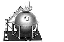
The supplied wind girder is a very thin plastic ring. It is too late for your spheres but for future builds to add a wind girder instead of trying to cut out a ring simply cut a circle and glue the two hemispheres to it. This way you can make the girder as thick as you want. This way the girder can be used as extra glue surface for the leg assembly.
Joe

Like so many builds here, this one has been wonderful to follow. Very nice work.
Thanks all. Was away in the East for the last week. Came back with a bad sore throat and laryngitis. Bummer!
I may think about adding those rings since they let the legs make a square joint instead of a coped spherical joint with a cylinder to a sphere joint. That being said, the ring's not a slam dunk either since the spheres are already well glued and aren't coming apart meaning that I would have to cut an accurate inside and outside circle with the inside being a much more critical geometry.
Just checking in... the sore throat has morphed into one of my bronchitis/sinus infection monsters that stops me cold. I just (finally) got the z-pack antibiotics that will hopefully stop this. Meanwhile, I AM NOT IN THE SHOP!
Sure hope you get better soon! Rest and relax, do what it takes!![]()
Myles,
i hope you feel better. I am sure this up and down weather did not help you. I will post pictures of some of the refining units I am making now and you can see how I did the anchor connections and the platforms. It should help you in the vessels you will be making.
alan graziano
Wow! I hope you get feeling better soon!
Hope you feel better soon! That junk is no fun!
Thanks for the moral support. Now that I have the Z-pac I may be turning a corner.
BTW: I did send the OGRR link to the Heaven Hill Corp Comm person. Didn't get a response yet, but I will.
I need to invent a technical use for used mucus. I am producing quantities of the stuff that staggers the imagination. I should be completely dehydrated. And it's really gross!
I hoe you will feel better soon, Myles!
Andre.
LOL Glad you still have your inventive brain and sense of humor. I have had chronic sinusitis since 1980. Over the last few years my daily treatment has helped considerably, but from past experience, I know it is amazing how much of that stuff the body produces!! The Z pack should put you back on track.
Well folks, I'm finally well enough to get back to the shop. That cold/flu was one of the most aggressive I've had in years. I was running a fever on and off for over five days, it settled in my chest and sinuses. I'm still hacking a bit, but am definitely much better.
So this week I decided to stop working the refinery and install the neat Z-Stuff for Trains crossing gates and signal sets. Of course, my layout posed some unique challenges, specifically that there are multiple tracks that feed to the railroad crossing in question. And my distances and angles between the outside and inside crossing signals made using Z-Stuff's integral IR sensor not work.
To make them work bi-directionally on all these approaches required using 6 Z-Stuff trailside dwarf block signals/train detectors. The system is not quite running correctly yet, but I ran out of time today to fully troubleshoot. Most of the block detectors are signaling properly, but a couple aren't.
First of all, I had to locate the units. I didn't have enough width between track and platform edge on the main street crossing. I added an extension block which I'll camouflage somewhat so it won't be so obvious. I carved the plaster a bit to level the site and screwed it down with the single screw provided.

For the other I had to do some similar fitting. In one case built up the low side after the plaster trimming using some foam core shims. All of this will be re-plastered to fair the bases into the scenery and the bases themselves with be painted with concrete with some other landscaping to further blend it into the layout. That will all wait until it's fully functional.

In another instance, I had to cut the base into the gas station's apron. Here too I will work to blend it into the existing scene.

Here's a view down track showing the right-hand dwarf signals. Notice that the left most one is red. It shouldn't be and the 3rd from the left is displaying red and green at the same time. That's one of the problems I'm having.

In two cases, some of the brittle Taiwanese wires broke off at the circuit board. In both cases I used the Solder Puller to remove the old piece of wire in the through hole and re-soldered a different kind of wire into the hole. In the below it was the black wire that broke off. I've found this to be an ongoing problem with Z-Stuff electronics: very brittle connecting leads.

Lastly I used my tried-and-true termination method still making use of the many euro-style terminal strips that I brought back from Germany when I built version 1. This type actually pulls apart as a connector. I used many of them to join the various roadbed panels which had to come apart for shipment back to the USA. Since I'm not longer wiring the railroad to be dismountable, I had many of these left over. Every piece of electrical apparatus on the layout is attached to junction blocks of various sizes below the layout. This facilitates removal of anything for service.

I was rushing to get things working late this afternoon and was working with the transformer on. I'm using the 14 volt fixed source from my Z4000. I was holding the power and ground leads in my hand while attempting to hook the hot lead to the bus bar that feeds power to all the crossing apparatus when they touched to long. The dinging of the crossing gate bells abruptly stopped. I was under the platform. I thought I blew something out on the crossings, but after dinner thought more rationally and realized that the Z4000 must have circuit breakers for the auxiliary circuits. It does, and it was popped out and I re-set it and everything worked as it should.
I made a very short video of the gates operating. I'm still doing something wrong since they activate and deactivate which the rail car was still blocking the dwarf detector. It's why I haven't plastered anything in yet.
https://www.youtube.com/watch?...ture=em-upload_owner
Tomorrow I should have it all figured out. If not, I'm calling Dennis Zander at Z-Stuff. Then it's back to work on the refinery.


Those euro-connectors are great. I use them everywhere. You can get them for almost nothing on eBay. I buy them by the dozen.
They really work best when you also use wire-end ferrules. You need to invest in a professional ferrule crimp tool if you're serious about this. The crimper applies the correct pressure and shape to make a secure joint. I've had no connection failures due to terminations using this method. You can get all of it from Ferrules Direct (http://www.ferrulesdirect.com).

I use red and black large gauge size for all my power bus wires, and the smaller white ferrules for all the signal lines. You can get them in many sizes, styles and colors. When using very fine gauge wires that seem too small for the white ferrules, I will double the wire over so it makes some more bulk before crimping. It's not ideal, but the wire won't pull out.

For us cheapskates, another approach to preparing wires for screw-in connectors is to tin the ends of the wires with solder. The "folding over" trick that you mentioned works well with this technique.
Trainman2001 posted:They really work best when you also use wire-end ferrules. You need to invest in a professional ferrule crimp tool if you're serious about this. The crimper applies the correct pressure and shape to make a secure joint. I've had no connection failures due to terminations using this method. You can get all of it from Ferrules Direct (http://www.ferrulesdirect.com).
I use red and black large gauge size for all my power bus wires, and the smaller white ferrules for all the signal lines. You can get them in many sizes, styles and colors. When using very fine gauge wires that seem too small for the white ferrules, I will double the wire over so it makes some more bulk before crimping. It's not ideal, but the wire won't pull out.
A trick I learned - the smaller ferrules will fit inside larger ones. This works better with the larger opening size European connectors.
Joe
Glad you are almost over the nasty bugs, Myles!
I have seen the ferrules on wires many time, but never put any on myself. Thank you for the information on the ferrules and the crimper. Now I have used Pete's method before, with good results.
That's a good idea of using the smaller inside the larger. I'm going to try that.
I interacted with Dennis Zander at Z-Stuff about my setup and he gave me some advice. The front crossing signal was not functioning. When I removed it from the layout I found both the red and black power leads to be broken off at the circuit board. Before I got it to the bench the blue and yellow wires also separated leaving only one white wire connected to the board. I re-soldered all four. This was the 3rd time I've had to refasten wires on these units. I let Dennis know that this was a problem. He said that he thought they had it solved. I don't think they have. I found the same problem with the hook up wires inside his switch machines. These are made for him in Taiwan and I believe that a finer stranded wire could be used that would flex better without cracking off.
Dennis suggested that I use diodes on all of the dwarf sensors so they don't interfere with each other. I've ordered diodes from Jameco Electric which is my go-to place for electrical components.

As I've noted before, I've trained thousands of people in high quality soldering so fixing is not a problem. But I'm sure there are customers who do not have these skills.
When running my Santa Fe through the sensors to make the gates work, the engine and several cars kept derailing on the latch side of the swing gate. Something had shifted and I couldn't manhandle the gate back into alignment.
 t
t
The bump was too much for the lighter trucked machines. This is a bad spot for a derailment since it leads directly into the tunnel. I wasn't really happy with this junction for a long time and decided to bite the bullet and do some M.O.W work by ripping up the track across the gate gap, install a new piece of straight track, and after the Liquid Nails that's holding it cures, cut a new diagonal break to enable the gate to open. Couldn't lift the track in one piece so I first tore off the rails leaving the ties firmly attached to the VinylBed below. Kind of looks like some real abandoned track...

I repainted the new rail after lightly steel wooling the rails to accept paint, shooting it with rattle-can Tamiya gray primer, and then with acrylic rail brown. I forced dried both coats with the hot air gun and cleaned off all the rail heads. I again used Liquid Nails to glue down the new rail and weighted it to keep it flat while it cures.

Tomorrow I'll solder jumpers on the left end which has no track pins. You can't put in a 10" piece of track with track pins when the tracks on either side are glued down. So I put pins on the right side and will solder 12 awg bare copper jumpers on the left side. I wire brushed the track area before gluing it down to prepare it for soldering. Once the track is soldered and secure, I'll make the track cuts.
Since I didn't used to have a problem with this joint, I'm wondering why now it misaligns. I suspect there's been some atmospheric changes which caused the swing gate to change somewhat. It only has to move a 1/16". That being said, I should probably expect that when winter comes it will move in the other direction. Either way, the track will fit more precisely than the old one.
Last thing I did today was to start assembling a full-size, 1:48 scale set of plan drawings for the refinery. The Plastruct kit's plans are probably HO scale, but I'm not sure since the multiplier was 185%. I need full-size plans for a couple of reasons not the least of which is to see how the out-of-the-box scheme will fit on the layout. It's really big!
I made many passes on our scanner/printer to put it into the laptop and then printed out the pieces at the aforementioned enlargement factor. There were some gaps in my scanning of more than 1/2", but they won't affect much. I'm also using the plans to design the pipe runs, cut work platforms, etc. The enlarged and Plastruct plans are both seen in this image. I ran out of Scotch Magic Tape and resorted to using blue tape.


Lots of stuff to cover today. Finished up the M.O.W. work on the track and tested it...A-ok. Finished cobbling together the 1:48 scale refinery plans and tried them on the layout in the selected spot. And got back to work actually building refinery unit ops spending lots of time sanding the mating edges of all the vessels to make them appear as a welded whole. Finally, got back to building the heater unit with its dubious transition piece.
With the Liquid Nails set solid, I moved my RSU onto the train platform and quickly soldered the jumpers across the pin-less track joint. I use paste rosin flux when doing rail soldering to add some more oomph to the rosin core solder I'm using. The RSU heated the joint in a couple of seconds, got good solder flow and kept the RSU hand piece tweezers on the jumper until it solidified, then moved to the other end and did the same thing. Very simple, very easy.

I cleaned the excess flux off with 91% isopropyl alcohol and then painted the bare areas with rail brown.
With the rails firmly attached, I took the Dremel with the Flexi-shaft and hung it from my portable Dremel hanger and made the diagonal cut through the gate gap. The tracks are now aligned perfectly both horizontally and vertically.

Time for some re-ballasting. I used alcohol/India Ink to pre-wet the roofing granules, and then liberally applied W-S Scenic Cement. I think I may have used too much ink since it looks a bit dark. Of course it's not dry. Tomorrow I'll know better if I did it right.

I did a test run and the Santa Fe and its train ran through the new track perfectly. With the train running I made another short movie showing gate activation.
https://www.youtube.com/watch?...ture=em-upload_owner
I finished taping the massive amount of paper together to make the 1:48 Refinery plan. I then brought it to the layout and supported it a bit to see just how it would fit.

From this view you can see how wide it is. It protrudes into the open space a bit too far. But you can also see that there's plenty of room on the left. In fact, I'm going to re-design the plan to allow it to spread leftward and be less wide. I'm going to move the high pressure side-by-side, move the location of the big storage tank, turn the longitudinal pressure vessel so it would be parallel to the tracks and re-arrange the distillation tower and heater. This should reduce width about 10 inches. I still need room for the cooling tower, and some offices. I ultimately want to fill in all that open space on the left and extend it out at least a foot.

Back to the units. I first used the belt sander to knock down the gross irregularities in the joints. The belt sander isn't ideal for working with ABS since it melts it as much as sands it. You need a very light touch to keep it from making a mess. Here's a pressure sphere after the belt sanding first step.

Then I added a lot of elbow grease starting with a 100 grit sanding stick and working my way up to 600 grit. I keep dipping the sticks into water to keep them from loading up. The final result will look okay when painted. While I could use some filler to remove the very last vestiges of a joint, I'm not going to worry about it since this who display will be over 10 feet from the viewer.

I did the same thing on the horizontal pressure vessel and the big storage tank. Then I went back to work building with the heater. The transition piece is a thin bit of ABS that was vacuum-formed by Plastruct to a pointed cone. You have to measure the two diameters and cut it to a truncated cone. I measured the diameters with the calipers. made this mark on the cone, and then used the surface gauge to draw a cutting circle. I cut the large diameter with a scissors, glue it to the base with Bondene, and then measured for the small diameter. This was cut with a razor blade.

I attempted to glue the stack with bondene, but it didn't want to be secure. Not seen is a styrene disc that forms a surface upon which the stack can glue. Another way to do this would be to make the upper disc with a hole and have the stack go through all the way to the bottom thus supporting it in two places. I didn't do that since I just though about it. To make it more secure, and, equally as important, to really secure the transition piece so I can safely remove all that excess that's hanging over the edge, I used 30 minute epoxy to hold it all together.
Here's the assembled unit before finishing which will take place on Monday.

Notice too that I added an ABS baseplate that will get the NBW treatment like the distillation tower and it too will get a 1/4" "Concrete" base. I just checked and the epoxy is solid as a rock. I'll use epoxy with micro-balloons to fill in the remaining gaps at the transition piece top.
Next session I'll finish up this piece and move onto one of the more complicated structures; the reactors and their "concrete" and structural steel support frame. With the main units built, it will be time to add platforms, ladders and valving.


Myles;
Please see below:
Back to the units. I first used the belt sander to knock down the gross irregularities in the joints. The belt sander isn't ideal for working with ABS since it melts it as much as sands it. You need a very light touch to keep it from making a mess. Here's a pressure sphere after the belt sanding first step.
The best tool here is a finish sander like the Porter Cable Speed Block. Unlike a random orbital sander which s design for fast material removal the finish sander is designed for the last part of the process where light removal is required. For severe scratches I start with 60-80 grit then work my way up to 150, sometimes 220. I tend to like the rough appearance plus the rougher surface holds paint a lot better. Note - if you plan on placing decals after paint be sure to spray with Dullcote or Krylon clear coat first or decals will develop the silver blotch issue due to the rough surface.
I attempted to glue the stack with bondene, but it didn't want to be secure. Not seen is a styrene disc that forms a surface upon which the stack can glue. Another way to do this would be to make the upper disc with a hole and have the stack go through all the way to the bottom thus supporting it in two places. I didn't do that since I just though about it. To make it more secure, and, equally as important, to really secure the transition piece so I can safely remove all that excess that's hanging over the edge, I used 30 minute epoxy to hold it all together.
The tank shell and cones are grey ABS - Bondene should have worked. My guess is not enough glue surface. If the cone overhangs the tank shell a little bit then cut a circle of same diameter as the tank shell. However, glue it to the inside of the cone first then glue the assembly to the tank shell. If you are using styrene for the circle then use Plastic Weld to bond it to the ABS cone.
Joe
Myles/ Joe,
sometimes I have found it best to fit up the heads and shells the best you can and not sand at all. Since this would be a welded joint, you might want to leave the line rather than erasing it.
alan graziano
My joint was too large so filling is warranted, then I'll scribe a line which would serve as that weld.
In fact, yesterday I did add the filler: 5 minute epoxy thickened with micro-balloons. I'm letting it cure all night and will sand it later today.

I made another faux concrete base and epoxied the heater to that base. That too cured all night. I bought new scroll saw blades at Lowe's. This time I got some that were coarser than the 28 tpi blades that I was using. For thin stock the fine blades were okay, but they broke constantly on anything with any thickness. It was very frustrating. I first went to THD and they didn't have any blades without pins in them. I need plain blades. I then went to Lowe's and got them.

I then enlarged and taped together all the elevation drawings of the units to use in aid to piping and platform locating. I asked Al (on another post) about the beautiful tie-down anchor bolts he added to his distilling tower project. Notice on the Plastruct drawing, there is no detail at all about how this tower is held to Mother Earth.

I also asked him about curving Plastruct railings. I've had a tough time forming them and want to know if there's a secret technique he uses. I tried softening them with a heat gun, but I overheated some and they distorted badly.
Notice on the drawing, when printing with Adobe Illustrator, I lost some of the image on the page tiling and had to fill it in by hand. There's an "overlap" setting on the print, but I wasn't getting it right. The drawing isn't very clear, but those various side cut tray takeoffs should probably connect outside of the tower. The drawing looks like they loop back into the tower and that makes no sense. The ladders included with the O'scale kit include cages which aren't shown in these (originally) HO drawings. Someone said this kit is not for the fainthearted. No kidding!!


Myles,
when working on small tower diameters (2-1/2inch diameter and smaller), I usually make the handrail by using angle or tees for the posts and styrene strips for the top rail, mid rail and kick plate. You can roll the strips in your fingers, allowing you to build curved handrails easily. Make sure you glue the posts first and let them dry so the will stay vertical and not move when you glue the rails onto them.
alan graziano
Thanks Al!
I decided to use a hybrid of your methods. I made the platforms with straight sides with the width the same as the Plastruct post spacing. I then cut or attempt to notch/bend the rails to conform to this shape. I used Bondene to adhere everything, followed up by med CA to reinforce.
First up was chucking the heater into the lathe between the chuck and a steady rest and sanded off the excess epoxy filler using progressively finer sanding sticks. I then scribed some seams at the transition and above to simulate its "real" construction. Not perfect, but Al says these aren't perfect in real life.

I got back to work on the distillation tower. I scribed the various levels for platforms and pipe fittings using the surface gauge on the surface plate. After laying out the shapes for the platforms, I engraved all the lines deep enough to crack the ABS on the lines. To get the inner diameter I measured the tower diameter with the digital caliper, divided by 2 and set caliper to this new number, and then set the dividers between the caliper jaws.

To ensure that I had a reasonable fit, I attached a small piece of adhesive sandpaper to the tower and used it to final shape of the opening.

I laid out the vertical braces out of the same thickness ABS stock. I finished them up on the NWSL precision sander so the mounting edges were all square. I fastened the tower into the woodworker's vise I have attached to the modeling table to stabilize the tower while I held the bracket in place and applied cement. Went back and reinforced glue joints with med CA. The bottom platform had to align with the upper so the ladders would align AND they needed to be positioned to clear the tray downcomers that will go on later.

For the railings I first attempted to notch and bend the rails to give me the shape I needed, but most of the thin rails broke. So for the rest of them on the four sided platform, I installed each piece and glued to thin rails together after the kick plate was adhered to the platform. This looks easier than it was. Again, joints were reinforced with CA.

On the bottom platform, I was more careful with the notching and bending and was able to put the 3-sided piece on as a single item.
I also drilled the top for the pressure relief valve and the main top downcomer. Marks were made on the sides for the other side taps. I'm going to add some flanges on the support brackets to give them some more details.

Next week work will continue.
Oh... I started today's session still trying to find out why one of my Z-Stuff crossing gates is not responding to the trigger signal. I had it apart and it works perfectly. Dennis Zander has been giving me some pointers, but so far, nothing is making it go as it should. I am nothing if not persistent.


Myles:
Looking good!
Joe
Alan Graziano posted:Myles,
when working on small tower diameters (2-1/2inch diameter and smaller), I usually make the handrail by using angle or tees for the posts and styrene strips for the top rail, mid rail and kick plate. You can roll the strips in your fingers, allowing you to build curved handrails easily. Make sure you glue the posts first and let them dry so the will stay vertical and not move when you glue the rails onto them.
alan graziano
Alan:
What size tee do you use?
Thanks
Joe
Joe,
i use 1/8 or 3/32 inch tees.
alan graziano
Alan:
Thanks
Up till now I have been using the HRS-24 handrail stanchions - expensive way to go and never really liked the looks.
Joe
According to the catalog, the HRS-24 is a 1:16 stanchion. They don't seem to show one for 1:48. I've made my own out of brass drilling holes in brass angle. Soldering them together makes the best looking rails, but much, much slower and more difficult.
Got back to the shop today. My daughter was at a conference in Washington D.C. so I was tasked with carpooling the boys to various activities. Yesterday we took the grandsons to see Guardians of the Galaxy Vol. 2. Lots of fun, exceptional CGI with thousands of people employed making it. You have to sit to the end of all the credits to see all the vignettes that are included.
Today I did some more distillation tower work. I decided to do some Internet research and looked at tower design and noticed that many had a platform on the very top the was to access the pressure relief valve that sits up there, and access the davit which is used to hoist components in position during maintenance. So I scratch-built one and installed it. I had a limited supply of Evergreen structural shapes that would would so I cobbled together what I could. The I-beams I used for the sub-structure was a little overkill. You have to cope the pieces that lie between so they nestle together.

I glued on two vertical supports to the tower and shaped them so the platform would nestle tightly to the supports.

These probably should have been structural shapes, but I didn't have one of the correct size.
I then added some Evergreen styrene angles underneath to brace it all up. It works and adds another level of "busi-ness" to the structure. I also added a series of styrene bands (0.015" X .125"). I noticed in my research that there are reinforcing bands that serve as places where pipe/ladder brackets are attached to the tower.

I also added some small styrene bars to the underside of the platform supports to add interest.
I went as far as I could without the ladder brackets, nozzles and manholes from Plastruct. They should arrive in a couple of days. So I started work on the "concrete" foundation structure that supports some of the other unit ops.
Here's the plan of this foundation.

The base is made of 3/8" square ABS. The cross pieces are 1/4" ABS. I cut all the parts using an Xacto saw with my miter box fastened to the workbench. The miter box is wearing and no longer produces dependable square edges. So I clean them all up with the NWSL sander, constantly checking that they're still the same size.
I employed my magnetic building tray to hold parts in place and square.

After the cross pieces were installed, I clamped it up for the 90 degree pieces. I first used Bondene to glue it up, and then reinforced with med CA and accelerator.

I just pulled the clamps and found that I had glued one side reversed from the other. I have the 1/4" stock set back from the front edge (or that's how I was supposed to do it.) I have two choices; break it apart and re-glue to the correct side, or let it alone since it will so far back that viewers won't notice. I would have thought that the model would have included enough 3/8" stock to build the whole foundations, but they didn't. There was one piece that was exactly the amount needed for the vertical supports.

Upon this goes 3/8" I-beam and cross beams. I'll do that tomorrow. It's a fun project!


Myles,
The structures are looking good. Enjoy the project.
alan graziano
Thanks Al! You're the master and I appreciate your critique.
Well... my AMS kicked in and I broke the incorrect joints and re-glued it in the same orientation as the other side. I then added the I-beams and made another small error. If you'll notice in the drawing in yesterday's post, the I-beam extends out beyond the concrete pedestal. I glued them flush. So I added a little extra bit to extend it since this is the side that the ladder goes. I made the other end flush since I was out of that size I-beam. Plastruct is not generous with some of these raw materials. I had exactly the amount needed for the pedestal and have found the situation with the I-beams.
I also closed off the tops of the hollow "concrete" pedestal legs. These wouldn't be hollow and the I-beams didn't entirely cover the open ends.

Here's the I-beams and the thin ABS mounting surface applied. In reality, there would be more structural steel underneath the platform, but for the model this was fine. Besides, as I noted, there's no more I-beam stock.

Tomorrow, I'll have more time and will start installing some of the upper works and the condenser vessels that will go on this structure.


Still waiting on my pipe fittings from Plastruct so I'm going as far as I can making up vessels and finishing the condenser platform.
Before I got started I had to go to Lowe's and replace a workshop light. It had some LED florescent replacement bulbs I bought at Costco. It was flickering yesterday and when I tried wiggling it, it started sparking and the end connectors caught fire. I perceived that catching fire is generally frowned up in ceiling lighting. I shut it off. After inspecting it I found that it was burning at both ends so it clearly was breaking down internally. That's the trouble with LEDs (or should I say the myth). While the lighting elements themselves, the LED, will last 10,000 hours, the circuitry that turns 110 VAC to some DC value that the array needs will not last 10,000. In this case it lasted a little over a year. I replaced it will an entire LED fixture. They produce greater output than fluorescents with significantly lower energy use. We'll see how long this one lasts.
I glued the ends on the three remaining kit vessels. Two have domed ends that are Plastruct parts, and the other has flat ends formed from sheet stock. After gluing and setting, I sanded the ends to even out the seams. The smallest of the three fit into my lathe chuck so I was able to spin that while sanding which produces very nice results.

The smallest one suffered a near calamity. While working on the pedestal, I had unknowingly knocked over my bottle of Tamiya thin cement which now contains a mixture of Bondene and Plastruct plastic cement. I had screwed the lid on, but apparently not tight enough. It wasn't fully sideways, but tipped enough that it leaked. And of course Murphy was right there watching the whole thing. When I finally realized what happened, the small vessel's bottom was fully soaked with solvent cement and it did some damage. I let it all dry, and then re-chucked it in the lathe and re-sanded it all until the blemish had disappeared. Whew!
I laid out the tanks for their respective valves and pipes. I'm using V-blocks, a surface gauge and my granite surface plate to lay out the locations. I pick the dimensions off the full-size prints with my caliper and transfer this to the surface gauge. There's no reason for any of this to be specifically accurate, but I just try to work that way. But... the pipes should all come off the center lines AND they should be vertical and in-line, so there's that.
The horizontal center line was already laid out in this image. Here I'm adding the cross lines to the two equi-distant (from the ends) openings are the vessel bottom. This is the big vessel and has 6 penetrations: 3 on top, a man hole on the side and 2 on the bottom.

After prick-punching the cross line, I partially drill each hole with a small drill, and then, again using V-blocks, drill the holes in the drill press. The pipings is 1/", but I'm drilling with a .126" number drill that enables the piping to enter much more easily.

Can't add any piping yet, but I was playing around adding some stuff together. According to the drawing this center hole is actually the relief valve line, not a gate valve.

Finally, I got back to building the structure which will hold these units. I cut four small H-beams for the verticals, and glued the long horizontals. I was in the process of cutting the short horizontals when I ran out of time. Have to wait until Monday. I needed pressure to hold the pieces together and after messing with quick clamps reverted to good old reliable gravity clamps.

Speaking of gravity... has anybody been watching "Genius" on National Geographic channel? Story about the life of Albert Einstein. Very interesting! Speaking of Einstein, just now another prediction of General Relativity was proven by being able to measure the mass of a star based on the gravitational lensing of a star that lies behind it. The star in question was a white dwarf 14 light years from Earth. Using Hubble, astronomers watched it eclipse a star that lied behind and then that star reappeared by the exact predicted amount which then enabled them to derive the occluding star's mass based upon how much it warped space-time. They observed it over several years. It took until now to do this because previous telescopes simply weren't sensitive enough to measure the tiny amount of light bending. Pretty cool!


Happy Monday!
Did more work on the pedestal finishing up the steel work for the upper deck. Then UPS delivered my Plastruct pipe fittings. So I went back to work on the distilling column.
I initially picked up the wrong size vessel footings and thought that the upper deck was too wide and immediately measured and cut out a notch on both sides so these footings would fit. Then I attempted to fit the vessel to them and immediately realized that these were way too big and searched for the right sized ones. So now I have two erroneous chunks removed from the decking and found little pieces of ABS to refill the gaps and then used Tamiya filler to make it all better. Then I glued the correct footings in place. All of this gets painted of course.

One type of new pipe fittings I got are nozzles which are the flanged extensions that come out of pressure vessels to make pipe connections. Since I'm spending so much time on this project, I wanted to do it as best I could.
Also, on the very top of the tower is a davit which is used to lift components into place for maintenance. I thought it needed a pulley at the end so I fabricated one out of excess PE fret and turned little brass pulley and a piece of -032" brass wire. I really don't know what's really going on up there since most of the pictures I find of these vessels are taken too far away to make out what's going on. The post is assembled from Plastruct #4 piping. Those are True Details resin NBWs at the ends. Whether it's prototypical or not, it does add interest.

I installed all the pipe nozzles in their various 1/8" holes. I filed the area right at the apex of the curve so the nozzles would fit more closely on the curved tower surface.
Now it was time to build some man ways, access ports so humans can get inside for maintenance. I used the larger #8 nozzles and made some 7/16" disks to serve as covers. I punched these out using a hollow punch I got from Harbor Freight. I mentioned this before when building the substation, but these Chinese tools are really not very good and do not hold an edge, but they do work in a pinch.

After gluing the covers to the flange, I chucked them in the lathe to true up the edge and then engrave a ring on the face that would be the bolt circle.

With a divider set at the radius of this circle I set out six pin pricks to serve as bolt locators.

After drilling with a 0.032" drill, I installed Tichy Train Group small (1.125 scale inch) NBWs and glued the assembly to the tower at the proper pre-drilled locations.

In this case, instead of filing the tower curve to help the man way to fit, I milled little bit from the back of the fitting to relieve it around the curve and help in seat better.
I think these man ways are a bit out of scale. I think they extend too far out and their diameter is too small. They're 16" scale inches. I don't think a human adult can squeezed through that space. They probably need to be at least 24" scale or bigger. But again, they add interest, and Plastruct gave no parts or specific instructions about making them other than a few callouts on the kit drawings.
Meanwhile, I did order enough of these #8 nozzles since I didn't realize at the time that I needed them for both pipe attachments AND man ways. Instead of ordering more, I'm going to make my own out of the large diameter pipe and some of my cut discs.


Boy! I wish I had Al's experience building refinery equipment. I got the ladders and piping into place on the distilling tower. It could have been better. The Plastruct ladder supports interfere with the Plastruct ladder cages. I placed the ladders too close to the platforms and after I installed the ladder supports and therefore didn't have enough room for the ladder cages. I have pipe valves impinging on adjacent piping. And so it goes. If I were to make another one of these, all of these challenges would have been solved. But I'm building only one. The other problem, as I see it, is that it's a very narrow column with a lot of stuff going on it. I would be easier to get them all nested together if it was a larger diameter tower.

I did spend over an hour doing a very annoying job. The tower fell over and the glued connections at the ends of the rails on one section of the lower platform's railing. It needed reinforcement. I first tried a piece of bent fine guitar string so it wouldn't be too noticeable, but it was impossible to get it hold still long enough to glue it with CA. I then turned to making some very small brass angle stock using PE fret material. This too just was not working to the point that the rest of that rail section broke away. I replaced the section with a fresh piece after pre-fastening the reinforcing angles and this time got it all together. You can see the brass pieces in the picture, but you won't when it's buried in the chem plant at the back of the layout. I really have better luck actually soldering the whole deal out of brass, including the platforms. If I made another one of these, I'd use brass.
Here are the ladder cages completed and waiting for paint. I'm going to prime and paint all the unit ops at the same time since it's going to be with solvent paints and that's done outside (until I get my spray booth... still working on that one).

I bought the transparent ladder supports, but these do not work with the ladder cages. I had to notch the cages to let the supports clamp to the ladder, but even there is was sub-par. Also, by staging the ladders too close to the platforms, the cages again, needed to be trimmed to clear. I'm going to paint the ladders safety yellow and the rest of the tower to be bare metal metallic by Tamiya. Everything will get a Tamiya grey primer coat first.
Since I ran out of Plastruct man ways I scratch-built one using some of the largest tubing and the same discs I used for the factory ones. I again used the sandpaper on vessel method to impart a curve to the bottom of the man way that would match that of the same vessel.

I finished adding all the tank bases and trial fitted them on the pedestal. I'm having to figure out the piping for them. The P&ID drawing is a bit cryptic.

I also cut apart the plot plan and rearranged the unit ops to make it longer and less wide. I like how this worked out. It no longer juts too far into the open space in the railroad's mid section. It uses more of the linear space, and still leaves plenty of room for any other things I want to build in that space (maintenance and ops buildings and a cooling tower). I also found a left over piece of the tubing that I used for the stacks on the distillery's boiler house. It's about 20" tall and will make an excellent flare tower. I turned the two HP storage spheres 90 degrees as I did with the mechanizer reflux drum (the big horizontal vessel). I moved the heater and the big liquids storage vessel towards the track so the whole thing is much thinner. It now extends into the open space and 10" which is about what I anticipated it should be. It may or may not take more piping and I hope I won't run out. It looks like I'm going to have to fabricate about 4 more man ways. Now that I know how to do them, it shouldn't be too much work.

The big storage vessels will be white. The long reflux drum I'm thinking of making red. The heater will be black and the distilling tower bare metal. The other three vessels will be some mix. The flare tower will be broad red and white stripes. I'm thinking of pupping a simulated flame LED up top with some cotton to show some minor waste flaring.


You're making a very good fist of it, Myles. ![]()
Myles,
I think you are doing a fine job on this. The detail on the flanged bolts is far in excess of what I do. That detail looks great. Keep plugging away and enjoy building.
Alan Graziano
Myles,
This is just another of your tremendous models and excellent documentation to boot!!
Trainman2001 posted:Speaking of gravity... has anybody been watching "Genius" on National Geographic channel? Story about the life of Albert Einstein. Very interesting! Speaking of Einstein, just now another prediction of General Relativity was proven by being able to measure the mass of a star based on the gravitational lensing of a star that lies behind it. The star in question was a white dwarf 14 light years from Earth. Using Hubble, astronomers watched it eclipse a star that lied behind and then that star reappeared by the exact predicted amount which then enabled them to derive the occluding star's mass based upon how much it warped space-time. They observed it over several years. It took until now to do this because previous telescopes simply weren't sensitive enough to measure the tiny amount of light bending. Pretty cool!
Yes, my wife and I have been watching and enjoying the show. She is a Chemistry teacher and her inner "geek" has come out a couple times. I have to admit it is fun watching it with her because she is way more familiar with some of the names than I am. Most of the groundbreaking scientists at the time had interactions with each other. It is fun seeing how a discovery by someone else aided the research of others.
Your work is amazing! I really enjoy following your progress.
Thanks all. This is a very challenging project. We've been watching the Genius program On-Demand, generally the commercials are a little less.
Did a lot of finicky pipe work today. I'm having trouble with the plans. There are dotted lines indicating the structural steel that lies under the upper platform AND more dotted lines showing hidden piping. It's quite challenging to figure out which is which. Furthermore, the plans show the center top pipe leading to the overhead top discharge from the distillation column, but the booklet photos show this center top position as a relief valve location and the line running straight into the ground. I'm using the input from the column in my design. The column needs a receiver for the top flow and it's a bigger diameter line (gas vs. liquid) and the plans show this. Where I'm having the most trouble is figuring out what all the underneath piping is.
I added the lines to the receiver. After messing around trying to get the piping to stabilize, I finally add some "welded" braces to it since there was no place to put a Plastruct pipe support. I don't know if this is prototypical, but I really needed it since the piping was very fragile and kept breaking loose. I find the white ABS piping does not weld as securely as the gray. You think it's adhered and then suddenly it just lets go.

I also had to fit one of the bottom entry pipes coming from the smallest vessel below. This pipe isn't going to be connected until the tanks and platform are separately painted. I had to tape the receiver into position to hold it steady enough so I could measure the distances involved.

I added the pipe to the medium-sized receiver. This too will be separately painted. Due to the restricted overhead space, I used and angle valve. This was not included in the kit. I had it leftover from the boiler house project. I added a drop of medium CA under the S-curve to stabilize this pipe also.

I decided to start building the pump sets. They're not all piped the same. This first one feeds the big storage tank. It has two gate valves and two check valves on the discharge side. The instructions say (and I quote), "Assemble the pumps". That's it! It doesn't say that there are not holes for pipe fittings. It doesn't show where the intake and discharge sides are. It doesn't talk about how big or thick the base should be, or the spacing of the plumbing. I drilled them out 1/8", but then realized that I wanted to use the small diameter pipe fittings so I glue in the small diameter tubing in the holes.

I added the discharge side piping, but after checking the plans had the T facing the wrong direction.
 \
\
Here's the completed array with the check valves and the piping facing in the correct direction. If I wanted to be silly, I would cut spokes in all those valve wheels, but I don't want to be silly since this stuff will be buried in piping.

I'm going to build all five pumping stations now since I'm getting the routine down. Next up will be the large demethanizer vessel. It too has the usual array of nozzles, valving, and piping.


With the little time I had today I continued building pump stations. I got three complete and one more than half leaving only one more set to finish them up. The last set has a different configuration according to the plot plan.
I'm getting sort of an assembly line working here. I'm doing the drilling before the motors go on the base so I can clamp the pumps more effectively in the drill press. I measured all the pipe pieces and cut them ahead. I've standardized on the exact placement of the pumps on their bases and the bases on the base board. There's not specifics about how this should be done, but, you need to have them parallel and at the same edge or the piping goes in out of square. I'm also short of check valves and will make some out of standard valves.


I have a few odd-sized pieces of OSB and found enough that I can puzzle together to make the base for the entire refinery complex. It will consist of four pieces all joined together. That was a big relief since I didn't want to have to buy another 4 X 8 sheet which I would only use about 1/3. I'm running out of things to build with OSB. It's a little bit of overkill to use it for a spray booth. I'll do the cutting some day when #1 is out of the house since the circular and saber saws raise on heck of a ruckus. I use 3M sound deadening ear muffs, but upstairs doesn't have that.

Access to this requires an OGR Forum Supporting Membership

")
")