Lee, it was interesting that they used crushed clam shells as ground cover throughout the plant. I also developed and taught a course on locomotive safety there. They had two Alcos (RS2 & RS3) which they abused to the point of failure. They didn't just make polyethylene beads. They also made PVC, and for this they needed chlorine. They received it in tanks cards. They would run the engines without the train brakes hooked up. Tried to start too many loads with the small switcher leading to burned tires and deep gouges in the rails. One time the slippage was so great that they slammed the throttle shut from notch 8. The resulting back EMF blew the generator apart. So I was asked to run a course. During the research I found out that certified operators were letting warehouse men run the engines on night shift so they could have fun "running the trains". All of these practices were stopped. They handled enough chlorine to be a big hazard for the entire region.


Only had an hour in the shop today so not much got done. Did a little more finishing of the gantries, cut and attached the base plate, and glued up the stock that would be the "concrete" pads. I measured and cut the top cross-members, but will wait until the mounting pads are installed so they'll be more stable standing up.


HV Gantry 03


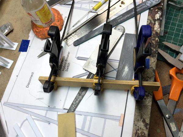
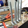
From this sandwich, I'll cut off the four concrete bases. This is German High Density Fiber Board. It's very hard and very smooth textured. I used it for the fascia boards and bought it while still living there. It's a higher quality than the Masonite I've found here in the USA. All of the German lumber was very high quality. Would you expect anything less?

HV Gantry 04


Tomorrow I'll add these bases. I have a minor loco repair I'm also going to do. HV gantries should be done next week.

Attachments

Images (2)
  • HV Gantry 04
  • HV Gantry 03
Originally Posted by Trainman2001:

Lee, it was interesting that they used crushed clam shells as ground cover throughout the plant.  . . . . They had two Alcos (RS2 & RS3) which they abused to the point of failure. 

The crushed shells as ground cover was just pragmatic.  You could literally get them by the ton for nothing along the coast.  They were okay in that roll as long as you did not try to go barefoot . . . 


It wasn't just locomotives that big industries abused.  A lot of the industrial plants along the gulf coast I worked with loaded equipment up to levels and neglected equipment beyond anything a utility company would dream.  Whereas a utility will load a transformer like the one you modeled up to a peak level that will give it an expected 65-75 years of service lifetime, I've seen industrial plants burn them up in only seven and a half years, just overloading them 24/7 and running them very hot.  They also do very little maintenance - as one plant manager told me "Why do maintenance?  Everything on it will last at least ten years in you don't, except the core, and we'll burn that out in about eight and just scrap it . . . " 

Originally Posted by Lee Willis:
Originally Posted by Trainman2001:

Lee, it was interesting that they used crushed clam shells as ground cover throughout the plant.  . . . . They had two Alcos (RS2 & RS3) which they abused to the point of failure. 

The crushed shells as ground cover was just pragmatic.  You could literally get them by the ton for nothing along the coast.  They were okay in that roll as long as you did not try to go barefoot . . . 


It wasn't just locomotives that big industries abused.  A lot of the industrial plants along the gulf coast I worked with loaded equipment up to levels and neglected equipment beyond anything a utility company would dream.  Whereas a utility will load a transformer like the one you modeled up to a peak level that will give it an expected 65-75 years of service lifetime, I've seen industrial plants burn them up in only seven and a half years, just overloading them 24/7 and running them very hot.  They also do very little maintenance - as one plant manager told me "Why do maintenance?  Everything on it will last at least ten years in you don't, except the core, and we'll burn that out in about eight and just scrap it . . . " 

Sounds like the change in philosophy of the power company I worked for.  Originally we maintained everything as best we could and updated a lot.  Then in 1995, they wanted to become 'the low cost producer'.  That is when they changed to the 'run it until it smokes' philosophy.  That is also when they permanently laid a bunch of us off. Many other power companies did the same, and I ended up back in telecommunications where I started out in 1976.

Originally Posted by Mark Boyce:
 

Sounds like the change in philosophy of the power company I worked for.  Originally we maintained everything as best we could and updated a lot.  Then in 1995, they wanted to become 'the low cost producer'.  That is when they changed to the 'run it until it smokes' philosophy.  That is also when they permanently laid a bunch of us off. Many other power companies did the same, and I ended up back in telecommunications where I started out in 1976.

Its never fun to be on the downward side of downsizing, but it was an industry-wide trend that hasn't stopped yet.  


What I find most interesting is that while traditional utility folks think industrial plant managers who treat equipment like this are "so stupid," plant managers look at how utilities load and service equipment, shake their heads and say, "They're wasting so much money."    The traditional reason utilities didn't load equipment to the point it would run hot, and "took care" of it was they didn't want the service outages that would occur when it failed.  But increasingly smart systems mean that doesn't happen anyway.  It actually makes sense to buy a small transformer and just use if up at high loading levels in only a decade or so, and then just replace it.  I call this a "buy burn and bash," philosophy and wrote about it in one of my books: from the right perspective even a half-million dollar transformer should be looked at as a disposable component to be used up in the process of running your business. 

Last edited by Lee Willis

Good discussion! 


I did a little substation work, getting the G hv gantries finish sanded. I also cut and final shaped the concrete pads.

 HV Gantry 05

I was going to epoxy them today, but instead got to work on another small project. I'm planning on selling my Lionel late-model F3s (the hi-scale ones produced in the mid-2000s), but one of the B units had a missing swing hanger that broke off way back when I was first unpacking the engines when they were new. I was sure that I could make a new one and install without problems. Funny how you think that sometimes and it couldn't be further from the truth.


Here's a good truck showing the parts. 

Undamaged Santa Fe B Truck


What I didn't know until I got into this was that these parts are all die-cast. This greatly complicated drilling holes to receive the new parts.


I fabricated the new swing arm out of 0.030" brass. I figured I'd try this first and then go to styrene if that didn't work. I drew the parts on Coreldraw and made cutting templates. I used the jeweler's saw with the fine blade to cut the brass and then finished it with a diamond wheel mounted in the Dremel flexi-shaft. I shaped the ends so they would fit into small holes drilled in the brackets that were remaining attached to the truck's side frames. I had to prick punch the bracket and that's when I found out that it was cast metal, not plastic. When I tapped the punch with the hammer (lightly mind you), the bracket broke away from the truck, and, to make matters worse, the swing arm axle fracture into two pieces.


The truck now looked like this.


Damage to Santa Fe B Truck


Since I had the bracket, I was able to drill it when off the train by holding it in a pair of forceps. I was going to put the axle back together with some reinforcing wire which meant I needed to drill a 0.024" hole down the center. The piece was 0.050" in diameter so I figured I had enough wall thickness to handle it. I didn't. When the hole got 30 thou into the hole, the whole piece fell apart. Now I had to fabricate a new axle too. Like I said this was supposed to be simple.


Here's the bit and pieces.


Swing Hanger Parts


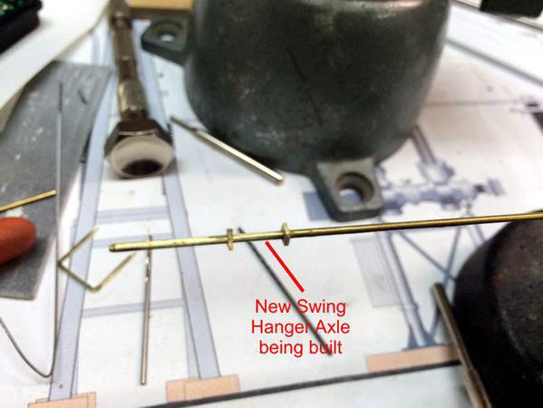
And here's the start of the new swing axle.


Swing Hanger Axle under construction


I'll solder those little plates to the 0.047" rod and then cut to length. All this stuff will be J-B Welded to the truck frame. I'll prime paint all the metal parts and paint them flat aluminum after assembling. If worse comes to worse I'll have to buy a new truck frame if they're available. It's not the first time a little job turns into a not-so-little job.


While I really like these Blombergs... they're beautiful and among the best renditions on anything out there. And I also appreciate that they're all die-cast parts, but they are much harder to repair, they're brittle, and make life miserable when they don't work the way you want.


The only reason I'm selling this beautiful A-B-B-A lash up is magna-traction. I wrote about this at length months ago, but I can give the executive summary. Magna-traction attracts the slightly magnetic roofing granules I'm using as ballast and gets into the drive gears stalling the engines and overheating their electronics. I can't use them on my railroad.

Attachments

Images (5)
  • HV Gantry 05
  • Undamaged Santa Fe B Truck
  • Damage to Santa Fe B Truck
  • Swing Hanger Parts
  • Swing Hanger Axle under construction

Went with my wife, daughter and the two grandsons to see "Interstellar" this afternoon so had less than an hour in the shop. In this hour I epoxied the concrete bases to the gantries,


HV Gantry 07


I then used the same epoxy to glue the bracket back onto the truck from which it detached.


Bracket Fix 05


I also used the RSU to solder the little rectangular pieces onto the swing axle shaft. It takes longer to type this than to fire up the RSU and solder the pieces. I measured the spacing with calipers.


Swing Axle Shaft Fix 04


I filed the ends to the correct length. I then fitted the swing hanger to the truck and it looks good. Unfortunately, just the pressure I put on the bracket to insert the hanger into the bracket that HADN"T broken,  broke it loose too. I'll epoxy that tomorrow. I prime painted the axle and swing arm. I'll probably work in the shop on Black Friday, since we're not going anywhere that day.


Swing Hanger fix 06


Even without the aluminum paint it looks pretty good. The swing hanger is not glued in this picture. I'll glue it in when I fix that loose bracket on the left.


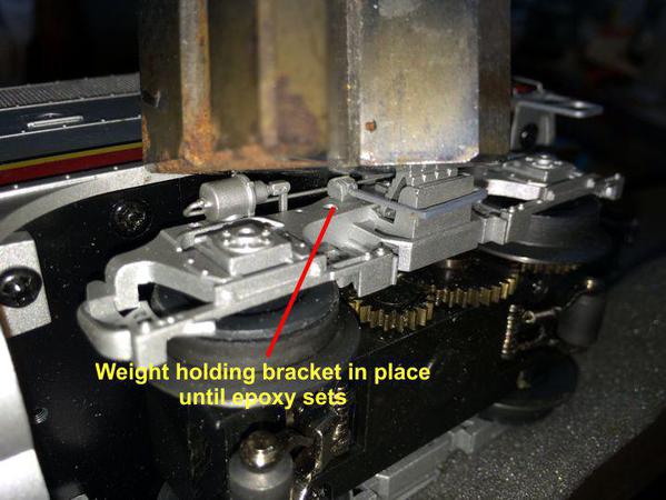
I was going to glue the second detached bracket tomorrow, but decided to do it tonight so it would be cured tomorrow and not delay finishing the job. I glued it on and added weight on top of it so it would bond in the right attitude.

 Bracket Fix 06


As for Interstellar... it was interesting, well acted, scientifically dubious, had an annoying sound track, and has a music volume that was so high that all of us, including the young ones, actually had to put our fingers in our ears. It was almost painful. I have a decibel meter loaded on my iPhone, but was reticent to take it out in the movie and turn it on. I would bet it was at least 105 db and probably higher. It detracted from a pretty good movie. I'd like to watch it at home on my system so i could adjust the volume to less harmful levels.

Attachments

Images (5)
  • HV Gantry 07
  • Bracket Fix 05
  • Swing Axle Shaft Fix 04
  • Swing Hanger fix 06
  • Bracket Fix 06
Last edited by Trainman2001
Originally Posted by Trainman2001:


As for Interstellar... it was interesting, well acted, scientifically dubious, had an annoying sound track, and has a music volume that was so high that all of us, including the young ones, actually had to put our fingers in our ears. It was almost painful. I have a decibel meter loaded on my iPhone, but was reticent to take it out in the movie and turn it on. I would bet it was at least 105 db and probably higher. It detracted from a pretty good movie. I'd like to watch it at home on my system so i could adjust the volume to less harmful levels.

I know what you mean.  My wife refuses to go to the cinema anymore because of the booming surround sound.  (I just remove my hearing aids and have mo problems at all!)


Anyway, we don't go to the cinema anymore - we wait and stream the movies on Amazon or one of the other services here at home.  Its a shame, I love to go to the movies, but the cinemas seem to think they have to give you something you can't get at home - like 200 decibels of teeth-rattling sound!


#2 grandson, commented last Saturday, when we were watching "Guardians of the Galaxy" on my big entertainment system the we don't have to go to the movies any more. In fact he said "that I don't go to movies any more!", completely forgetting that he, his mom, my wife and I went to the movies 2 weeks ago when we saw "Big Hero 6". His dad and #1 were in Chicago going to a Northwestern-Michigan game. The also got to the Museum of Science and Industry and he brought me back pictures of their vast HO layout.


Lot of topics to cover in today's report...


Finished the repair on the Santa Fe and it pretty much meets my expectations, but I'll leave that up to you guys. The new swing hanger is a little bit thicker than the original, but you have to pay attention to it to see it.


Truck Comparison


I made the 6 hanging insulators for the gantries, and then finished gantry assembly. I added NBW castings to the base plates, and applied Aero Gloss sanding sealer on all apparatus bases in preparation for concrete painting. Meanwhile, #1 grandson was working with me. First he was going to get into decaling the F-22 only to find that each and every decal was cracking and disintegrating. I tried to use the "Put fixative on the decals" method to prevent them from cracking, only to have them change color and become basically useless. These are the low-viz markings that are used on USAF stealth 6th Generation fighters. I now have to find new decals for the model. So... making lemonade, he went back to work putting down more ground cover on the layout. He then pulled another model off the shelf—a 1:350 Trumpeter Model of the USS Hornet including little models of B-25s that Doolittle used in the Tokyo Raid. He'll have fun with that one.


Here's the insulators. I turned little transition pieces to dress them up a bit.


HV Gantry 08


I then installed the cross members that connect the two gantry towers. These are butt-jointed to the towers and I added some little gussets to reinforce the joints. The cross members are 7.5" wide and clear the Disonnector by about 1/8" on each side.
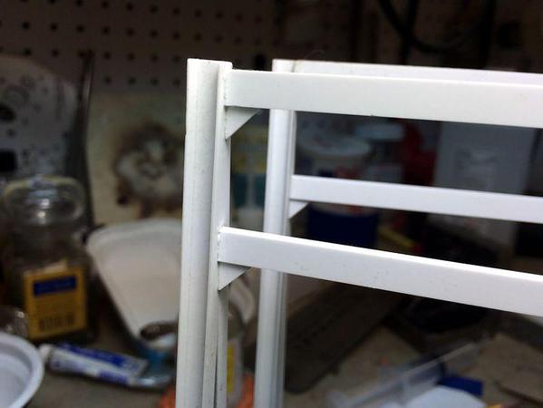
 

HV Gantry 09


Sanded the base plates to coincide with the "concrete" pads exactly. Then used the sanding sealer to seal the wood to improve finish for the acrylic "concrete" top coat. 


Measured and drilled the holes for the insulators in the bottom cross members. For the gantry over the disconnector used their spacing for the holes, but for the one that will sit over the breaker, used the spacing of the surge suppressors on the main transformer. Finally, I added True Details NBW castings. These are available in the hobby shop as are used for auto model detailing, but they're a nice size for larger 1:48 simulated fasteners. They're resin castings and can't be glued with solvent cement. You need to use CA.


HV Gantry 10


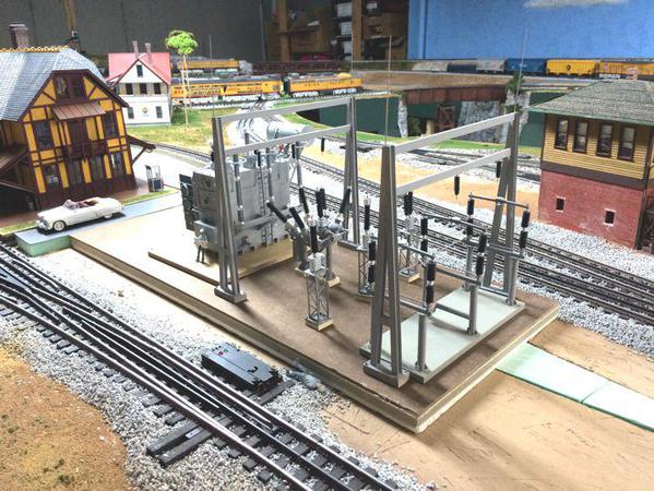
I ran out of time so didn't get a coat of paint on them, but I did set them down on the substation base to see how it looks. With these built, the HV section's apparatus is now complete. After painting, I'll add back the insulators. 


HV Gantry 11


This landscaping is either temporary, not quite finished or both, but we're are making progress covering the bare layout. The first is a retaining wall next to the station's access road. #2 grandson and I built it several weeks ago. #1 grandson painted it last weekend and I installed it with Titebond glue. Today I added back the ballast. It needs weeds, debris and other detritus that accumulates at the base of such a wall on an active railway. You can just see the substation base on the left.


Station Retaining Wall


Here's some grass down #1 applied to the long back run. I said temporary because I don't know the ultimate use for that territory, but it needed some dressing up.


More Grass


And finally, we're starting to do ground cover in the area around the switch tower. The idea is that there will be an unimproved road from the engine service area, across the five yard tracks and then leading to the switch tower with a small parking area. It needs more material, but that will wait until next time.
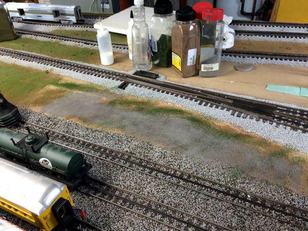
 

Switch Tower Access Road Construction


Whew! That covers today's work. I'm getting itchy to build the land forms around the substation base. This has to be done soon since I'm going to have to start fastening the apparatus to the base and finish the ground cover on that (fine gravel), and I don't want to be manhandling that very complex structure when attempting to do plastering and ground cover. I'm just not relishing getting back into the plaster business.

Attachments

Images (8)
  • Truck Comparison
  • HV Gantry 08
  • HV Gantry 09
  • HV Gantry 10
  • HV Gantry 11
  • Station Retaining Wall
  • More Grass
  • Switch Tower Access Road Construction
Last edited by Trainman2001

The gantries are finished. I almost forgot to put the lightening rods on them. I made them with a piece of 1/16" brass tubing with a piece of 032"wire soldered into it. I sharpened the rod to a point so lighting charges on my layout will be dissipated before they cause a strike. I then CA'd the to the corners of the H beams. With that it was ready for airbrushing. I proceeded to knock them on the floor and broke a base off on leg. After putting back on and a little touch-up paint it was good to go. The insulators are held with CA.


HV Gantry 12

HV Gantry 13


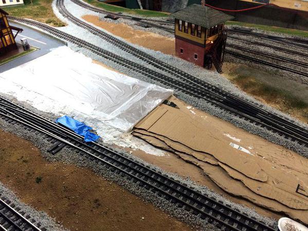
I realized at this point that I was going to have to get sloppy with some Scuptamold. Before I can start installing any high voltage bus wiring, I'm going to have to prepare the base to permanently mount the equipment. I can't do this until the site is prepared. So I removed all the stuff that was being displayed, took the base and covered it front and back with Stretch and Seal, and then started plastering it into place. I also built a little topo using layered cardboard stapled to the OSB. This went much faster than using cut Masonite like was done on the other side of the train station. 


Here's the plaster work started on the board and showing the cardboard elevation pieces.


SS Base Prep 01


Shortly after this was taken, it was all plastered. I'm definitely getting better at this...


SS Base Prep 02


I wanted to pull the base board before the plaster fully hardened. This is the first time I used this method which was brought to me by Ashe Rawls from Richmond, VA. He admonished me to never permanently glue buildings into the layout since you may have to remove them for service, or if you want to sell them. He wraps the base with Saran Wrap and plasters right up to the edge. Then he is able to make a socket for the building. He used light landscaping to hide the seam so you never know that the buildings aren't permanently planted. I especially wanted to do this for the substation.


To pull it I screwed and eyebolt into the Masonite top surface and gave it a tug. It came out but the strip of plaster on the near side did break loose from the platform. It went back to position and if it's loose I glue it in place with either hot glue or white glue. Shouldn't be a problem.


SS Base Prep 03


It takes several days for Scultpamold to fully cure. The plaster sets in 30 minutes, but the fiber filler takes a long time to fully dry out and I don't want to paint or landscape until it does. Meanwhile, I'm now starting on getting the base fully detailed.


I mixed some "concrete" acrylic and hand painted the bases of all the finished equipment. Tomorrow is going to be poor weather again. Goody! More shop time without a guilty conscience.


SS Base Prep 04


BTW: I did order Brennan's Chain Link Fencing. I'm asking Dennis about how to add barbed wire extensions to the fence top since many electrical installations have it to keep silly people out. If there are any ideas out there on how to do this, I'm listening. I'm figuring a couple more months work on this project. I have others waiting in the wings... lots of them.

Attachments

Images (6)
  • HV Gantry 12
  • HV Gantry 13
  • SS Base Prep 01
  • SS Base Prep 02
  • SS Base Prep 03
  • SS Base Prep 04

If you are buying fence rather than scratchbuilding, several suppliers sell barbed-wire. There are some links in this thread:


https://ogrforum.ogaugerr.com/topic/barb-wire-fence


If you prefer to scratchbuild, here is one way to make barbed wire:


Barbed Wire


Some people simply wrap thin wire around a nail to form barbed wire coils.  The barbs aren't there, but they are pretty tiny in O-scale.

 I looked at the barbed wire videos. It certainly seems easy enough to do, although tedious and somewhat dangerous since you're actually making metal barbs. Dennis Brennan also suggested using plastic screening cut down the lines leaving little barbs. He says they can be attached to the fence tops with shipbuilding eyebolts. i have some of those. I'm not sure I'm going to add them, but at least I know there are options. 


Plaster was drying well and will be fully cured in a day or so. I worked more on the base plate, laying out where everything will go and then cut the concrete pad for the control room. 


Using a Sharpie, I laid out the center lines of all the equipment.

 SS Base Prep 05


Based on the design, the foundation for the control room intersects with the transformer's concrete pad. Again, I'm making a sandwich of two layers of Masonite. I ran out of enough of that wonderful German stuff so there's a layer of old, not-so-hot, pressed board glued to one piece of the German hardboard.


 SS Base Prep 06

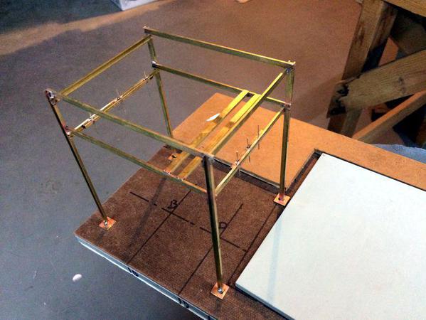
I then started working on the intermediate voltage gantries. I didn't have styrene small enough in cross section to do what I wanted, but I did have brass. So using brass channel of two different sizes I started construction. I really want to get all the apparatus on the secondary side completed too before I attach anything to the base and do the gravel ground cover.
 

Here's a SketchUp drawing of the gantry.


Intermediate Voltage Gantry0015


Insulators will be hung from additional brass pieces soldered to the shorter cross members.


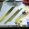
I used the razor saw and miter box to cut the pieces to their three lengths. I use a block clamped to the work bench as a bench stop to cut multiple pieces. I also cut four square 0.032" brass plates that will be soldered to the bottoms of each leg. I'm finding that using the TapMatic brass cutting fluid works like a charm on all the hand operations I'm doing. This includes using the razor saw, drilling with small jeweler's drills and using the jeweler's saw. It just makes the cuts smooth without any binding or grabbing.


IV Gantry 01


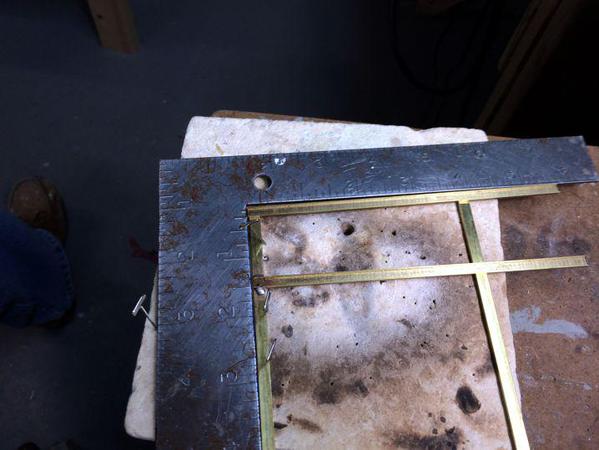
This is another great chance to use the resistance soldering unit. I'm starting using a higher melting point soldering to solder the longitudinal cross-members. I'm soldering on the ceramic soldering pad. It handles high heat and also is easy to hold things with "T" pins.


IV Gantry 02


I set the heat range to 80%. The brass has a lot of mass so it took a few seconds to heat high enough to melt the silver bearing, non-lead, plumber's solder. I'm using the old square to hold things at 90º.


For the inside corners I'm using V-blocks. I also am using the TIX liquid flux. It works for all of the solders that I have. I cut a small piece of solder, place it next to the joint with a pair of tweezers, and then clamp on the RSU. As soon as the solder flows into the joint I release the foot switch and hold the RSU in place.


IV Gantry 03


Even with my precautions, I was unhappily surprised that one of the two sets was not in square. So I reheated and separated the offending pieces and will re-solder it tomorrow.


IV Gantry 04


The one on top is the good one.


Tomorrow, I'll be assembling them into a square structure. The TIX solder melts almost 100º lower than the solder I used for this step so it shouldn't de-solder the previous joints. At least that's the theory.


I don't know what's going on with the picture handling engine on this site. Almost every picture I posted was turned in a way that was not on the original image. I shot them all with my iPhone, all were shot landscape and all with the phone in the same orientation. I didn't crop any in my Corel PhotoPaint, just fixed contrast and re-sized, but yet the pictures are turned. I know I've carped about this before, but today it was particularly annoying. Am I the only one that has this problem?

Attachments

Images (7)
  • Intermediate Voltage Gantry0015
  • IV Gantry 01
  • SS Base Prep 05
  • SS Base Prep 06
  • IV Gantry 02
  • IV Gantry 03
  • IV Gantry 04

I'm wearing out the word "Wow!."  But, Wow!


With regard to the barbed wire.  Why make the barbs?  At 1:48 they will be about 1/100 of an inch long, and about 2.5/1000th inch wide.  You would have to have your eye within  a few inches to see them.  I'd leave them off.  Safer and more comfortable to work with.  You still need really fine wire.  

Trainman - I took a second look at your posting and saw your comments about the image handling on the forum turning them around, etc.  It can be frustrating but there are small inconsistencies in software from cameras, phones, and systems that creates these and other problems (I had one with contrast for a while).  I solved nearly all of these by a "trick" that takes a bit but ultimately saves time.  Regardless of which of three cameras or phone I take the photo from, I copy and paste the pictures into MS Powerpoint, arrange them covering each page  like I want, and then "save as" the presentation as a JPEG file(s).  Powerpoint creates a folder with a jpeg of every image (only the part covering the slide, cutting it off at the edges).  It also compacst the files (from perhaps 6 Mb to 100 kB! so they now load onto the forum so much faster) and whatever else it does, I never have problems with them now.  It's a pain to do but I do it most of the time and my inversion and contrast problems have all ended. 

Lee, thanks for the tip! I'm loathe to go through another step in this process since I'm already bringing the images into Corel PhotoPaint to adjust color and resample to a lower bit count. I've actually spoofed the system by rotating the pics in Windows file viewer, and then rotating them back. For some reason this resets the image to its original format.


I had only minutes in the shop yesterday so I re-soldered the non-square cross member. Today, I'm going to finish them up. I also found the medium voltage breaker to use. It's ABB, nice and compact, and rectangular (since it's easier to produce in styrene).


Vacuum interrupters 2


As usual, I was able to pull a full set of prints for it.


MV Breaker 2


I also need to find a medium voltage, outdoor disconnector which would complete the apparatus for the entire station.

Attachments

Images (2)
  • Vacuum interrupters 2
  • MV Breaker 2

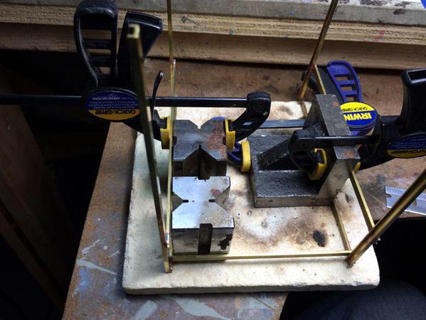
Compared to the size of the HV stuff, the medium voltage equipment is puny. I finished soldering together the MV gantry. It went together nicely again as the direct result of the RSU's capability. Here's the fixturing I used to ensure that it came out reasonably plumb and square.


MV Gantry 05


The small Irwin quick clamps are very handy and I use them all the time. It's also important to have supply of square edged things. I have two V-blocks, 2 small angle plates and one larger one, and I could use more.


To mount the insulators I soldered some 1/8 square brass tube into the channel. Before soldering it in place, I laid out and drilled holes for the insulators. One set is spaced to match that of the secondary output bushings on the main transformer, and the other set reflects the spacing on MV breaker I'm going to model.

 MV Gantry 06


MV disconnects are almost exactly the same as the fused disconnects I made for the telephone poles (now) many months ago. They are also small and inconspicuous compared to the large switch I had to build for the HV side. To hold these switches in the gantry I soldered two more cross members. I coped the ends of these channels so they nested into the side rails.


I also soldered some 0.032" brass rod into the insulator holes. Since I'm dealing with brass into brass, I decided to solder these rods. In the rest of the construction I usually CA'd them in. Soldering is much more secure, but I couldn't do this AFTER the plastic sheds were added to the brass rod since it would melt. So here's the completed gantry.


MV Gantry 08


In staring at this picture I realized that I soldered the switch support bars on the wrong side of the gantry. In this image, the gantry is turned around. The insulator pins with the wide spacing goes next the transformer pad and the side with the narrowly spaced insulator pins goes on the left side. The support bars should be on the gantry's transformer side. I will de-soldered and move them tomorrow. I suppose the switches could reside above the breaker... hmmmm.


This was actually the first fully-brass construction I ever made. The brass shapes were bought years ago in anticipation of making something from brass. It all had to wait until I bought the RSU and had the right project. I'm now feeling my oats and will probably try to build my own signal towers. The RSU will also be very helpful building the Brennan chain link fence. i got a great deal of satisfaction building this.

Attachments

Images (3)
  • MV Gantry 05
  • MV Gantry 06
  • MV Gantry 08

The gantry looks great!  I do agree now that you mention it the proper placement of the support bars should be moved.  Actually, I probably wouldn't even notice.  


I can send my daughter's hamster with running wheel down to Kentucky, so you can hook it up for generation.  I have joked before the since some of those critters run all night, they could generate a nice amount of electricity.  

The gantry was fixed so the cross bars are now on the correct end. I also made the concrete pads for the gantry and the circuit breaker. The CB is also completely out of brass. But you can't see it. Reason? My HP dv6 laptop blew up today. I'm writing this on my wife's iPad Mini and don't have any pics loaded. 


The laptop is about four years old and was on almost continuously for that time. a couple of weeks ago the fan started making noise. It kept getting louder. My son had a similar HP and his flan died also. He said it sounded like an old window air conditioner. Very apt description. Then software starting running weird, especially CPU and video intensive ones like SketchUp. Tools would freeze or the mouse would stop working. I did research yesterday to see about cleaning the fan. A pain in the butt! You have to disembowel the entire computer to get to it. And you need special thermal transfer paste specific to HP (according to Intel) For the heat pipe connection to the main chips. 


Then today when I came up from the shop, my computer had stopped with a bios message saying the fan had ceased operation and continuing to use would cause severe damage. I'm now in the market for a new machine. My wife, bLess her heart, thinks I should finally make the switch to Mac.  In fact she thinks I should get a MacBook Pro like my son has.  One must always do what one's spouse wants. My daughter in law is a Mac maven and suggests getting a refurbished one. They're 400 dollars cheaper. I'll keep you all posted on what's going on. 


Meanwhile, the brass circuit breaker box came out pretty good. I'll try uploading the pics to the cloud and getting them to this a Mini and put them on another post.  


I figured out how to load the pics 


Attachments

Images (3)
  • image
  • image
  • image
Last edited by Trainman2001

Well fans, it didn't take long before i was up and running with a new laptop. I sprung for a big one, the MacBook Pro with the 512GB solid state main drive, and Intel i7 250 ghz cpu it's a quad core monster that does SketchUp like butter. In fact, in just a small test I realized how awful the other machine was getting. It was struggling mightily in running SketchUp.


I didn't work in the shop today, but I did get some stuff done yesterday. I had added the concrete pads the day before and they were fully cured, I added some more details to the breaker and then rattle-can sprayed them Krylon primer gray. Tomorrow I'll airbrush the lighter gray and add the insulators. These will then be done leaving just one more detail; the mechanical disconnects that will go up into the gantry. In looking at the base, I'm beginning to think that instead of a brick control building which is overkill, I'm going to leave the concrete bare as a place to bring in service vehicles through the gate that will be at that corner.


I added the small rear door and turned and soldered the bushing transition pieces. The RSU really made this assembly possible. My challenge in working with sheet brass is not having the sophisticated sheet metal tools like shears and brakes. When you cut this stuff with tin snips, it tends to curl up and then it gets kind of beat up when flattening it again. I would have like to have made the body with just one piece folded, instead I had to solder individual plates to small interior angle pieces.

IMG_2653


Here's one view in primer

IMG_2654

IMG_2655


And the other. I used some filler on the seams before the final coat. The lever on the left side is the manual trip lever which I'm going to paint bright red.


The fencing came from Brennan and that will be up after I make the disconnects. Onward and upward.


Now all i have to do is retrieve the myriad of files from the hard drive i removed from my old computer. The drive was okay and my daughter in law sent me an enclosure to turn it into a auxiliary drive. But... I can't find my data on it. i can find all the program files, windows files etc, but nothing that looks like the several thousand files that represent all the work that I've done. If anyone out there knows how Windows encodes the User data files, please let me know.


Apple said I may have to load Windows and run it using the Boot Camp utility. But there's a rub. You have to obtain a native Windows 7 or 8 ISO file, and then obtain the Windows install utility that was used when they loaded it in the HP originally. Needless to say, both of these requirements are messing with my head.


But the computer is very cool!

Attachments

Images (4)
  • IMG_2651
  • IMG_2653
  • IMG_2654
  • IMG_2655

Fantastic unit Trainman2001.  I love to study how you make things.  Very interesting.


And it looks really nice. 


Interesting about the paint. For about fifteen years from 1994 until 2010, I didpart time duties as Series Editor of the Power Engineering series of books for Francis and Taylor (CRC). It didn't pay much but it forced me to read copious numbers of power engineering books which kept me up to date, and I got free copies of all CRC technical books . . . Anyway, they came to me and asked what colors I recommended to give a common look to the covers of all the books in power engineering.  I gave them the panatone colors used to paint electrical equipment, the sky gray and dark green.  So my eight books, plus many, many others in power engineering published during that period were all were done up in the colors you, and the manufacturers, are using for your equipment. 


DSCN0706

Attachments

Images (1)
  • DSCN0706

It is amazing the difference in speed when one gets a new computer.  Sounds like you got a good one.  I too find it very strange that you can see the program and operating system files.  Did you put them in My Documents folder?  Maybe a hidden setting is selected.  Why, I wouldn't know.


On to the breaker.  It looks very good once again.  As far as not being exactly smooth, it gives the impression of a workhorse that has seen some bumps while being moved, and a few sloppy coats of paints over the years.  Yes, those things sure can happen when the substation guys get hold of some equipment.  

I've uploaded 35,000 pictures and then spent the rest of the time culling them down to a mere 16,000. Some years ago, my son in law had asked me to back up his pics on my computer. Those pics have been reproduced in each new box I've owned. I've now removed them. There were also many duplicated rolls. I've kept all the important ones.


A good example of the performance different between this machine and my last. When I was rendering the Bernheim distillery image from SketchUp it took 35 minutes on the old one. It took 5 SECONDS ON THE NEW ONE. That's correct... 5 seconds. Almost instantaneous. Programs load in a blink. All I can say is magnetic hard drives are dead, long live magnetic hard drives. Moving the files from one computer to the other was an ordeal, but it was worth it. It was the main reason why I didn't want to change regardless of how badly the other one was running. But the breakdown forced my hand and I'm not complaining.


Back to the topic...


I'm making the MV disconnects. Like some of the other components are like jewelry making. I'm using little channels for the bases and bending (and drilling) the thin stock from PE frets. They're almost "operational", but that really doesn't matter. It's all about appearances. 


Here's the little brackets soldered to the base channel.


IMG_2658Th

This was my second attempt. The sloppy solder job was due to the middle bracket de-soldering when I was putting in the last one. I was using TIX solder with melts under 300 degrees. Once TIX joints come loose, it seems very hard to re-solder them and things get messy. I started using a very fine diameter electronics solder for the remaining units.


I drilled the first center bracket when it was off the base, but found this to be very awkward and difficult to center all three holes. 


IMG_2657


All the rest I soldered first then drilled.


For the moving contact, there is a bar attached to one of the ends that lifted and moved away from the fixed contact by motion of the middle swinging insulator. I had to drill a 0.032" hole in the center of a 0.048" square brass rod. Like I said, Jewelry Making. By carefully getting the punch mark dead-center in the brass enables the drill to drill the hole and still leave some wall thickness at the edges.


IMG_2659


The bracket to which it's attached also has three holes; one clear through for the pivot and then one in the middle where I soldered the mounting pin. Jewelry making!


Here's the unit assembled. (one of three...one for each phase)


IMG_2662


And lastly, here's the disconnect just sitting on the gantry's cross bar. I was going to try to screw them on and attempted to make some #10 Jeweler's screws. I machined some blanks that were .033" in diameter, cut the threads with the Jeweler's die plate i recently bought, and then used a small drill for the tap drill size and cut threads with the #10mm tap. It worked...sort of. But they stripped very easily. I tried twice and then decided to epoxy the disconnectors to the gantry.


IMG_2663


Since taking this pic I also built one more with one to go. Once they're built I'll hand paint the base leaving the brass bare. I'll also air brush the gantry and MV breaker sky gray and with that, all the apparatus will be built and it will be onto the chain link fence kit. I still have to build lights and a small control enclosure. Like I noted before, I'm not going to construct a large control building since I want to leave some parking space inside the fence.

Attachments

Images (5)
  • IMG_2658
  • IMG_2657
  • IMG_2659
  • IMG_2662
  • IMG_2663

Add Reply

Post

OGR Publishing, Inc., 1310 Eastside Centre Ct, Suite 6, Mountain Home, AR 72653
800-980-OGRR (6477)
www.ogaugerr.com

×
×
×
×
Link copied to your clipboard.
×
×