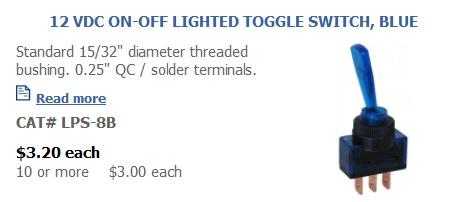
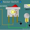
Hey Guys, I'm looking for some advice on these SPDT switches.

https://www.amazon.com/Ulincos...keywords=spdt+switch

I haven't purchased any yet. I was thinking of using them to power on/off sidings and about four yard leads instead of using the standard toggle switches. I am by no means an electrical expert but I have hooked up SPDT switches before but not illuminated switches. I see the LED has different power requirements. Since this is on a layout, how would you provide the power for the LED's? What would you use? I'm not 100% sold on these yet so if someone has a better idea or a better option please share. Thanks

Original Post

Replies sorted oldest to newest

Like your pushbutton switch, these toggles also would need a separate power supply for the lamps.

The common connection is for the load(hot - center rail power) and the lamp 12 volt(-), the center terminal is for the switched load(can be AC or DC, center rail AC in your case), and the 12v terminal is for the +12 volts for the lamp.

Two isolated power supplies, in the case of a train layout, can share a common connection even if one is AC & the other is DC.

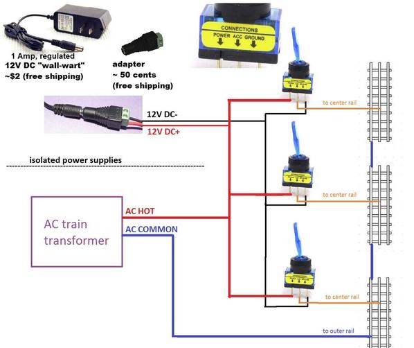
Like Rob says, if you have an isolated power supply such as a "wall-wart" DC adapter you can use the 3-terminal illuminated automotive switches.  I found this image which looks like the same low-cost blue switch with the typical automotive terminal assignment.  Note though that in the 1 customer review for that switch, the reviewer says the blue bat handle itself does not light up which is not what you'd think.  Anyway, here's how you might wire up a few sidings or yard blocks with two isolated power supplies...one being a 12V DC wall-wart to power a 12V bulb (LED) built-into the automotive switch.

on off isolated switches

A switch will illuminate when AC track power is applied to the respective siding. 


Attachments

Images (1)
  • on off isolated switches

Great explanation. I got into trouble wiring the ground terminal to AC ground, because in the off position the switch connects the ACC and Ground terminals. The light worked, but when an engine spanned a siding that wasn't powered it was a direct short. Will this not work if you are already sharing grounds with the two power supplies, as in building lights?

I had the same problem as John H above with some led lighted switches, different a type than shown here. I used all track voltage and all was well until a year or so later. The siding was always on when the train parked there was running so no problem. Then I set a switch wrong one day, it went to an unpowered siding, and that's when I discovered the problem. Took a while to figure it out, but it was the switch. I had some relays and that was a quick fix.

At the time I didn't know about mixing the AC and DC, but Stan has since explained that to me a few times and I am finally catching on. I think I may now change to Stan's wiring above, I could get my relays back and it does look more elegant and has less wiring and less parts involved.  

Edit: PLCProf posted while I was typing and after reading his post I think I still see the problem. I missed it the first time I looked. Guess the relays will remain. Drat!

Mine are marked Supply, Load and Earth. Load and Earth light the LED and they are connected when in the off position. These are rocker switches, 10 amp, red LEDs and ebay specials from the Far East.

Last edited by rtr12
PLCProf posted:
 

Actually, this doesn't work.

Many of these switches (photo attached) are actually SPDT switches. The lamp is connected between the ACC and GROUND terminals. When the switch is in the OFF position, the ACC and GROUND terminals are connected.

Well that's a wet blanket to say the least!  When you say "many of these switches" are there 3-terminal illuminated 12V automotive switches that are not SPDT switches (i.e., just SPST switches)?

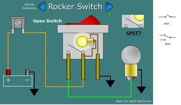
Here's a diagram I had looked at which kind-of-sort-of suggests an illuminated automotive switch which does not "short" the bulb when the switch is off; the symbol for the switch appears to be of the SPST type and that the bulb "ground" is an isolated terminal independent from the on-off switching function (?):

spst or spdt

Anyway from the diagram of the OP's original illuminated switch it appears it is a 5-terminal switch with the lamp (LED) on its own 2 terminals...and the 3 other terminals are an independent SPDT switch.  If that's the case then the idea (issues identified by PLCProf) of simultaneously switching hot-AC and 12V DC+ (assuming they are isolated supplies) to illuminate the switch when thrown would apply.


Attachments

Images (1)
  • spst or spdt
Last edited by stan2004
Jameszz posted:

..What would you use? I'm not 100% sold on these yet so if someone has a better idea or a better option please share.

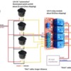
So my conclusion from the on-going discussion is these 12V illuminated switches are really meant to switch 12V DC.  Trying to mix AC and DC with isolated supplies is a non-starter (unless I've misunderstood Rob's idea).  So taking rtr12's post about using relays in conjunction with these attractively priced switches, here's another option.  Automotive switches with LEDs are about $1-2 on eBay, free-shipping, many styles, many LED colors.  12V relay modules are about $1/relay and come in modules of 1,2,4,8,16...

4 switches 4 relays less than 10 bucks

So in the case of the 4 yard blocks, you need 4 illuminated switches, a 4-relay module, and a 12V DC wall-wart.  Total cost about $10 on eBay (free shipping).  So each 12V switch would only switch 12V DC and drive one channel of the relay module.  A relay (10 Amp contacts) would switch the track voltage AC to the respective yard block.
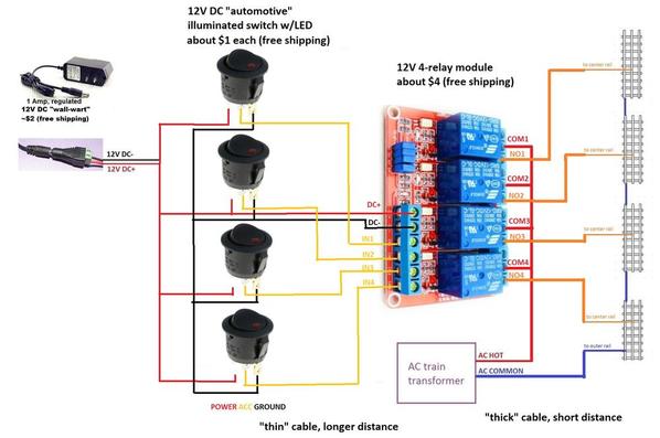
4 switches 4 relays hookup

In some layouts, the control panel might be some distance from the controlled blocks.  Note that with this configuration, the 12V DC control signals thru the toggle switches is low-current so the cabling can be "thin" wire.  The AC power itself is high-current by placing the relay module near the controlled blocks, the amount of "thick" cable is minimized.  In the non-relay method, "thick" cabling must be run from the control panel to the controlled blocks.


Attachments

Images (2)
  • 4 switches 4 relays less than 10 bucks
  • 4 switches 4 relays hookup

Add Reply

Post

OGR Publishing, Inc., 1310 Eastside Centre Ct, Suite 6, Mountain Home, AR 72653
800-980-OGRR (6477)
www.ogaugerr.com

×
×
×
×
Link copied to your clipboard.
×
×