Hello everyone, Happy Memorial Day and I thank all of the men and women who serve and who have served to protect our country.


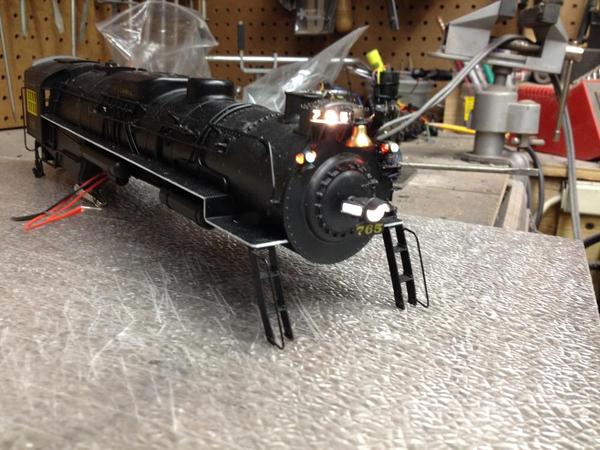
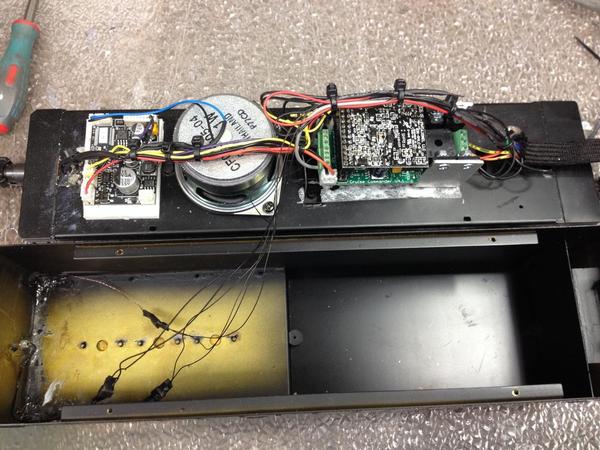
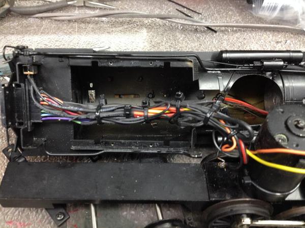
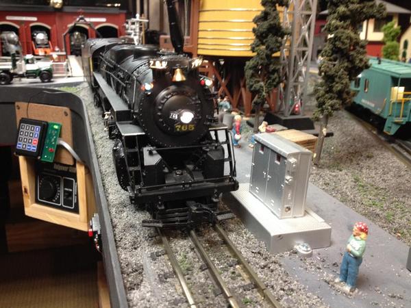
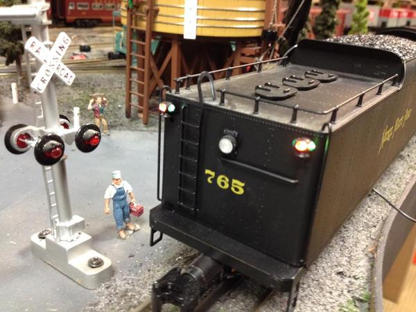
        This is a Right-of-way-industries conventional brass 765 Berkshire, it has been fully upgraded with ERR, a fan driven smoke unit, and full LED lighting. There's a total of eight LED's between the engine and tender, there's a massive amount of wiring that went into this upgrade, the tether from the engine to the tender has eight pins. This was a huge task, but as always I enjoyed every minute of it, the number board's, all marker's, headlight, and tender light are all LED's.


         The fan driven smoke unit will eventually be synchronized with the chuff, so it will also have 4 puffs per revolution.

You will notice in the video a wire hanging out of the bottom of the tender, this is the antenna for the ERR unit. It will be neatly installed under the bottom of the tender, the reason for this is because this entire engine and tender are brass, and if the antenna is left inside the tender, you won't have any command control over the engine. What's amazing to me is how smooth this can motor run's, notice the can motor has no flywheel, this unit is from around 1991.  Here's a few pictures and a short video of this engine in action.


Captain John, I hope you like the way it turned out!!!!!!!


Thanks for looking,

Alex


trains 3979

trains 3980

trains 3981

trains 3982

trains 3983

trains 3984

trains 3985

Attachments

Images (7)
  • trains 3979
  • trains 3980
  • trains 3981
  • trains 3982
  • trains 3983
  • trains 3984
  • trains 3985
Last edited by Alex M
Original Post

Replies sorted oldest to newest

Thanks Brian, John, Don, Harry, Steve, Dave, and Alan for the great comment's


Steve, you'll love the way they turn out


Gunrunner John, Yes I received it today, can't wait to try it out.


Alan, I wish that would happen someday !!!!


Marty, being the engine is all brass, I installed the antenna on the underside of the tender.


Richard, I really don't know how I fine the time lol. But I love doing it .


Steve thanks, your Army loco is the perfect loco to run this weekend, enjoy it


I thank you all,

Alex

Last edited by Alex M

I have not tried the under-frame-antenna mount yet; I always use the tender shell - unless I'm lucky enough to have a plastic coal load to use. I'll try it next time; the

modern die-cast non-TMCC/ERR locos usually have screws that can be easily replaced with nylons, and I use a thick-ish tape (not so thick as to be visible), but the

brass tenders seem to require drilling and tapping for the larger screws. I do it, but it's

tedious.


What method do you use to "float" the antenna under the frame?


Hi Marker, and D500, I thank you for your interest and input.


Marker, with ERR the chuff is triggered with magnets and a reed switch, the reed switch  wires now go directly to the ERR sound board.


D500, I will post photo's when I do the final install on the antenna wire, this way you can get a good view. With this type of tender, it would have been **** to isolate the tender from the chassis. Meaning a lot of work, So far I have a great signal. I hope it stays like that.


Thanks,

Alex

Very well done.  Those were built way before TMCC so there was no thought to where the wires went. 


A few questions:
what type of LED did you use for the  marker lights (and did you have to make a separate supply to power them)?

WHy didn't you use the cam switch in the loco?  It is 4 chuffs/rev.  The way TMCC is wired you should only have to diode  isolate it.
 
Regards,

Lou N


Originally Posted by Alex M:

Hi Marker, and D500, I thank you for your interest and input.


Marker, with ERR the chuff is triggered with magnets and a reed switch, the reed switch  wires now go directly to the ERR sound board.


D500, I will post photo's when I do the final install on the antenna wire, this way you can get a good view. With this type of tender, it would have been **** to isolate the tender from the chassis. Meaning a lot of work, So far I have a great signal. I hope it stays like that.


Thanks,

Alex


Originally Posted by Lou N:
Very well done.  Those were built way before TMCC so there was no thought to where the wires went. 


A few questions:
what type of LED did you use for the  marker lights (and did you have to make a separate supply to power them)?

WHy didn't you use the cam switch in the loco?  It is 4 chuffs/rev.  The way TMCC is wired you should only have to diode  isolate it.
 
Regards,

Lou N


Originally Posted by Alex M:

Hi Marker, and D500, I thank you for your interest and input.


Marker, with ERR the chuff is triggered with magnets and a reed switch, the reed switch  wires now go directly to the ERR sound board.


D500, I will post photo's when I do the final install on the antenna wire, this way you can get a good view. With this type of tender, it would have been **** to isolate the tender from the chassis. Meaning a lot of work, So far I have a great signal. I hope it stays like that.


Thanks,

Alex


Hi Lou, thank you for the nice comments.


Lou no separate power supply needed,I use Evan's design's Pico LED's that can handle

8 to 19 volts. They hook up to standard track power, and they are super bright warm

white LED's. They are fantastic.


Lou, I didn't use the Cam switch because, I didn't have anymore room in the wired tether that goes from the engine to the tender. The tender has all the ERR installed in it. My tether was already 8 pins. It was much easier just to use the reed switch with magnets on the tender wheel.


Thanks,

Alex

Thank you for that information.  I'll have a look at those LED's.
 
I can truly appreciate your work; in the days of TAS Phil would curse my name when he had a ROW upgrade.
 
I still have not upgraded any of my ROW equipment.  I will probably start with the PA's first.
 
Too bad about the 8 pin connector.  I thought i was going too far wiith 8 pins back then. 
 
Regards,
 
Lou N
 
Originally Posted by Alex M:
Originally Posted by Lou N:
Very well done.  Those were built way before TMCC so there was no thought to where the wires went. 


A few questions:
what type of LED did you use for the  marker lights (and did you have to make a separate supply to power them)?

WHy didn't you use the cam switch in the loco?  It is 4 chuffs/rev.  The way TMCC is wired you should only have to diode  isolate it.
 
Regards,

Lou N


Hi Lou, thank you for the nice comments.


Lou no separate power supply needed,I use Evan's design's Pico LED's that can handle

8 to 19 volts. They hook up to standard track power, and they are super bright warm

white LED's. They are fantastic.


Lou, I didn't use the Cam switch because, I didn't have anymore room in the wired tether that goes from the engine to the tender. The tender has all the ERR installed in it. My tether was already 8 pins. It was much easier just to use the reed switch with magnets on the tender wheel.


Thanks,

Alex


Post

OGR Publishing, Inc., 1310 Eastside Centre Ct, Suite 6, Mountain Home, AR 72653
800-980-OGRR (6477)
www.ogaugerr.com

×
×
×
×
Link copied to your clipboard.
×
×