I've been looking at the communications between the R2LC and RailSounds board in hopes of building a little board that will interface and capture the events like horn, bell, couplers, direction changes, etc.  This will feed into a uP based board and allow triggering other actions from each of these activities.


I am looking at the actual command formats, and it appears that they an 8 bit serial byte with a zero start bit and a one stop bit.  The odd thing is they appear to be at about 3,000 BPS, certainly an odd speed. This is coming from an ERR Cruise Commander, since the lead is easy to get to.


Here are some shots of serial data for various commands.  I am able to see where the command is proper, so I'm pretty sure I'm looking at this right.


Am I missing something basic here?  Has anyone else looked at these for similar purposes?


Bell Command


Bell


Front Coupler Open Command


Front Coupler


Rear Coupler Open Command


Rear Coupler

Attachments

Images (3)
  • Bell
  • Front Coupler
  • Rear Coupler
Original Post

Replies sorted oldest to newest

Originally Posted by N.Q.D.Y.:

I may be wrong in my thinking, but if you have 8 data bits, one start bit and one stop bit, that would give you 300 bytes per second after ignoring the start & stop bits. Which equates to a standard baud rate of 2400bps. Or am I thinking too simplistically here?

2400 baud would be 2400 samples per second, or .417 milliseconds per bit.  I'm seeing 9 bits pretty exactly in 3 milliseconds, which is .333 miliseconds per bit, or 3000 baud.  Baud (or more correctly the modern term BPS) refers to the actual bit rate, including any start and stop bits. 


BAUD refers to the number of changes in the signal, not the actual bit rate.  There are some modulation schemes like QAM that transmit multiple bits for one BAUD, for instance.  As it turns out, when talking about digital one's and zero's, with binary digital encoding, baud and BPS are the same.


Originally Posted by DaveJfr0:

Nice screenshots. The serial line is only 2.5VDC?


I want to do something similar, but I don't have access to an o-scope.  I would try to check a regular R2LC and see if the frequency is different.


I'm not sure what other ones you did, but I'd be interested to see several captures, especially to see what the AUX1 button does to the signal…:


AUX1+0

AUX1+1

AUX1+3

AUX1+4

AUX1+5

AUX1+6

AUX1+BOOST

5 button; NO AUX


My end goal is to make a DCC decoder that acts as a R2LC and provides input to a RS chip.  


My first project car would not yet drive motors, so not worried about that yet, but it would be neat to make a swappable board with the R2LC that makes a Lionel loco that swaps the TMCC for DCC…just need to make a board that accepts DCC input and can interface with what the R2LC currently sends out to its RS and motor boards…


Sounds like a good project.  As far as the amplitude of the signal, that is the signal that comes right out of the R2LC, it just goes through a trace on the ERR Cruise Commander to the RS4 board set.


As far as the commands, have you looked at the The complete guide to command control - Lionel, it details all the commands.  The page below is where I got the command structure from, and as you can see, it lines up exactly with the three commands I sent and what I saw.  The Alt+0 button, for instance, would send the ALT1 command from the table below and then the numeric command for 0, i.e. 00010000 with a low start bit and a high stop bit.  Note that a leading zero is not in the table, and also the bits come out LSB first on the serial link.


The screenshots are from an ATTEN ADC1102CAL digital 'scope, a recent acquisition for doing projects like this.  I got tired of trying to see this stuff on an analog 'scope.
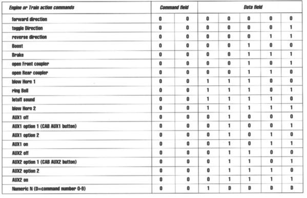


TMCC RS4 Command Packet

Attachments

Images (1)
  • TMCC RS4 Command Packet

I thought the coses were published someware. Be advised that the Legacy R4LC board outputs 9 bits in a Legacy invironment. Either board also has several outputs that are of an on/off nature for such things as the Smoke generator and lights and a pulse Length modulated (PLM) signal to control the motor speed and direction. The signal on the dataline for the coupler only serves to trigger the coupler sounds in the sound system, the couplers are controlled by one of the on/off outputs for all but the tender coupler.


Al


First off, I'm not looking at Legacy, since that is a patent issue, and I couldn't sell or distribute anything based on decoding the Legacy.  I could decode Legacy for my private use, and at some point I might consider it.


I realize that this is not the actual control outputs, but if I key on the sound command, I get the same effect for detecting remote button presses.  As far as stuff like the PWM signal for speed, I'm just looking at the data going to the RailSounds board to trigger sounds, I'm not worried about decoding PWM streams, though that is pretty trivial if I were to consider that in the future.


The purpose of this project is to intercept the commands to the RailSounds board and trigger events based on the commands issued to the command content.


What are coses?

I didn't get it, sorry Al.   I was wondering if it was a new engineering term.  I'm not sure where you were stepping on toes, if I conveyed that message, it was in error.


As far as the codes, I posted the page from the manual where they're listed.  I'm interested in the exact bit rate, it appears to be about 3000 BPS, but that seems an odd choice.  I think the actual command codes make sense, I was able to see how they correlate with the stuff I was capturing.  Interesting that the output to the RailSounds board is only the actual command byte, and not the first byte of the format.


Last edited by gunrunnerjohn

As I stated in a post on another similar thread I've done many projects decoding the serial data. For example Atlas wanted to add working ditch lights to their diesels. Ditch lights operate with the horn so I developed an 8 pin PIC that decodes the serial data from pin 24 of the R2LC to operate the ditch lights, A long time ago in a galaxy far away I did a circuit for TAS where we expanded the CAB1 keypad. By entering a special sequence on the keypad we added a bunch of extra features. For example KP (keypad) 1 and 2 controlled smoke volume (1 increase, 2 decrease), KP 4 toggled classification lights on/off, KP 5 toggled number board lights, KP 5 toggled firebox glow, etc. I still have several engines running with that board.

So what's your question?

Originally Posted by Gary E:
So what's your question?
As I stated, my primary question is the bit rate of the data?  It looks from what I captured that it's 3000 BPS, which seems to be an odd rate.  Is that what you saw?

Originally Posted by Flash:
What I find interesting is there is nothing on that list to trigger engine sounds. Since track voltage is always constant, how does the railsounds board know when to change engine RPM sounds?

Interesting question, I'm not sure I know the answer yet.

Well, that's what I'm seeing too, I found it odd that it was running at 3000 BPS, so I was looking for confirmation that I wasn't screwing up.


I was also somewhat surprised that the amplitude of the signal was only 2.5V P-P, is that also what you see?  I'm sure I can deal with that, just wondering.


I'm using the Arduino, so I have a UART, but I may not be able to use it.

Post

OGR Publishing, Inc., 1310 Eastside Centre Ct, Suite 6, Mountain Home, AR 72653
800-980-OGRR (6477)
www.ogaugerr.com

×
×
×
×
Link copied to your clipboard.
×
×