Here's one for the techs.  The old Lionel ZWs and equals determined output voltage by tapping off a number of turns on the secondary, so output was a pure sine wave.  The z500/1000 type controllers, in the process of reducing voltage, alter the wave form, which has an effect on motor operation apart from the voltage change and can't be fed to a TIU.  I'm not sure what the Z4000 waveform is, but it doesn't appear to affect motor operation.  How does the Z4000 internally control voltage output, why does it differ from the output of the Z500/1000 controllers, and are there any modern transformers that output a pure sine wave at all output voltages?


What engenders this question is that I opened up y 1941 Type R to replace the power cord, I found that the low voltage wires, which has a sort of fabric insulation, in places where there could be heat (like next to circuit breakers) seemed swollen as if charred.  I know I could repalce all the wires, but wonder if it's worth it.

Last edited by RJR
Original Post

Replies sorted oldest to newest

Robert,

The z500/1000 type controllers, in the process of reducing voltage, alter the wave form, which has an effect on motor operation apart from the voltage change and can't be fed to a TIU.

That's  not exactly correct.


In fact, the output of a Z-Controller as fed by an MTH Z-Brick (Z500, Z750, Z1000) can be used with a TIU Fixed channel input, although not with a Variable channel input.


The difference is that chopping the sine wave (which is what the Z-Controller and the Variable TIU channels do) once is not all that big a deal. however, chopping it twice is a big deal.

The difference is that chopping the sine wave (which is what the Z-Controller and the Variable TIU channels do) once is not all that big a deal.

That's not exactly correct, either, Barry.  I had a PS2, 3-volt, which would not operate correctly on a variable circuit when the input was 22 volts pure sine and the output in the 15-volt range.  The once-altered wave affected it.  Our mutual friend at MTH couldn't figure it out.  The board was replaced and the issue never redeveloped on that or any other loco.


The small Type R was handy on my workbench.  I guess I'll use a Z500 I have, and if there is a rare occasion when I want to use a variable, just feed it full voltage.


Robert,

That's not exactly correct, either

On the contrary, it is correct.

I had a PS2, 3-volt, which would not operate correctly on a variable circuit when the input was 22 volts pure sine and the output in the 15-volt range.  The once-altered wave affected it.  Our mutual friend at MTH couldn't figure it out.  The board was replaced and the issue never redeveloped on that or any other loco.

Your engine that couldn't deal with it was obviously defective, i.e., it worked fine when its board was replaced.

I assume model train power supply designers want to get away from the mechanical system of tapping off the transformer secondary winding and go to an electronic system, to get away from the maintenance problems of the mechanical systems (a roller or slide running over the wires).


The cheapest approach apparently is a design that in reducing voltage alters waveform.  Reading a post above, the Z4000 uses a more expensive design which apparently does minimal alteration of the waveform; as I read that post, there is still some distortion.


I'll leave it to the electronics experts to answer the technicalities of your question.  I'll also pose a question for transformer electrical experts:  Looking at my ZW or R Transformer secondaries, the roller (ZW) or slider (R) moves over the secondary windings and obviously makes electrical contact with them, so they are not insulated.  Yet since the coil windings are in contact with adjoining coils of the winding, why don't they short? 

The reason they alter the waveform for electronic controls is the easiest by far method of varying the power from a fixed voltage source is by using the chopped waveform.  Here's a sample of what that looks like.


The Z4000 uses a more expensive method that actually synthesizes a sine wave at full power, takes a lot more parts to do that.


FWIW, here's the thread I posted on the topic.

MTH Z4000 Waveform Pic


Originally Posted by RJR:

If each coil is touching the one next to it, it's the same as if the coils at each end of the winding were touching, correct?

 Correct, that's why they use carbon rollers or wipers.  It has a higher resistance and doesn't directly short the windings.  The carbon actually erodes a bit under the high current short so that the windings are not shorted.  It's also why the rollers wear out.


Last edited by gunrunnerjohn

They are all varnish coated, then the tops of them are sanded to remove the insulation.  If they do get shorted, say when the roller wears down and the arm scores the wire, the transformer is usually toast. 


I rescued a ZW that had this happen. I first cleaned out the copper residue and then varnished the whole area a couple of coats, and finally sanded the tops again.  Worked like new, but it was more work than I'd like to do for the payback.  I was just curious if it would work, and it worked out fine.


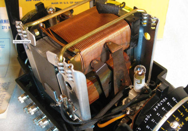
Here are some photos of the inside of a 1941 Type R.  Instead of rollers, it has copper sliders than rub along the coils.  The photos show the sliders, what the coils look like after almost 75 years of use, and the condition of some of the internal wires, where it looks like heat or age (?) has caused some swelling of the insulation.  The insulation is not crumbly.  The resistor is between the outputs of the two circuit breakers; tapped off in the middle is the red short light.

DSC01576

DSC01578

DSC01575

DSC01577

Attachments

Images (4)
  • DSC01576
  • DSC01578
  • DSC01575
  • DSC01577
Last edited by RJR

Add Reply

Post
The DCS Forum is sponsored by

OGR Publishing, Inc., 1310 Eastside Centre Ct, Suite 6, Mountain Home, AR 72653
800-980-OGRR (6477)
www.ogaugerr.com

×
×
×
×
Link copied to your clipboard.
×
×