
Louis,

So if I set up power districts, can I still run conventional?

Not easily. However, if you use a TPC (properly), you cannot run conventional unless you use a Lionel Cab-1 to vary the voltage through the TPC.


I suggest that you just use the TIU's variable channels as they were intended to be used and stop being concerned about a power scenario that may never happen.


 heres where i am at.  After trying 8-12 different combinations with my drops and making stratigic cuts from 8 blocks  -6 etc  


I have been going back and fourth doing several tests .  It is apparent once you have 20-25 ft of wire coming out of a TIU channel(with other drops as well)  you might as well forget about any decent signal coming out the other end. (havnt ried any "Magic "  bulbs yet- However On my very longest loop. I have finally acheived tons of 10 s and 7-8-9 s  almost 3/4 of the way around .  Another 30 40 ft of track 5-8s. Then about a 30-40 ft run of 4-5-6s.


At this point -I would have to start srewing up my layout and ruining my ability to run  conventional.So Im done chasing 9s and tens on this first mainline.


Heres the kicker- I only have the loop cut in half and 6 drops hooked up. No matter what combination i tried starting with 4 blocks originally and 4 drops then going to 8 blocks and 8 drops. The more wire i ran off the one channel to get  farther out into the layout distric  drops, the worse the signal got everywhere.

In addition until i brought it back to only two blocks  and 6 drops is when  i finally got all the 10s and 9s as stated above.I know this is the exact oppisite of what suppose to be done but its working.  The whistle -reverse - and speed control work the entire way around even with the lower number at the very farhest back corner of the layout. At this point I beleive i would need another ZW and another  TIU if i had to follow the power distric rules.


Except for maybe some light bulb experiments I am going to move on to the other 3 mainlines.

Very frustrating, I came up for dinner and then when i returned the signal strentgh had changed in some areas at one point.


Once i get more accomplished i will make an exact dimension of mainlines  and length of wire and drops  with signal strengths and maybe you guys can give me a few more ideas to try.


At one point i was considering moving only the tiu to the middle of the layout and running the power wires from the ZWL. This way the feeds from the TIU wouldnt have to be as long. However the power wires from the ZWL to the TIU would be about 18 ft long.


Thanks


Last edited by Patrick H

I learned a few things from this thread. Louis has gone into new uncharted waters and his plan seems to be navigating the waters quite well. He is not alone in wanting more than 200 watts on the track.


Two bricks going into a TPC 400 is a accepted practice. He added a TIU between the bricks one channel for each brick. and the TPC. It sounds like a better practice than running 2 bricks into 1 channel of a TIU and operating beyond the specs of the unit.


I have a question. Is there a signal drop if one channel has the signal turned off. If no signal drop would only one TIU channel be needed? The 2nd brick could run directly into the TPC 400.

Jim,

I have a question. Is there a signal drop if one channel has the signal turned off.

There would be a drop in the distance that the signal could propagate. i.e., how many linear feet of track it could support.


Regardless, this is a bad idea, since every DCS signal generator, by the nature of its components not being mil-spec, generates a unique copy of the DCS signal. This will confuse DCS engines from time to time. Often, I've seen this kind of behavior when a PS2/3 engine followed by passenger cars with dual pickups crosses between one TIU's tracks and another.


Further, there's no way of knowing how the variation of track voltage wthin the TPC will affect the DCS  signal.


On the plus side, I really don't believe that any permanent harm will come to the TIU, TPC or the engines as a result of this exercise, other than temporary loss of engine control.

I have a TPC before the TIU and that works. Louis has his after the the TIU and it works. Not a lot of empirical evidence but evidence it works nonetheless.


Are you saying Louis would be better served if he shut off the signal on one TIU channel? If true then I think he should just run one channel with a brick and the 2nd brick straight into the TPC. He would lose the E-stop on the DCS handheld this way. 


With 2 signals on the track. The signal generator reader in the engine may be saying 10s when in reality it is something else. Maybe, each signal is a 7. 

Last edited by F&G RY

Jim,

Louis has his after the the TIU and it works

That isn't necessarily correct. It works at present, under limited, basic circumstances, until it messes things up.

Are you saying Louis would be better served if he shut off the signal on one TIU channel?

 No. Turning off  the signal on one channel trades off part of the problem for an overall reduction in DCS signal strength.

The signal generator reader in the engine may be saying 10s when in reality it is something else. Maybe, each signal is a 7.

Not exactly.


A DCS signal test is just the TIU sending out p[packets and getting acknowledgement back from the engine. The number if packets received back vs. the number sent determines the signal strength. When this is happening, there's nothing else going on.


However, that's not the whole story. With a signal strength of "10's", if an engine receives multiple occurrences if the same packets, or if there's interference from another signal generator, errors can crop up, regardless of how strong is the DCS signal.


Louis may have great results, right up until there's a problem, although what he's doing is not something that others should emulate.


Regardless, it's his RR and he can run it as he sees fit. However, if there's a problem down the line, troubleshooting it will be  extremely difficult.

Louis,

I would solve ALL other concerns of over powering and mixing outputs correct? 

No, not correct.


Now you would have 2 separate transformers feeding the same tracks, without any benefit of being "blended"by the TPC. This is an unsafe situation and pretty much defeats the purpose of the TPC.


There is no "free lunch" here. The only way that you run this safely is one of the following:

  • Run 2 bricks directly into the TIU in Passive TIU mode, use TMCC or Legacy to control the output of the TPC to run conventionally, and give up the E-Stop capability
  • Run one brick into each variable channel and operate in command using ALL TIU TRACKS and in conventional using a separate throttle (variable channel) for each loop
  • Run one brisk into one one variable channel and run both loops off of the one channel with a total of 10 amps
  • Use 2 Z4000s with two DCS Remote Commander receivers and create a single Z4K TRACK that will control both loops simultaneously.

We've pretty much beaten this to death, so pick one of the above, or just do what you were planning to do and don't complain when anomalies crop up.


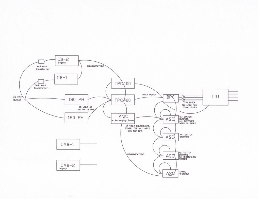
Two(TPC's)(Track Power Controllers) can be wired to the input of a BPC (Block Power Controller) which allows the (TPC's) and either/or for the (4) BPC output power districts.

There is a detail for (4) TPC to (2) Power districts. Same equipment.

Older IC Controls BPC's  Lionel BPC's have slightly different commands.

Acc#1, Aux1 Connects TPC#1 to Block #1 output of the BPC

Acc#1, Aux2 Connects TPC#2 to Block #1 output of the BPC

Acc#2, Aux1 Connects TPC#1 to Block #2 output of the BPC

Acc#2, Aux2 Connects TPC#2 to Block #2 output of the BPC

Acc#3, Aux1 Connects TPC#1 to Block #3 output of the BPC

Acc#3, Aux2 Connects TPC#2 to Block #3 output of the BPC

Acc#4, Aux1 Connects TPC#1 to Block #4 output of the BPC

Acc#4, Aux2 Connects TPC#2 to Block #4 output of the BPC


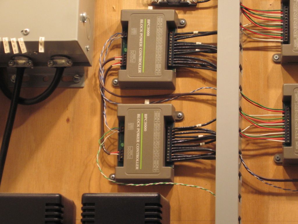
IC Controls BPC's (Block Power Controllers) lower right of large accessory transformer upper left. 

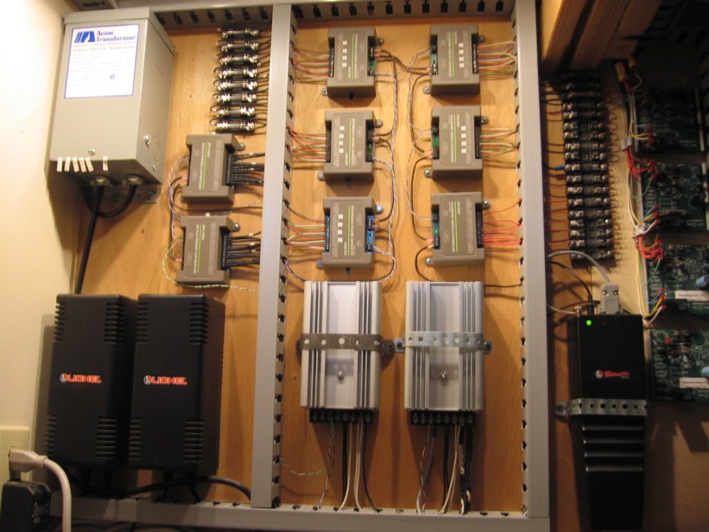
(2) IC Controls Block Power Controllers fed from the (2) silver Box Track Power Controllers pictured.  (8) Power districts.


You may want to install the TIU in passive mode. DCS and TMCC may work better in passive mode/or not.  I'll let Barry explain that. 


That should give you a Choice (Either/or, but not both at the same time) of (2) TPC's for (1) TIU Channel.  There is a detail for (4) TPC's to (1) TIU Channel as I mentioned.  

Best wishes on your project. 

Mike.  


Last edited by Mike CT

Louis,

1st Barrys people skills and smart mouth leave something to be desired!!  WIERD


2nd Patrick invites me to his thread then changes the name like I hijacked his post!!  WIERD


And if you read through this forum on a daily basis you'll see the SAME WIERD STUFF happening every hour in 95% of the threads. No wonder I was told not to talk to Barry! No wonder why I know guys who wont post on this forum cause of this WIERD BEHAVIOR

Yeah, sure, everyone else is weird and you're the victim? I don't think so.

As far as this thread..... I am out of here!

At last - good news.  Bye-bye!

Originally Posted by Louis:

Mike - Thanks for this. Looks interesting. Im going to explore this. Also, thanks for the traction tire on my 844 at Patricks.


2nd Patrick invites me to his thread then changes the name like I hijacked his post!!  WIERD


Louis,


I only changed the thread name in case someone in the future does a search and wants to know how to do the TPC thing.To help others, Thats it-nothing more. Alot of good information from Barry and Mike CT and other forum members. You know me I dont get excited about much. No biggy to me at all. I took the advice from some members here and experimented until I got it working  to run  all 4 mainlines with passenger cars on them. I happy at this point so far.

Your question however was alot newer and provided alot of insight to others who want more power as you do, hence the topic change.More improvements to mine will be made as i learn more. Knew that going in.

For my  layout DCS will  take  a little more  finagling to get perfect because of some long runs i need.Just got to learn more.

 Once i get exact drawings and measurements I ll start another thread to get some more tips(maybe should of did that first)to approach it scientifically instead of generalations. That way maybe someone else with same amount of track to drive signal through may have more tips. 

 with forums sometimes you dont get the essence of how someones trying to communicate with you.If you take it the wrong way you might get offended  as you seen earlier in this thread.All good here buddy.


Last edited by Patrick H

Patrick,


As I started to describe the issue with cutting tracks for DCS Engines to accommidate non-derailing, I tried to label the picture below, blue lines-  insulated joint, white lines-  jumper to connect rail potential, white dots - to show the common from the transformer and green dots-  isolated rail for signal indications.   


I came to the conclusion it is not the track cuts in this example but maybe track geometry, but thought I would attach the picture for reference on my Signal Indications.  


With a front driver on the plastic frog and rear driver with the rubber tire on it (and maybe a switch that is not perfectly flat), provides a slight teetering effect where the engine struggle to find an outside rail to conduct through and because allot of the MTH Steam do not use the trailing truck or tender for picking up the out side rail conduction, issues develop.


SwitchIssues


Other items I would like to comment on:


I only use on 180W brick per channel.  I have had a Z4000 provide enough current through the variable channel of the TIU because of a high resistant short (a pair of pliers on the track), where the Tranformer would not detect it and melted the BJT's (I think this is the right term) inside the TIU .   Very disappointing these unit are not more robust.


As far as the comments regarding modifying lionel trains to run in conjunction with DCS, who wants to make changes to an new engine and add a choke? I am not a fan and would rather put up with the degraded signal.


I see the limits of the TIU only being 180W as an issue and would like a more robust unit.  There are lots of trains that pull some heavy amperage (such as K-line 21" Car Zephyr train going up a steep grade) where a second train on the same track (or block) would be a struggle to prevent exceeding the 180 Watts.


If i had better vision of the final product of how my signal system would work i would not have non-derailing switches, allot of work wiring and cutting.  Real railroads running CTC do not have this, matter of fact they haveswitch machines with lock rods that would prevent this.

Mike

Attachments

Images (1)
  • SwitchIssues
Last edited by Hump Yard Mike

Thank you so much for your explaination Mike. As I explained a bit ago . I am working on some pictures from RR track. Gonna clean up the file and post a new thread of the layout with only each loop showing and get more feedback from people like you Barry , mike CT etc..who have done this as well as others who have got strong signals all around on  a little bigger layout.  Right now i do have good enough signal to run DCS engines but not solid 8-10s all around.

This is what i am working on now. This is the lower loop. It only shows one mainline but their is a identical one running parrallel with it it.

I just got the last of my "finishing"parts in today  ,banana plugs,  etc...

Once i get all 4 drawings done I will approach it more scientifically with the help of you guys.And see if i may have to get another TIU if suggested. Only thing is, I really dont want to lose my conventional running ability.If so I will have to make a choice.

You can see my challenge below and this is just a simple loopThe very bottom left pinisula is where the signal is the saddest ,from the top of it back to the back wall then climbs high again as it makes the top left hand corner after the straight away along the left far wall. Again when the right time comes here soon ,I d appreciate your input.

Thanks

BLUERIDGE_MOUNTAINSTR2

BLUERIDGE_MOUNTAINSTR1


Attachments

Images (2)
  • BLUERIDGE_MOUNTAINSTR1
  • BLUERIDGE_MOUNTAINSTR2
Last edited by Patrick H

"I see the limits of the TIU only being 180W as an issue and would like a more robust unit.  There are lots of trains that pull some heavy amperage (such as K-line 21" Car Zephyr train going up a steep grade) where a second train on the same track (or block) would be a struggle to prevent exceeding the 180 Watts."


Mike


K-Line cars are very power hungry,especially if they have stream lighting with 18 volts input. I suggest converting to LED lighting or at least dimming them by half by putting a diode in series to the lighting.


Dale H

Originally Posted by Barry Broskowitz:

Louis,

I would solve ALL other concerns of over powering and mixing outputs correct? 

No, not correct.


Now you would have 2 separate transformers feeding the same tracks, without any benefit of being "blended"by the TPC. This is an unsafe situation and pretty much defeats the purpose of the TPC.


There is no "free lunch" here. The only way that you run this safely is one of the following:

  • Run 2 bricks directly into the TIU in Passive TIU mode, use TMCC or Legacy to control the output of the TPC to run conventionally, and give up the E-Stop capability
  • Run one brick into each variable channel and operate in command using ALL TIU TRACKS and in conventional using a separate throttle (variable channel) for each loop
  • Run one brisk into one one variable channel and run both loops off of the one channel with a total of 10 amps
  • Use 2 Z4000s with two DCS Remote Commander receivers and create a single Z4K TRACK that will control both loops simultaneously.

We've pretty much beaten this to death, so pick one of the above, or just do what you were planning to do and don't complain when anomalies crop up.

I said 2 bricks one going  through the TIU to the input of the TPC. The other would go directly into the TPC input. The power is blended in the TPC and then into the track.


Appears to be about 300 ft (294ft) of track.  One loop, each red  block 1 ft.  Split the loop, (2) equal parts,  still 150ft per TIU channel.  IMO still pushing DCS signal limit at 150 ft.  100 ft or less per TIU channel would be better. 

I stand corrected.  Note Barry's comment below. 


My comment was based on work we did on the TCA Fort Pitt High Rail modular layout.  Once we split the loops, 90 ft per channel v.s 180 ft total loop,  allowed for more consistant operation with revision L TIU's. 


Powered sidings with TMCC or Legecy engines setting on the track also effects overall signal strength.


You got some work to do. I'd start with Barry's book, a lot has been hashed-over for sometime. 


 Patrick, you need to talk to Neil S, PRRMiddleDivision on the forum.   He added DCS to his large layout with a lot of work and eventually as many as (4) or (5) TIU's. I believe most are in passive mode.    He has a very nice layout similar to yours.  I did a search for the tread on his DCS install but could not find it.   May have been before OGR switched providers.  Mike.        

Last edited by Mike CT
Originally Posted by Mike CT:

A Patrick, you need to talk to Neil S, PRRMiddleDivision on the forum.   He added DCS to his large layout with a lot of work and eventually as many as (4) or (5) TIU's. I believe most are in passive mode.    He has a very nice layout similar to yours.  I did a search for the tread on his DCS install but could not find it.   May have been before OGR switched providers.  Mike.        

I talked to him the other day.  We are  going to get together at some  point. We should to as well  when you get a chance.

For what it's worth, My friend Jack Pearce's(lighted vehicle guy at York) layout is single track with a number of sidings, yards , turntable and about 8 scale miles of main line track. This layout runs really well but it's command only.

The room is about 80 feet long and divided into 4 sections, each section has a tiu and controls all the track in that section whether main line siding yard.

4 sections , 4 tiu, one  tiu is  located in the center of each section.  Since the layout has only one loop a train travel through all tiu zones to completely go around the layout once. (about 15 minutes)  We have a great signal following broskowitz's wiring suggestions using paired wires and terminal block for each channel. Wiring was pretty easy, one block at a time, signal test, then 2 blocks signal test. when we ran out of signal we started over again with a new channel and eventually ended up with 4 tiu in super . This is a fun layout and guests are handed a dcs remote when they come over and put to work..... Sometimes away past my bed time.

I can't imagine trying to set this layout up for conventional as well. we'd need 8 z-4000s for power and the receivers

One block at a time...

Post
The DCS Forum is sponsored by

OGR Publishing, Inc., 1310 Eastside Centre Ct, Suite 6, Mountain Home, AR 72653
800-980-OGRR (6477)
www.ogaugerr.com

×
×
×
×
Link copied to your clipboard.
×
×