
This site, if you sit too long with it without adding anything, times out. The text will upload, but the images will not. I did the first two, watched a few hours of streaming television. When I got back to it I added the remainder of the images which did upload. Always aiming to satisfy my loyal readers, here are the two missing images.

The solder applied to the LED locations at the 1mm gap.

NHH Preparing Tape for LEDs

Solder applied at the power lead connection points.

NHH Solder Prep for Power Leads

Had a dentist appointment… look ma, no cavities. A cardiologist appointment… AFib is there, doing fine and keep doing what I'm doing. And a haircut. Needless to say had about five minutes in the shop. I did get the 3rd floor plate cut in half and cemented the added lip to engage the other half, and that was it. Tomorrow will be more productive.

Attachments

Images (2)
  • NHH Preparing Tape for LEDs
  • NHH Solder Prep for Power Leads

Thank you all for reading this (for over 10 years, I might add). It's amazing how much work you can get done when you have an entire afternoon. I got a lot done today. But first, a word about what makes my working in the shop even more fun. My 15 year-old iPod finally gave up the ghost. I had it sitting on a JBL sound ring that gave decent frequency response. Of course when I was in other parts of the shop, I couldn't hear it very well.

With the iPod dead, I was going to buy a blue-tooth speaker so I could play tunes out of my iPhone. My wife suggested using my AirPod Pros that I have. I had thought she wouldn't want me to be isolated with sound-cancelling pods in my ears if she wanted to call me. But, she could always message or phone me. She said, we have them, you should use them.

Well… the sound is terrific. Since my phone is always with me, I get music throughout the entire shop and layout room which is quite large. I'm telling you all this because a four hour work session runs the AirPods our of battery. That's how long the session was. You can get more time on them by putting them in the charging case for some minutes. The case can charge the AirPods for up to 24 hours.

I got the 3rd Floor supports done, the 2nd floor lighting done. The 3rd floor lighting done, the attic floor supports done. I got the roof done and roofing material installed. And I got the building's mortar applied

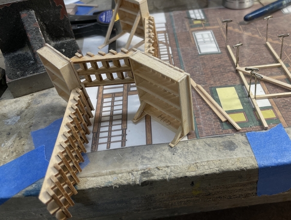
I wanted the floor supports to do double duty as visual breaks so you wouldn't look straight through the building. I'm not detailing any upper floor interiors. You can't see them and they take a lot of time and effort. But I am going to selectively light some areas to make it look "lived in". I chose some scrap plywood for the 3rd floor plates support since it will be structural and I didn't have any floor ledges on the perimeter like I did with the 2nd floor plates. I made a cross lap joint that positioned the bearing wall so it cleared all the side windows. The notches are wire clearance spaces so they don't get pinched.

NHH 2nd Floor Partition Lap Joint

The cross-lap fit was so tight I didn't need any glue. Here it is in place on the 2nd floor plates. Nothing glued. I measured these wall heights with the 3rd floor plate in position, marked the wall, and transfered that measurement to the plywood. I scribed the ply with a digital calipers set to that height. I cut them on the scroll saw and trued up the edges on the wide belt sander.

NHH 2nd Floor Partitions

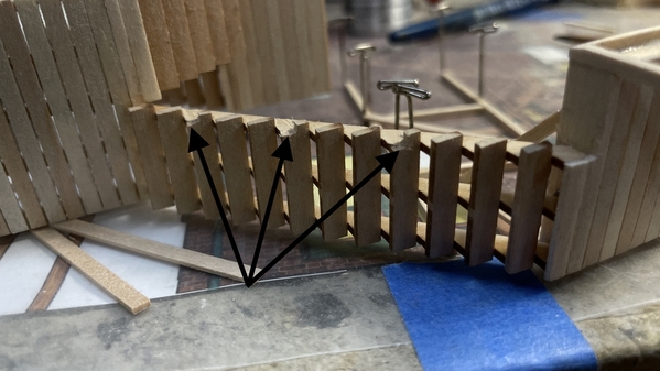
I chose to light one room in the back right side and one in the front left side. I marked these locations on the underside and noted by arrows which direction the leads had to head to get to the proper place to go downstairs. (inside the blue highlights).

NHH 2nd Flr Lighting Plan

These circuits went in nicely. The 3rd floor plates fit in nicely and are level. With the new "Split floor method" there was no need to cut all those relief cuts to clear the window trimming.

NHH 3rd Floor Plate Final Fit

The 3rd floor partitions ARE NOT load bearing since the roof has floor ledges surrounding the perimeter. I was able to use styrene sheet to do this that serve just as light blocks. I used the styrene left over from the laser-cut floors that I'm not using. Again, it's a cross lap, but in this case, I use score-and-snap methods to cut all the pieces and the cross-lap. Since the cross-section was so thin, I added 1/4" sq. stock to aid in glue up and add stability.

NHH 3rd Flr Patitiions

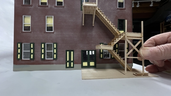
The 3rd floor lighting followed the same method as the other with a different room spacing to add interest.

NHH 3rd Flr Lighting

Notice the yellow electrical tape on the power leads above. I'm identifying each LED circuit with color-coded electrical tape. I can only have three LEDs per circuit with my 12 VDC power supplies and each set needs its own CL2N3 LED driver chip. When all the circuits come down below, I'll need to be able to differentiate them. The colored tape did the trick.

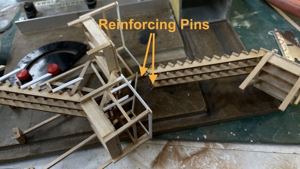
The roof plates are also made from that left over styrene. I measured their width and length directly from the model with the attic plate in place. I then made roof "trusses" to hold its shape separate from the laser-cut trusses I previously epoxied in place. I did this because I'm not sure how I'm going to fasten the roof proper to the truss system. When the plates are on, the trusses are buried and I'm not sure how the adhesive will work. This way, the roof is a separate assembly that may be able to not be glued at all. I sanded the peak edges so they mated better, added 1/4" sq. reinforcements and ultimately (not shown) added thin sytrene sheet stock to reinforce that peak joint.

NHH Roof Supports

Here's the roof fitted in place.

NHH Roof Fitup

Here's the eaves overhang at the rear.

NHH Eave Overhang

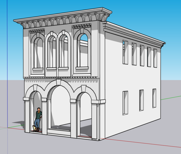
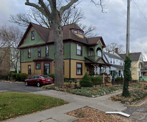
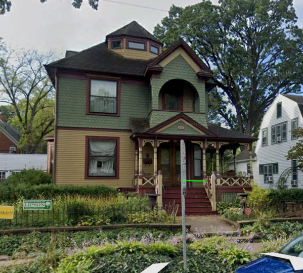
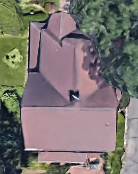
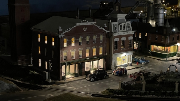
For roof covering, I went contemporary using vinyl sheet roofing as I did with the engine house. This is not far fetched. Google Earth photos of the building show a white roof and it very well could be a Duralast vinyl membrane. And believe it or not, I just noticed that this building has four chimneys, not two. It's hard to see them on the right side due to the proximity to that lovely 2nd Empire structure next door.

Screenshot 2023-05-03 at 6.45.51 PM

I used white duct tape to do the roofing. It's already 2" wide so it's a good size to just use straight off the role. I have to cut the holes for the chimney. I can print two more chimneys. Not a problem.

NHH Roofing Matl Applied

The white interior trusses show up through the roudel window in the pediment. I airbrushed all the front facing surfaces of these trusses a flat brown. This is now what you see when looking inside. Again, with the window in place, you won't see much. The attic will not be illuminated.

NHH Roof Trusses Painted

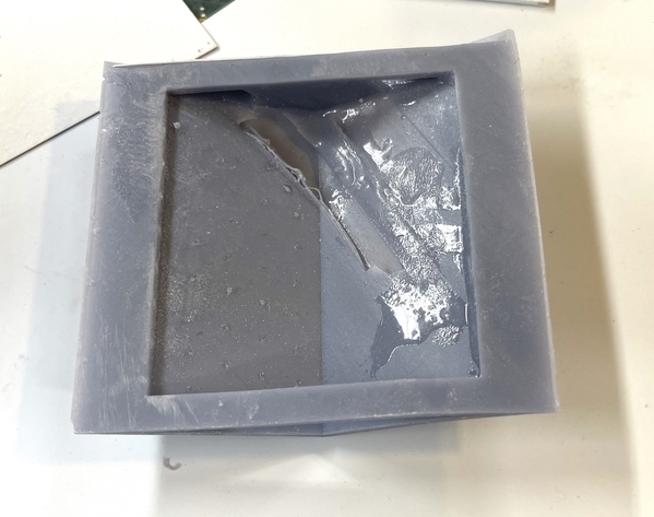
It was finally time to attack the mortar lines. Unlike my past brick buildings, instead of using joint compound and scraping off with a single-edges razor blade, I chose to try something new. I'm using Bragdon Enterprises mortar-colored weathering power. This is basically very finely ground chalk. I tried it first on the chimneys and corner thingys, and was very pleased with the results. You liberally apply it with a brush and then I wiped off the excess with a cosmetic sponge.

NHH Bragdon Chalk Mortar

I had no excuses left to proscrastinate any longer so I just dove right in. I did the front face first (probably should have done it last when I had more experience), and found that after brushing it on, rubbing it in with a nitrile-gloved finger set the powder into the more lines better. I did find that the acrylic laser-engraving was deeper and more defined than the styrene  laser-engraved parts in the upper front. The styrene did not hold the powder well at all, and frankly, wouldn't have held joint compound either. Not sure what I can or should do with this area.

This is mortaring in process.

NHH Applying Mortar

And here's the wall wiped and finished. Looks pretty good in my estimation. In areas that had a lot of powder I used my airbrush without paint to remove it.

NHH Rt Side Mortar done

And here are two shots showing all four sides.

NHH Mortar Done 1

The corner seams will be partially obscured by the downspouts.

NHH Mortar Done 2

I don't know what I should do at this point. While it may benefit from a flat fixative spray, that may actually destroy the effect. I really can stay the way it is. Any thoughts?

So there you have it. Four hours of progress...

Attachments

Images (17)
  • NHH 2nd Floor Partition Lap Joint
  • NHH 2nd Floor Partitions
  • NHH 2nd Flr Lighting Plan
  • NHH 3rd Floor Plate Final Fit
  • NHH 3rd Flr Patitiions
  • NHH 3rd Flr Lighting
  • NHH Roof Supports
  • NHH Roof Fitup
  • NHH Eave Overhang
  • Screenshot 2023-05-03 at 6.45.51 PM
  • NHH Roofing Matl Applied
  • NHH Roof Trusses Painted
  • NHH Bragdon Chalk Mortar
  • NHH Applying Mortar
  • NHH Rt Side Mortar done
  • NHH Mortar Done 1
  • NHH Mortar Done 2

I’ll say you got a lot done!  I had missed that it has a peaked roof.  The work on the floors and room dividers is well worth reading!  
I have seen these white roofs for some time, but never knew what they were.  Duralast vinyl membrane.  When I used chalk for mortar, I didn’t spray any clear coat over it.  Pat has a good suggestion on that topic.

I took your advice (and that or Joel Bragdon at Bragdon Enterprises) and ran a test. I sprayed half of the test article with Dullcoat. The results speak for themselves.

NHH Mortar Seal Test

I'm not going to coat it with anything.

Spent a lot of time today installing the chimneys. While using the Duct Tape was easy to apply. It was the exact opposite when I had to manipulated it when I wanted to install copper flashing around the chimneys. It's not my best work. It was much easier to pull this off when I was using the Rail Scale Victoria Shingles. First I had to cut the holes in the roof. I first tried just wearing my way through the thick styrene, but it wasn't working. I then tried the super-fine razor saw and a regular razor saw and was still not right. Finally I used an Xacto sword saw that can be started in a small hole. This worked pretty well. As usual, the first hole was where I gained all this insight and the second is the one that came out nicely. Yes… there are teeth on the straight side of that blade.

NHH 2nd Chimney Install

After fitting the chimneys I peeled back the roof coating around the holes and worked the copper tape into the areas around the chimney. It was a iterative process. After putting down the copper I had to fold it back along with the roofing material. I then glued the chimney in with med CA and accelerator which trying to keep it plumb. The first one was a little off plumb and again, the second one was perfect.

NHH Chimney Flashing and Corner Post

I also had to open the front corners to the corner thingys could settle down onto their bases.

Here are both

Im posting now so I don't lose the images. I'll be back.

I'm back after watching some shows. You can see a roofing patch that I made after messing up some of the duct tape when manipulating it to add the flashing.

NHH Chimneys Installed

I did another test to see if I could successfully place the store window decals on the back side of the glazing. The test was successful. Here are the results.

NHH Decal Test 1

I then applied, with some difficulty, the window decals on the insides of the windows. The decal over the transom at the apartment entrance is and image of that entire window including a hint of the light in the foyer and a reflection of the street tree in front of the store. I'm annoyed that my windows aren't pristine.

NHH Window Decals Applied

Last thing I did was build the large banner sign frame. I intended on making it entirely out of styrene, but did not have enough of the styrene square stock for the rim, so I substituted 1/16" sq. strip wood. To adhere wood to styrene required thin CA and accelerator. Behind is the large decal of the store with my town's name on it.

NHH The Banner Sign Build

I airbrushed it with Deep Green and let it dry overnight. Tomorrow I will gloss coat it, add the decal and airbrush a flat seal coat.

NHH Banner Sign Paint

I'll mount the sign when it's dry. I am now ready to start installing all the other windows. I've asked the store owner to take some more interior pictures looking down the rows in the main store, which I didn't get in my January photo shoot.

Attachments

Images (15)
  • NHH Mortar Seal Test
  • NHH 2nd Chimney Install
  • NHH Chimney Flashing and Corner Post
  • NHH Chimneys Installed
  • NHH Chimneys Installed
  • NHH Decal Test 2
  • NHH Decal Test 1
  • NHH Decal Test 1
  • NHH Decal Test 2
  • NHH Window Decals Applied
  • NHH Window Decals Applied
  • NHH The Banner Sign Build
  • NHH The Banner Sign Build
  • NHH Banner Sign Paint
  • NHH Banner Sign Paint
Last edited by Trainman2001

Thanks to all. Another good session and this building is really coming along. All the windows and doors are in!

But first I put on those spiffy lintels. The hand painting really paid off. They're adhesive backed so the only challenge was to set them on aligned correctly. I noted this before when first posting about them that it was gratifying to see how nicely the upper ones aligned to their window openings and then joining one another, and that the translation from SketchUp to Coreldraw to laser cutting maintained that relationship perfectly.

NHH Lintels Installed

Next came the front windows. The way the windows go together, there is only 3M self-adhesive on the upper part of the frame since the glazing is stuck to it on the bottom sash. To make sure the windows stay in place I had to apply a coating of MicroSoft Pressure Sensitive Adhesive (PSA) to the bottom half of the inner rails. I carefully seated the windows and applied pressure so they would adhere well.

This shows the sticky and un-sticky parts of the window assemblies.

NHH Window Gluing Challenge

And this is where the PSA has to go to hold the bottom half of the sash to the inner mounting rails.

NHH Surface Needing PSA

Here's all the front windows installed. It went quick quickly.

NHH Front Windows In

I followed this plan around the entire buildiing. The rear doors also required two different adhesives. I used PSA to stick the glazing to the doors, and med. CA to hold the doors onto the inner rails. I applied a thin film of acccelerator to the exposed gluing edges of the doors so the med CA set quickly.

NHH Rear Door Gluing

Like the windows, the doors went together quickly without trouble. I painted the 3D printed door knobs with Testor's Gold Paint Pen. It's nice and bright that doesn't look like gold model paint.

NHH Rear Doors In

All that was left were the shutters. These had a considerable warp and I used the 3D transfer adhesive which pulled them flat (at least for now). I'll see how they hold up for the long haul and use CA if I need to secure them better.

NHH Shutters on

Here's an oblique view showing all those windows.

NHH All the Windows

I also gloss coated the banner sign, but it wasn't dry enough to apply the decal. That will wait until Monday.

Tomorrow is the Kentucky Derby. The Derby and events all during the two weeks leading up to it, are far more important to us Louisvillians than Christmas. Literally, the entire year is defined by Derby, either pre- or post-Derby. It's quite an experience. We used to babysit for our daughter's boys, but they're in college (one's graduating) so we don't do that any longer. We watch it on TV. Our daughter and son in law operate in a different social strata than we and get to go to a lot of parties.

Y'all have a nice weekend.

Attachments

Images (8)
  • NHH Lintels Installed
  • NHH Window Gluing Challenge
  • NHH Surface Needing PSA
  • NHH Front Windows In
  • NHH Rear Door Gluing
  • NHH Rear Doors In
  • NHH Shutters on
  • NHH All the Windows

Thanks guys!

Happy Monday! Louisville survived the two-week Derby experience and the weather held off beautifully. It was an interesting race and people are getting worried about the number of thoroughbreds that died or had to be put down. Something's going on… They are very inbred animals and have a fragile skeletal structure especially in the lower limbs. You could put three race horses in one Clysdale.

Did some punch list work on the building's front; got the door knobs in, glazed the main doors, decaled the banner and installed it, and built the power board and its mounting.

I used some small brass nails for the door knobs. I chucked them in the Dremel and polished their heads, drilled the doors with a #55 drill, inserted them and secured them with a drop of thin CA.

I cut the decal (on white decal stock) and applied it. The left end started losing some of it's color due to water leaking under the clear coat. It also got further munged up. So I cut it off and used the second decal to splice in the repair. You can see the match line, but it's not too objectionable. I then clear coated with Dull Coat.

To install the banner I applied contact cement strips along the top and bottom edges in the back and stuck it on the building.

Lastly, I measured, cut and installed the glazing on the main doors and held them there with PSA.

NHH Front Details Complete

I also added mortar lines to the lower part of the front which I had overlooked last week.

I built the power board out of some electronic bread board printed circuit panels. I bought a selection of these from Amazon to build my grandson's Tesla Coil. I used one to wire up the nine lighting circuits on the turret. In this instance I need five circuits, each with its own CL2N3 LED driver chip. I use the copper foil as a positve and negative busses. The CL2N3s go into a circuit with the power input side to the left of the flat on the casing when looking at the flat. The center tap is non-functional and just serves as another soldering point to hold the chip in place. The right side is the 20ma output that goes to the LED circuit. Since I'm using 12VDC as the power source, I can only power three LEDs in series that are dropping 3.3 volts each. They won't light with four since the total is 13.2 volts being dropped in the circuit. The negative sides of all the LEDs end up on the negative bus. After soldering all five chips into the board, I tested each one successfully.

The board will sit in the stairwell space. While the chips don't get very hot, they do get warm and I made some air holes on both sides of the stairwell using a Dremel with a angle drive and carbide bit.

NHH Electrical Compartment Vents

I then cobbled together a spacing piece (I know, I know… overkill) out of scrap styrene to center the board and keep it in place. In this image you can also see the positive bus on the left with one leg of the CL2N3s soldered to it and the output lead sitting tall where the LED positive inputs are soldered. And you can see the negative bus on the right side. Again, another application of that copper foil tape.

NHH Power Board Holder

And here's the board as it will be installed, when I actually install it.

NHH Power Board Place

Now I have some thinking to do...

If I want to be able to remove the floors for whatever reason, I may want to tie the output leads to a terminal strip where they can be detached, rather than soldering them permanently and directly to the power board. I'm thinking specifically about getting into the main floor that detaches (with screws) to the bottom, but the stairwell is glued to it, so the circuit board will come down with it. If I have some barrier strips somewhere, I could therorectly remove the wires from the upper floors without creating a problem. Ideally, I'd like to have terminals that are soldered to the power board. I will look into that.

Tomorrow I will add some wall paneling to finish off the inside wall around the windows. I'm will use card stock for this. Unfortunately, I install the glazing already. If the window holes were filled with windows, I could have traced their locations onto the panels. Now I'll have to lay it out old school.

Attachments

Images (4)
  • NHH Front Details Complete
  • NHH Electrical Compartment Vents
  • NHH Power Board Holder
  • NHH Power Board Place

That's a good thought. In fact. Here's what I'm buying. I will solder these into the power board giving me access to the wiring without soldering them. I also ordered more LED drivers for my inventory. The pin spacing of 5mm spans two holes on my perf board. I will have to run jumpers from each CL2N3 output pin to the connector's pins since this is technically not a printed circuit. I suppose if I wanted to be cute I could apply the copper tape in a pattern that would simulate a printed circuit. I will think on this to see which is easier; cutting and soldering small jumper wires or using the foil tape.

Screenshot 2023-05-09 at 10.13.35 AM

Attachments

Images (1)
  • Screenshot 2023-05-09 at 10.13.35 AM

G_d bless Amazon. Order connectors yesterday afternoon and have them to install today. And with Prime, no added shipping costs. How can you beat that? The LED drivers come tomorrow, but I don't need them now. Spent some time at the LHS so didn't get much done, but I did get something good done.

I added these connectors to the circuit board.

NHH Circuit Board Terminals

For 8 bucks you can't go wrong. They nest together to make a connector with any number of terminals you want. I chose 7. However, when I reviewed my work at the end of the session I realized I also need one for the negative electrodes, unless I want to solder them to the board. And avoiding that was the whole reason for this exercise. I'll add that next session. I had to trim my board holder (yesterday's work) to clear the newly added terminals.

I did attempt successfully to use the foil to create psuedo printed circuit trails. I had to be careful that the runs did not touch solder pads that would also contact the adjacent trail. A short between these positive trails would not damage anything, but it would cause some of the LEDs to not light. I had to trim one trail to insure that it was not touching. The voltages and currents are so low that any cross-over would have be with direct contact.

I removed the leads I soldered yesterday and changed them to jumpers leading to the terminal's pins.

NHH Circuit Trails

The hardest part was carefully cutting the slices that let the foil slip over the LED driver and terminal's leads. I then soldered everything. Soldering was more challenging than I expected due to the adhesive backing preventing the solder from wetting the cicuit board's solder pads. I had go back and resolder some of them to ensure that contact was secure.

NHH Circuits Soldered

Here's the board from the top showing the terminals. With that big box of terminals I'm going to use them a lot on future installations.

NHH Circuit Terminals

I tested all the circuits successfully which is when I realized I will have to add a negative terminal strip to terminate the field negative leads without soldering.

I also had to come up with a scheme to access the terminal screws when the board is in its space. I opened up a larger hole with the Dremel router so the board could be lifted up beyond the 2nd floor plate exposing all the terminal screws. This should work, but I won't know for sure until I actually start terminating wires. I also routed out another relief cut to keep the wires from being crushed by the 2nd floor.

The power lead wires will go straight down exiting the model through the big bottom access hole that is below the board in this image. This may be overkill as I've noted before, I like to control the wiring when dealing with multiple circuits and electronic components. While it was simpler lighting with grain of wheat/rice bulbs, they were hot and would melt plastic if touching it. They could burn out and they could present a fire hazard. And they weren't that bright. LEDs have none of those limitations, but introduce current management to ensure that they don't go PFFFTTT. If LEDs burn out, it will happen in the instant you turn on the power. I know about grain of wheat melting plastic when I tried to illuminate my Plasticville Signal Bridge with them when I was about 13 years old. It did not end well.

NHH Board Access

Tomorrow work on wall paneling and finishing the upper flooring.

Attachments

Images (5)
  • NHH Circuit Board Terminals
  • NHH Circuit Trails
  • NHH Circuits Soldered
  • NHH Circuit Terminals
  • NHH Board Access

Got the negative terminal strip soldered to the power board. Just poked it through the copper tape bus and soldered it all. I turned the openings toward the inside so the positive and negative field leads would follow similar paths and be accessible from one direction.

NHH Power Board Neg TerminalsNHH Power Board Neg Term Soldering\

Up next was "hanging sheetrock" on the interior first floor walls. I am not doing this work on the other floors. They're basically out of side and I will have window shades on the upper windows.

I used the center stair well as the height measurement for all the wall paneling. I had to trim around the corner and base blocks. I used a combination of digital calipers, dividers, little combination square and eyeballing to determine where the window and door openings would fall. The material is nice cardboad left over from a couple sets of linens we bought from Bloomingdale's. Never through building materials away. I will paint those blocks to match the wall color.u

After cutting the three sides (four pieces) I brush painted them with that craft paint off-white (two coats). You can notice the difference to the un-painted cardboard below.

NHH Sheet Rock Paint

I wanted to trim the window holes and pre-stained some scale 1 X 3. I found a slick way to cut miters for the corners. I used some thinned Aleen's Tacky Glue so I could easily brush it on the card stock. After putting down one side I overlapped the adjacent piece and then with a new single-edged razor, just sliced through both pieces on a 45 degree angle. The result was perfect fitting miniature mitered corners.

NHH Sheet Rock Miter Technique

It didn't take very long to do this for all the wall pieces.

NHH 1st Flr Walls

I attempted to take a picture through one of the front windows to show the back wall. Still needs some more work, but you get the idea. Still need to add some window sills...

NHH Store Interior View

It could also use some baseboards… maybe I'll add those. I'm still not sure about what to do about that interior. Almost every other building in town (the ones that I've created from scratch) has a real 3D interior. And this model is replacing Loopie Louie's Appliance Emporium which has a whole floor full of 3D printed appliances. I will put that somewhere else in town. It's not the shelves that's the problem. It's the thousands of items on those shelves.

Attachments

Images (7)
  • NHH Power Board Neg Terminals
  • NHH Power Board Neg Term Soldering
  • NHH Hanging Sheet Rock Fitting
  • NHH Sheet Rock Paint
  • NHH Sheet Rock Miter Technique
  • NHH 1st Flr Walls
  • NHH Store Interior View

Back from the trip to University of Illinois Urbana/Champaign where number 1 grandson Alex graduated with thousands of others and the rain held off. The Grainger School of engineering and participated with the entire graduating class in the football stadium and then an hour and half later held another ceremony where they all were called up to receive the diploma. That part was done one third of the graduating engineers at a time. As it was it took hours to call up over 700 graduates. They don't get the actual diploma, just the jacket. They mail the actual document. I'm sure they do this bit at all the big universities.

This is just 1/3 of the engineering grads. Ales already has a nice job at Medline in Chicago and he and his mom just found him a studio apartment at the start of the "Gold Coast" in downtown. Life is good!

UofIL Engr Grads

Also today, we exited Spectrum as our internet provider and switched to AT&T fiber optic service. They laid the fiber lines in our our cul-de-sac several months ago, and Spectrum's been having some connectivity problems in bad weather. Our AT&T neighbors did not lose connectivity during these weather events.  Speed into the house is 382mbs and upload is the same speed.

Today, I got a few things done on the model. Not much due to the AT&T guy, but some.

I got the interior walls attached using the transfer adhesive. I also wired up all the lights to the circuit board and thought… thought that I didn't have enough circuits, so I added on more CL2N3 on the board to drive the extra circuit. But I was mistaken by the fact that the 3rd floor only has two LEDs (one on each circuit) so they could be wired in series to one LED driver. I only split the circuit since each light went onto one of the two floor plates. They only required one circuit, so the extra driver was unnecessary. That's what comes when you interrupt the work flow and forget the decisions you've already made.

I painted the three 3D printed interior pieces, but still am not sure about what to do with the interior. I haven't received the added pictures from the store owner. All the lights are lit in this pictue. On the left are the 3rd floor plates with their single lights.

NHH Testing all the lights

I inserted the porch lights into their sockets and lit them. I have to figure out how to get the floors and wiring all put in. I want to make some more light blocks for the upper floors before buttoning up the interior any further.

NHH Porch Lights Lit

More work tomorrow.

Attachments

Images (3)
  • UofIL Engr Grads
  • NHH Testing all the lights
  • NHH Porch Lights Lit
Last edited by Trainman2001

Thanks guys! Sure does seem like yesterday… here was a shot from before we moved from Pennsylvania. This was the layout's 2nd iteration after returning from Germany. Alex, the senior one, was at the controls. Jack's expression is about the most explicit evidence of "pure joy" that I can imagine. That MTH Z4000 is 27 years old and still runs perfectly. It's a nicely designed product. Bought it the first year it was produced. Alex might not have been five yet, but I let him run the trains. Jack had to wait a few more years. They always treated all of my hobby stuff with the utmost care and respect. It's a two way street. Respect them and teach them, and they will return the favor.

Didn't work today, but did yesterday and that's what this post describes.

I got all the wiring hooked up, found out how to get the floors in without wrecking any wiring, and did a lighting test. Making the floors removable was essential, since after the first assembly, one light panel on the first and one on the 3rd floors did not work. Turned out that the screw terminal connections on the circuit board terminal blocks weren't so hot and I had to redo them. That took much longer to do than I thought it would. Using that fine 32 gauge wire might have been a mistake since the terminals are designed for wires with a little more girth. Notice that I like lighting random spaces and not the entire building. Also I used black construction paper on the partitions in the non-lit spaces.

NHH Lighting Test 6

Looks pretty good with the room lights on.

But, as feared, with the lights off, the plexiglass walls and the Rust-oleum red printer were not opaque enough and had a lot of light bleed.

NHH Lighting Test 2NHH Lighting Test 3

To counteract this I brush painted some thick acrylic craft paint on the exeterior walls of the illuminated rooms. Two coats helped a lot. The colonial blue is denser than the green and there was still some leakage. I may go back and do another quick coat on Monday. This image shows the wiring bundle that had to be control while assebling all the walls. I still have to the window treatments, which is another reason for not gluing down the floor panels. I didn't want to go the carboard "sheet rock" route since I didn't have the clearances on the floor panels to accept the added wall thickness.

NHH Black Out Painting

I'm still waiting for Bill Newell to send me more interior images for the first floor. Right now this is what I've done, and it's way too sparse to work, in my opinion.

NHH Interior Progress

Had my semi-annual physical on Wednesday and everything is within targets. I have a tooth getting a crown Monday. When at the dentist last week, I told him about a rear molar that was acting funny when I bit down on something hard. He found it was cracked. We agreed it needed to be crowned at my convenience. My "convenience" was determined while eating my cereal this Monday and having a chunk of that molar decide it was time to separate. Amazingly, while as a kid, I had amalgm in every tooth in my mouth (some of those fillings are probably still there), I never had an adult tooth pulled. And since the advent of the Sonicare tooth brush, haven't had a new cavity in years. It's all about maintaining all the old fillings and occasionally replacing them with crowns. Our dentist says my wife and I are the only people of our age in his practice that have all of our natural roots. Probably stopping smoking in 1975 didn't hurt either.

If I don't get the images soon, I may have to put this aside and work on something else. I just picked up another scale model: the Takom 1:35th scale AH 64D Apache helicopter. I'm getting into building these larger scale helis that are being kitted now.

Have a nice weekend.

Attachments

Images (8)
  • mceclip0
  • mceclip2
  • NHH Lighting Test 6
  • NHH Lighting Test 2
  • mceclip1
  • NHH Black Out Painting
  • NHH Interior Progress
  • NHH Lighting Test 3

Happy Monday!

The 3rd coat of craft paint on the light green did the trick and effectively blocks the light leaking through the walls.

These views show this to be the case.

There a little leakage right at the roof line. I will fix that too. I paved the non-lit room partitions with black construction paper. I only had on piece left, so I finished the job with flat black airbrushed paint. There's light leakage in one of the front rooms from the large hole cut in the partition to pass the wiring harness.

NHH Light Leackage Fix 1NHH Light Lead Fix 3

I need to do a better job of hiding the upstairs wiring...

NHH Light Leak Fix 2

With that out of the way I did the window shades. First attempt was to use Tamiya wide tape, but didn't like that it was sticking to the glazing and the window inner trim, causing it to lay funny. Next attempt was to use post-it notes. However, all I had were lined that showed through. Attempt three was using same Post-it Notes covered with said Tamiya tape. Didn't work. Attempt #4 was to paint some plain white paper, cut into strips wide enough to bridge the inner trim, and then adhere to the trim. I used PSA brushed on the trim to hold the shades in place. This worked!

Attempts #2 & 3.

NHH Window Shade Trial

Attempt #4.

NHH Window Shade Paint

Insides showing shades in place and location of the PSA applications. Light will show through the shades which can be prototypical especially if any of the old folks reading this remember the song from the later 50s, "Sihouettes" by the Rays.

NHH Window Shade Method

Here's what it looks like from the outside with the shades. The shades prevent even more things being seen on the inside.

NHH Window Shade In 2NHH Window Shades In 1

While I'm still waiting for the interior shots, I may place the model on the layout so it can be display for the duration. The floors are not glued place and I'm thinking of using magnets to hold on the roof. The exterior is really almost fully complete. All that's left is installing the corner thingys, building and installing the downspouts and adding the electrical service hookups. Since this building has apartments, it should really have multiple electric meters.

As an aside. We switched from Spectrum cable fed internet to AT&T fiber optic internet. While both Spectrum and AT&T claimed to be 300 mbs download, Spectrum's upload speed was about 15 mbs, while AT&T's is also above 300 mbs. And believe me it is! The upload speed of the pictures for this post almost appear to be instantaneous. We're actually getting about 350 mbs into and out of the house. There are some losses in my router system, but it's still much better. And all this for $5 less per month.

Attachments

Images (8)
  • NHH Light Leackage Fix 1
  • NHH Light Lead Fix 3
  • NHH Light Leak Fix 2
  • NHH Window Shade Trial
  • NHH Window Shade Paint
  • NHH Window Shade Method
  • NHH Window Shade In 2
  • NHH Window Shades In 1

Yesterday's and today's posts are combined...

Since I'm going to put the model on the layout without the interior completed, I still needed to get all the exterior pieces secured. Instead of a permanent assembly, I used Blue Tack temporary adhesive to hold on the roof to the rafters and the corner thingys. This will let me take it apart if I need to.

Also shown in this image is the broken piece of gutter that fractured during drilling of the 5/32" tubing. I filled that today with Milliputt epoxy putty and will final finish it next work session.

NHH Downspout Hole Fracture

I also had to build the downspouts. As by my usual method I choose brass tubing, in this case 5/32" and then treat it too look like aged copper. This consist of steel wooling the pieces to remove any surface imperfections, soak them in JAX Brown/Black chemical treatment and following with JAX Patina. These are chemical reactions, not coatings per ce. However, I couldn't find the patina solution. I also didn't have much left of the blackening solution. After soaking in blackening, and washing, I chose to use Rub-n-Buff patina coating. It's a wax-based product. This picture shows the coating.

NHH Downspout Patina 1st Attempt

However; when I rubbed off the patina coating, the brass was re-exposed and it didn't work. Meanwhile, I was sure I had purchased new bottles of metal chemicals. Sure enough, not only did I buy the new material, but in much larger bottles. When the blackening chemicals are fresh, they do much better job. I steel wooled all the Rub-n-Buff of and put the pipes in the darkening bath. After a wash, I dipped them in the fresh patina solution. This has to dry. You don't wash it off.

The results were good.

I made downspouts retainers out of 0.032" phos-bronze wire, looped with wire looping pliers, clamped and soldered with the RSU.

NHH Downspout Retainers

I also darkened these in the solution. The hole to pass the tails is somewhere between a 50 and 51 drill. I used the smaller (51), but it turned out to be too tight so I opened them up one size.

I marked the walls where the retainers should go and used the drill in the Dremel.

NHH Downspouts install

A closer look at the retainer install. It's held into the plexiglass with thin CA.

NHH Downspout retainer

The last exterior work is the relatively complex two-story exterior stair. This is a similar build to many other timber projects I've built.

I tape the drawings onto my Homosote workbench top. This stuff is great since it holds T-pins very well. I place a piece of polyethylene film over top. All of the is taped so the drawings are taut. I used angle blocks and the T-pins. I started work with the landings. There are three and all different sizes. I have a lot of Northeastern Stripwood left over from the Rick House and planking the floor to complete the entire stairs (I hope). I have laser cut stair sets that will be pressed into service on this project. I will probably put a "concrete" base under this assembly to help hold it together and keep the symetry. Before starting I double-checked to make sure that this drawing accurately matches the actual building. It did!

NHH Building the Stairs

Above was the upper platforms framing (scale 2 X 12s).

The platforms are planked with the left over flooring material (scale 1X3), I sanded the ends to square them up.

NHH Upper Platform Planked

This is the mid-platform which is the largest since it connects to stair cases.

NHH Planking Mid Platform

We're heading out tomorrow for a family affair in Ann Arbor, MI. Work will pick up next week.

Have a nice Spring weekend.

Attachments

Images (8)
  • NHH Downspout Hole Fracture
  • NHH Downspout Patina 1st Attempt
  • NHH Downspout Retainers
  • NHH Downspouts install
  • NHH Downspout retainer
  • NHH Building the Stairs
  • NHH Upper Platform Planked
  • NHH Planking Mid Platform

We had a splendid trip. Seeing family was great (actually extended family since it was the niece of my brother in law's kid that was Bar Mitzvah). Today I first made a full-scale print of the right profile of the building including the stair assembly. I then tested this on site to make sure that the stair had clearance. I'm happy to report that it does have clearance to spare. I then got back to building the stair case. I finished the last landing and then, using the Rusty Stumps (now Rail Scale) wooden stair assembly jig and laser cut stair parts, started building the three flights. The assembly jig does not retain the stair stringers securely enough and they can go out of alignment while building. I first tried using masking tape, but for some reason it was not sticking to the case resin jig. I then drilled a 0.032" hole at the very ends of the stringers and added T-pins. Now it was secure. I had already added a top-stop for the other end.

NHH Stair Case Jig

The stair treads are also laser cut and part of the entire package. They're a little thick, but I'm using them.

I pinned the top and mid-landings to the plans and measured one stringer length, which I cut.

NHH Stair Case Erect 1

I then assembled the stair with the two outer stringers. I added the middle stringer after the treads were in place.

NHH Upper Case Built

I continued this process for the mid to lower landing and then lower to ground. I'm using a piece of ply for the base so the lower stringer was cut to NOT rest on the ground without the base. This is the three flights glued together. I used Aleen's first and followed up with thin CA.

NHH Completed Stair Flights

Where the stairs met the landings I used the deck planking wood and continued the landing onto the stairs.

NHH Top Stair Joint

I tried the stairs in position on the model. Taking this picture took several tries since I was using the phone's camera in the "selfie" mode. Note that the middle landing is not lying square, but that's caused by not having the platform in place to support everything. Don't worry, I will be straight when fully supported.

NHH Stair Fitting

I needed a way to hold all this in reasonable alignment so I could start building all the support and railing assemblies. I cut a piece of 2" X 2" to use. Unfortunately, the piece is not square as it could be, but I made it work. I put a level on top to hold the top square and then measure the long supports. My original design had angle brackets under the upper landings, but I'm going with long poles and trusses to do it.

NHH Stair Fixture

NHH Stair Level

I started to attempt to glue the poles to the flatforms in this position, but quickly found out that it was an exercise in futility. I then went back to "model-plane-method" and pinned the pieces to the building board. This is the first support set. More to follow tomorrow.

NHH Stair Support Assembly 1

Remember how I wrote about keeping your eyes open (and phone camera ready) whenever you find interesting structures to think about building? Well here's a beauty on a street in Ann Arbor, Michigan that we passed on the way to brunch at famous Zingerman's Deli. I probably don't have enough imagery to build it as it, but it could be found on Google Earth to fill in some blanks.

Ann Arbor Gem 1Ann Arbor Gem 2

This house has all the Victorian trappings: fish scale siding on the upper floor, gingerbread trim on the porch, beautiful turned porch supports, neat railing, open balcony, turret room, perfect Victorian color scheme. It's a classic. I have those two books I bought on Victorian architectural details and color schemes. One of these days, I'm going to put them to good use.\

Here's what you can get on Google Earth,

And here's the floor (roof) plan. It measures 31' across the main roof peak (side to side).

L

Left side is still a bit iffy since it's obscured by a big tree. One shot was done in the winter without leaves, but all the rest are with leaves.

Attachments

Images (15)
  • NHH Stair Case Jig
  • mceclip0
  • mceclip1
  • mceclip2
  • NHH Upper Case Built
  • NHH Completed Stair Flights
  • NHH Top Stair Joint
  • NHH Stair Case Erect 1
  • NHH Stair Fitting
  • NHH Stair Fixture
  • NHH Stair Level
  • NHH Stair Support Assembly 1
  • NHH Stair Support Assembly 1
  • Ann Arbor Gem 1
  • Ann Arbor Gem 2

Yes, and they are lovely things. Takes a lot of cash to own one. L'ville has an enormous amount of period housing and the largest collection of late 1800 early 1900 mansions in the USA. Literally square miles of them. Until the US Army Corps of Engineers put in the locks on the Ohio River, all ship traffic from the South and North couldn't pass Louisville due to the Falls of the Ohio. Therefore, my fair city was the fastest growing city in the USA until that event. Lots of manufacturing took place here with the southern raw materials and northern metal parts. When the locks went in, the ships just passed us by and the growth stopped. Now, the city is actually having a rebirth and doing quite well.

Worked more on the staircase today. It was a battle royal and it ain't over yet. I decided to go back to using the wall brackets to support the upper landing and a combination of small brackets and vertical support columns for the mid and lower platforms. Getting the height of these columns was especially troublesome and more work needs to be done to get it right. Here's the first mistake.

NHH Upper Brackets - Wrong

I put the brackets are on the wrong edge of the platform. I didn't realize it (forest and trees syndrome) until I was fitting the long columns I was planning to use and wondered why the brackets were interfering with them. I was able to pry them off and refit them to the correct back wall (which is facing the viewer in this image).

I then scraped the long set of columns. I tried to re-purpose them, but the spacing was all wrong and they needed to be made anew. I handled this too soon after building and, of course, the whole deal fell apart. And I rebuilt it again.

Because of the window spacing on the lower level and the new size of the landing, I couldn't use the long brackets so I built some short ones. I am augmenting these with the columns. In the background you can see the corrected brackets on the upper landing.

I then needed put it up against the building to catch the column height. Holding it still to get the measure was annoying. And I didn't nail it. I was concerned to not torque the angles and put some of the landings out of square. I thought I had the lengths right, but after re-fitting to the building, they seemed be too short.  I figured these two spacers would give me the correct height. While I had those nice drawings, there were enough real-world differences in the material sizes I used to make them good guides, but not accurate enough to cut the columns.

I also found that my v-block on end was just about the exact height of the lower landing from ground level and I used it to help space the lower level columns. Notice the column extend up to the scale 36' railing height.

After fabricating a column footing that will be simulated concrete, I tried it on the building again, and now find that the lower landing columns are too short also, by about the same amount meaning… the long columns were probably correct the first time before adding the footings. This view is not a good representation since it's twisted a bit. I have persistance and will get it right before nailing it all down.

Notice too the phos-bronze pins reinforcing the joints. I did the same thing on the longer columns.

I had to notch everything for the remainder of all the railing stanchions. The upper rear stair will only have railing on the outside since it contacts the wall. The rest of them have railings on both sides. They will be delicate. If I wasn't for the convenient stair kits I had, I was tempted to build it entirely out of styrene; especially now that I'm painting the whole thing.

I still have some work time tomorrow and could finish this up. Due to all the CA holding everything together, staining is out of the question. I made one critical error. I didn't pre-stain all the lumber. If I had done that I would have a natural wood finish. Instead I will paint it. That's prototypical too before the age of pressure-treated lumber.

On Thursday we're on our last of the three marathon road trips. This time to the graduation of our oldest granddaughter in State College, PA. She's matriculating to Penn State's Theater School next fall so she's staying close to home… very close. It's nice when you have a world-class university a couple miles from your house. We'll be back on Tuesday. Over a five week time span we will have been to Champaign/Urbana, Ann Arbor and State College.

Attachments

Images (5)
  • NHH Upper Brackets - Wrong
  • mceclip0
  • mceclip1
  • mceclip2
  • mceclip3

The stairs are complete ready for finishing. The battle raged on all afternoon, but I emerged victorious. Some of it disassembled while handling, but turned out to be a blessing in disguise. It enabled me to get better control of assembling the handrails. Strangely, during the re-assembly process, the lower landing and lower stair flight got turned around so the flight tucked under the 3rd floor flight. This was another blessing since the stair now takes up less real estate. I orginally built the stair with the lower flight outboard of the rest since it was the way the prototype's was. That said, the prototype lower stair was a pull-down, metal fire escape stair so it needed clearance to raise and lower. Since I'm now modeling a fixed stair, having it turn on itself makes design sense.t

I attempted to hold the whole assembly in the Panavise. It worked for a little bit, but didn't really do the job. I ended up hand holding it or resting it on the bench. Keeping it still while attaching delicate parts was an on-going challenge. I had to be very careful with the tightening since it could easily crush the model.

The spindles needed a 45° angle on top. I make a custom fixture on my Chopper to give accurate and clean cuts. Their metal angle guide can't go right up to the blade so it's hard to clip the ends of parts. By pushing it to the left a bit and then adding a cuttable fence, I can cut right to a point.

Here's the upper flight that disconnected with the first railing assembly. I decided to use styrene for all the rails except the corner post. This enabled me to use solvent cement to hold the rail to the spndles. I still had use CA to hold the styrene to the wood. I used 0.030" X 0.080" for the spindles and 0.030" X 0.100" for the railing. Then I ran out of the railing stock and had to substitute 0.020" X 0.100" for one flight. You can see it, but it's not offensive. Actually, the 0.020" stock is more prototypical since it's about 1 scale inch thick. I was very liberal with the CA on this build and it's not a clean build… another reason to paint it.

To re-attach this stair to the rest I pinned it. When in doubt, pin it! Broke a couple of 0.032" carbide bits in the process. This last order of drills I got a 50 drill pack since I really go through them much too quickly.

After installing all the rails, I did a final test on the model before permanently mounting the assembly to the ply base.

Here you can see the mysterious stair reversal which, as I said, I like better. The stair couldn't directly drop from the 2nd floor landing since it would block the door.

I put pins under all the foot pads, drilled the base and installed it. With the pads down tight, the platforms are all parallel to each other and with the gound. I then glued down the bottom flight to the base, thereby securing the entire deal. It is able to free stand.

NHH Stair Complete 1NHH Stair Complete 2NHH Stair Complete 3

When I'm back in the shop on Tuesday, I'll start the painting process. With the stairs complete I can place the model on the layout, while still waiting for the interior stuff to final finish it.

Have a nice weekend. We're on the road again tomorrow.

Attachments

Images (8)
  • mceclip0
  • NHH Stair Complete 1
  • mceclip1
  • NHH Stair Complete 2
  • mceclip2
  • NHH Stair Complete 3
  • mceclip3
  • mceclip4

Sure is. Don't know how many more years we're going to want to make these extended drives. Sure would like a self-driving Tesla. My daughter drove her Tesla Y to Ann Arbor. While it relieves some driving issues, it's not autonomous. A number of makers are including lane holding self drive so it's not unique any longer. On Friday's north drive traffic was very heavy and self-drive didn't provide much benefit, but on the return trip home on Sunday, self-drive was wonderful with long stretches where just an occasional touch on the wheel was all that was needed. According to my kids, I'm too old for a car with all the displays. I will get confused. I'm not confused! And I'm a bit annoyed.

I never wanted my dad to think I thought he couldn’t do something anymore.  Occasionally I would ask if he needed help with some work, but usually I would just observe to see if it was getting done.  He did ask me to help him figure out a few things on the last car he bought.  It was newer than what we had, so I was scratching my head trying to figure out what the manual meant on at least one feature.  😄

Last edited by Mark Boyce

Well… we did it. In four weekends we did two graduations and one Bar Mitzvah, none closer to home than 200 miles (Champaign IL, Ann Arbor MI and State College PA). We drove home from State College on a Monday and Tuesday and traffic was wonderfully light.

I finished the stairs by just using Tamiya Fine Gray Primer, sanding some off the stair treads to show some minor wear, added a few nut/bolt/washer castings and then some minor rust runs. I painted the base a concrete mix of Tamiya Buff and Neutral Gray. I found I had to elevate the base a bit to align better with the doors. I used a scrap piece of foam core to raise it. The reason for this is the power lead is not sitting directly over the previously drilled hole (where the Apppliance Store's lead went) so it was holding the building too high off the surface. I will be removing the Hardware Store when I finish the interior so I will redrill the hole at that time.

To prepare the site I had to remove the Bar Mills PE sidewalk elevator. This was CA'd in place so it left some residue that I had to remove. I had painted the pavement under the elevator flat black. I thought I was going to have to repaint the smooth, but this was unnecessary as the Hardware Store came out further and covered all the old stuff.concrete after sanding it.

And here's the rear with the stairs just sitting there. I will glue them down after the final work is done.

And here are a series of frontal shots.


And at "night"...

In the above you can see a temporary spot for the appliance store; in the curve just north of the Sunday Morning mockup. It's a tight squeeze and should probably go where the Gravely Building now sits.

I'm going to keep bugging the store owner to get me those interior pictures. Meanwhile, I'll be doing some plastic kits. My 3D printer is down. I'm getting a new mother board from Elegoo and that's going to take a while to get here. They're a pretty good bunch. Even though the printer is 5 months out of warranty, they are giving me the new board. It just abruptly stopped working and we're hoping this will solve the problem.

Attachments

Images (9)
  • mceclip0
  • mceclip1
  • mceclip2
  • mceclip4
  • mceclip5
  • mceclip6
  • mceclip8
  • mceclip9
  • mceclip10
Last edited by Trainman2001

Thanks guys! I'm fix'n to let out the contract for cutting Sunday Morning. SketchUp Pro just got a whole lot more expensive. They've just notified users that the price is going up over 40% next year for the year subscription. I just paid this year's renewal at $237.00 and next year it's going to be $346.00. I don't know how they can justify that increase. It's getting really expensive for the occasional user like me.

They have the "Free" version available, but it's no longer a client version residing on your own computer. It's in the cloud. Furthermore, it does not permit using any of the add-ins and extensions that I use. And I have a ton of them including the Podium rendering software, which in itself is an expensive (for me) yearly charge. Together they'll be close to $500/year, and that's way over the top for the hobbyist like myself. To help pay for the software I've cancelled almost all of my print magazines except for Scientific American and Fine Scale Modeling. They didn't add up anything near $500.00. That places software as a much higher expense than the hardware I use. Good 3D printers are $300 or less today.

I don't use SketchUp every day. I use it when I'm designing a project and then not much at all. It averages about 1 to 2 times a month. That's more than $40 every time I touch. That's expensive!!

There are other 3D packages out there. Blender and Mesh Mixer stand out as powerful packages. But they're very difficult to master and I've been on SketchUp since Ver. 1.0 in the 1990s. You can teach and old dog new tricks, but it takes a whole lot longer. I may have to bite the bullet and master them and then dump SU. They're getting piggy.

I'm afraid I have to agree that mastering one of the open-source alternatives is the only sensible path forward for the non-professional.

I use something called SolidPython, which lets me do solid models by writing code rather than directly manipulating graphical 3-D images. It is very powerful, easily supports full parametric design, and is vastly simpler than the mainstream CAD systems. The problem is that it is really only suitable for someone who is very comfortable thinking in code, which makes for a relatively small population for whom this makes sense. For everybody else, picking a package and biting the bullet is probably the only reasonable alternative. FreeCad is probably the most powerful of the free systems, but learning it is kind of a nightmare. I was once fairly good at it, but I've forgotten it all.

Myles, another award-winning building completed.

I have been using Autodesk Light for sketching (design) but it doesn't output anything that can be input into my "FREE" copy of Autodesk Fusion 360 except a DXF sketch that can be copied into Fusion as a guide.

Autodesk offers a "free" subscription of Fusion 360 to students and enthusiasts with yearly renewal.

However, after using Pro Engineer before I retired from Honeywell. it isn't as user friendly as the way you have described SU in previous posts.

For occasional users it's hard to justify the premiums for subscription's they are asking.

Gerry

Last edited by SGMret

I have the free version of Fusion 360, Blender and Mesh Mixer. I was in the process of learning all of them, and not liking it. I then decided to bite the bullet and get my SU pro renewal. Now I'm back to that previous state. SU from its inception was much more intuitive. Things went south when Trimble bought it from Google.

The history is as follows: SU was founded by some fellows in Boulder, CO. Google used it to do 3D drawing for their Google Earth app. They liked it so much they bought the company. Google contiued to offer it as a free package. I was using SU from its beginning before Google. Then Google sold it to Trimble. Trimble clearly wanted to monetize it. They converted the free version, which was full-function product that resided on your own machine, to a cloud version that was very limited in capability. The only restriction on the previous free version was "No Commercial Use" whatsoerver; even if it was secondary.

They then offered the Pro version as a fixed price. Then it became a yearly subscription. And then they raised the price more. Most of the development of this program was done a long time ago. Trimble has made some tweaks, but nothing major. A lot of development was in the outside developer world with hundreds of add-ins and extension to increase the program's power. None of those extensions are available to the free user. You have to buy Pro. Without them, the program is relegated to doing rudimentary things, and is not sufficient for my needs.

The other programs, like Blender, have their strengths. Blender and Mesh Mixer are good at drawing organic shapes with compound curves and contours. However, to use Blender as an example, the variables you have to control with a constant barrage of dialog boxes and choices is mind boggling to me. I can learn! I'm old, but I'm learning constantly. I mastered 3D printer at 75. I learned to make my own decals recently. I learned to draw buildings for laser cutting six years ago. I didn't start scratch-building until age 65. But, I don't like having to learn new things that don't advance my art. I'm having to learn all this because the product that I've been successfully using for 25 years has priced itself out of my reach.

I've just penned a post describing this dilemma on SU's User Forum.

Last edited by Trainman2001

Myles,

I understand completely. It's been 5 years now since the learning experience began with a new 3D software program after using the more intuitive Pro Engineer 3D modeling program as I said above. At the age of 83 I to don't enjoy starting from scratch either.

My back door approach started when I wanted to scratch build PRR style positional signals using styrene. Since I needed 20 or more and had no turning ability that Allan Rail stepped in and agreed to 3D print the finials for me. As you would expect I soon found it would be time consuming and tedious that I started looking for 3D software and printers. You'reposting about 3d Resin printers,together with Alan's posting sparked my interest in obtaining my own printer and required software. Having used AutoCAD drawing software, I was able to obtain a free copy of their Fusion 360 modeling software and began the learning process once again. Based on your past posting about using SU I agree that Fusion isn't very intuitive and sometime can be frustrating and not as powerful. Although forme, obtaining a individual seat license for Pro Eng would have greatly reduced the learning process, the yearly cost of $1000+ wouldbe out of the question thatI took the free option.

I know you will find a solution to your dilemma just as you have done in the past and continue to provide us with many enjoyable projects to follow.

Gerry

AutoCad started out for almost FREE, just to buy market share. Now its close to $2,000 a year per machine.

AND if they find you have been using the software on more PCs than you purchased THEY back charge you.

if you don't pay they shut down your access.... Neat!


It's costly to have coders, software security engineers, sales, owners at the trough.   

Last edited by AlanRail

My decision was sort of taken away from me when I was informed that my automatic renewal was processed through PayPal. I thought about cancelling it, but after discussions with my understanding wife, we decided that it's important enough for what I do. Furthermore, my lower price from last year was the recipient of a $50 new-signing discount. So the price rise was not really as large as I thought (more like 16%) and I will live with it. I really, really didn't want to master new software considering the vast experience I've had with SU.

Thanks Al!

So just how old are you? I didn't start scratch-building in earnest until I was 65. I didn't start doing serious architectural drawing on SketchUp until I was 70, and didn't start 3D printing until I was 75. Age is just a number. We know now that we can keep building brain connections even when old. That said, cognitive learning is different from motor learning. Motor learning is much harder when old and that ability starts to degrade in our early 20s. BTW: I turn 78 at the end of July.

I don't want to hear any excuses. You're too fine a craftsman to set artificial limitations. As Yoda says, "There is no try! There is do or do not!" Remember, I'm here to help you...

Great building Myles. No matter what they charge for 3D it is still faster and easier than my John Henry style of hand building everything. I am too set in my ways to change but you never know.

I think The second part of your sentence tells it all Alan.  “but you never know”.  I think that can be true for any of us.  Loss of fine motor skills could be a driving force for an ‘older’ person to take on 3D printing.

In all honesty, it isn't easy learning 3D software at any point, and age can be a factor. But you don't know what previous knowledge you have (vast knowledge) that can be applied to shortcut the learning process. We're not little kids who are empty vessels where you just pour stuff into. Granted, as older folks you often have to unlearn stuff in order to fit in new stuff. And that can be challenging.

ALAN-


You are clearly an EXPERT on Plastruct.  You know exactly what dimensions your structures need to take to utilize their designs. Like how the stairs , ladders , railings and patterns must be incorporated in your models.

HOWEVER, with 3D printing there are NO LIMITS, no fixed slopes to the stairs, no fixed widths to the railings.  You make up your own 3D patterns. Toss out your X-acto knives!

Very interesting thread!  I have a lot of respect for the two Alans and Myles is a true inspiration to me.  Myles your buildings are gorgeous!  I love realistic scenery and attention to detail that each of you has in spades.  Thanks for sharing your excellent work and thoughts.

Art

You're welcome. Obviously, it does take some time to write thousands of words to create an 11-year thread, but with comments like your's, it's clearly worth it. I've said it many times, but I'll say it again. I get as much value from my readers as I assume I'm giving. More improtant than the tips and tricks we share, it's the friendships I've developed with folks I've never met in person, but find their comraderie valuable regardless. I'll keep this going as long as there's new stuff worth writing about. That said, Mark Boyce and I actually did meet when he bought my Idaho Hotel.

Last edited by Trainman2001

Myles, you said it so well! 

I get as much value from my readers as I assume I'm giving. More important than the tips and tricks we share, it's the friendships I've developed with folks I've never met in person, but find their comradery valuable regardless. I'll keep this going as long as there's new stuff worth writing about. That said, Mark Boyce and I actually did meet when he bought my Idaho Hotel.

I certainly looked forward to meeting you in person when we arranged the meet for the Idaho Hotel.  Even though it was a short time we were together in the Sheetz parking lot, I was greatly pleased with talking with you and your wife.  Meeting Forum friends in person was the big takeaway the two times I went to York before the pandemic.  I value that far more than the few items I purchased.

Hey guys! it's been a while. I've been working on another Battleship New Jersey project. This time I'm creating a cutawat of the five inch secondary battery turret down to the magazines as I did with the big guns. The ship has already accepted the offer.

These are my drawings: They are not compete nor completely accurate as this time.

mceclip1

I've already started printing parts for it. Not sure how I'm going to handle the magazines. It's not a simple question with these guns. There were 10 turrets on WW2 version Iowa Class ships, but only six magazines to serve them. Four of the magazines served two turrets. To make matters worse, they are not directly below the guns they serve. And if that's not enough, There are intervening decks between the gun and the magazines that do not have any gun-related functions other than the powder and projectile hoist trunks passing through these spaces. There's another possibility as shown by this artists drawing. There is a small intervening space and the gun is sort of over top of the magazine. This would be easier to model, but it is not accurate. My model will be more detailed than this drawing.

This is NOT my drawing:

Here's a sample of the printing.

\

This is not the only project I'm working on at the moment… it's one of five.

Another project is a commission I just received to build a nice holiday-centered n-gauge model railroad for the store window of the Newtown Hardware House. The offer is based on how impressed the owner was seeing the results of the hardware store project. We made the formal agreement yesterday. I'm using the little set that I built with the grandkids 12 years ago, and will modify it and tune it up for the store. I'm also creating some replicas of 19th Century buildings extant in Newtown, PA, including the hardware house in n-gauge and another building several stores away. In this tiny scale I can print the entire building instead of printing dozens of detail pieces and having the walls laser cut. To that end, it wasn't difficult to convert the drawings to make them printable as single pieces. I finished the front wall this evening and it will work.

mceclip7

I'm not worried about those micrscopic window mullions. It was silly to even have them on the print drawings. I will either leave them off, draw lines on the glazing or print decals to apply to the glazing with the mullions in place. There was some slight distortionin the area over the right door, but I'm gong to live with it. Frankly, I'm amazed that it printed this well right out of the gate. The entire roof structure is being printed now. I'm printing the other three walls and the exterior stairs as two parts. That will be a miracle if it prints in n-scale. I'm getting a nice fee for the job and will be replacing some engines and rolling stock, plus spiffing up the layout with some more foliage and special lighting.

As a reminder, here's my proud grandsons 12 years ago when the layout was complete. Alex was probably 8 and Jack 6. Alex is now an engineering grad and Jack is a sophomore at Wash U in St. Louis. My only concern with this layout is the very sharp radii curves. They were the result of the small size of the board we had to work with. I'm hoping we can get it running well enough to run unintended hours on end. The boys actually did a lot of work in building this.

I know this an O'gauge forum, but you'll have to grant me special dispensation for this special project.

Oh… and one more thing… the owner of the store has offered to pick it up at my house in Louisville. He often travels in the South, and his son used to live here so he's quite familiar with the place. This eliminated a huge worry of how to get it to Bucks County, PA by Thanksgiving without breaking it.

I'll keep all y'all abreast of all my projects.

BTW: I'm now 78, and the creative juices haven't slacked off one bit. In fact, I feel as good as I ever have. Even my sciatica finally gave up and went away. Life is Good!

Attachments

Images (9)
  • mceclip1
  • mceclip0
  • mceclip2
  • mceclip3
  • mceclip5
  • mceclip4
  • mceclip6
  • mceclip7
  • mceclip8
Last edited by Trainman2001

Myles, thank you for posting!  The battleship turret looks like another challenging project you will do a dandy job on!

The N scale Newtown Hardware building and layout is a great idea of the owner’s.  It looks like the boys did a nice job with grandpa’s help years back!

Happy belated birthday! I’m glad you are feeling good and that the sciatica pain went away.

I’ll look forward to updates when you have them.

I hope I don't disappoint.

I got the roof and the right side wall printed today. The rear wall is on the printer now and I'll print the left side wall tomorrow. All that will be left will be some floors. I got the down payment on the project so I'll be purchasing some goodies for it. It needs trees and shrubs, plus the lighting. I'm also going to get some new cars and engine. I saw a nice Pennsy 0-6-0 switcher which fits the time period the owner wants to hit… the 1940s.

The roof, while printed in a workable way, had some serious delamination in the center causing depressions in the roof surface. Clearly, it needed more support in that area. It's also possible that the drawing itself had some layering that produced wth discontiunity. Remarkably, the chimneys all formed perfectly.

I strenthened the inner surface with some Bondic while pushing down the bulge from the outside while curing the Bondic on the inside which really flattened it out.

I also copiously filled the big depression on the outside and then sanded the heck out of it.

NHH 160 Roof Bondic Patch

There was one other strange error. There were openings on the rear, gable end of the roof. I really didn't want to print this large part over. Besides the 6 hour print time, I didn't want to waste resin. So I patched it with some thin styrene sheet, filled any gaps with Bondic and we're good to go.

And fixed:

So the roof is ready for paint. No shingles in n-gauge.

The right wall came out very well. With a very little clean up it will be ready to use.

I'm also making good progress on the next building. This building, 5 doors down from the Hardware house, was the offices of the Newtown Newspaper and was built in 1876. It has lovely brickwork especially in the arches around the windows, but alas, those bricks are too small to worry about in n-gauge. It only took a couple of hours to get this far. Have to do windows, roof, and doors. Just noticed that two of the windows upstairs are bricked out. I could add that.

Onward and upward.

Attachments

Images (8)
  • mceclip1
  • NHH 160 Roof Bondic Patch
  • mceclip2
  • mceclip3
  • mceclip4
  • mceclip5
  • mceclip6
  • mceclip7

Some more walls completed. Also got the 5" gun body printed today. When I finished the 16" gun project and the Hardware store, I was wondering how I would keep my printer busy. Boy… was that an uneeded worry. It's been working non-stop for two weeks. Got the rear wall done today and the Left wall just finished a while ago and I'll pull it off the machine tomorrow. I will only have the steps to do, and then assemble. I'm thinking of producing a custom decal with the window mullions that will go behind the transparent styrene windows. I was pleased the the paneling on the doors and shutters came out.

NHH 160 Rear Wall

And the gun… The barrel fit the slide nicely and the gun fit between the mounts perfectly. The curator thinks they look pretty good.

The drawing:

5IP Gun Final

And the print.

5IP Gun Print R

The "mount test". I'm going to machine metal trunnion pins to replace the drawn ones that I made.

5IP Gun Print Mount Test 1

Attachments

Images (4)
  • NHH 160 Rear Wall
  • 5IP Gun Final
  • 5IP Gun Print R
  • 5IP Gun Print Mount Test 1
Last edited by Trainman2001

Myles, having worked in N-scale for about 10 years, I think your printed parts and fills for gaps will work great!  Yes, individual shingles and bricks are mighty tiny in N-scale!!  Then when viewing from an average of 2 to feet away, you don’t really notice them!  That 1876 newspaper building is excellent to model also!   The gun looks great as well!

Yes, I can see the printer is running almost non-stop.  You’ll have to pull maintenance on it pretty soon.  Just kidding there.  😄  The thought did remind me of substation breakers.  If we get in “the way back machine” to your marvelous substation model, each breaker type had a manufacturer recommended time to “pull maintenance” as they called it based on the number of operations since last maintenance.  I’m going back to 1990 give or take.  A lot of old breakers were oil circuit breakers OCBs.  They could handle quite a few operations before the substation electricians hat to switch them out, drain oil, and inspect and replace parts.  The newer breakers were filled with sulfur hexafluoride SF6.  They could take a lot of operations.  We had a couple 500KV air blast breakers at one station.  They used a blast of air to extinguish the arc, and could only take about 10 operations before they needed to pull maintenance.  When they opened the sound waves rocked the control house at least 50 feet away.

Sorry for the long winded monologue.  I’m sure the printer will run well for many, many hours of printing!  😊

I have had the most printing difficulty that I've had in years printing the last wall of the Hardware House. This is the left side wall which is basically flat with two windows. It's the simplist print of the structure. The first two attempts had failed supports. The third was a complete failure. All that was on the build plate was the base. The rest was a layer of resin spread out all over the FEP.  I was able to remove all this gunk, but I'm a little dubious about the health of the FEP. I just changed it last week and it's only run two print sessions.

Big Print Failure

The lumps cause a bigger problem. The Z-axis comes down to specific heights under some force driven by a stepper motor and lead screw. The force can damage the machine. I have a tempered glass "protective" cover over the LCD screen. When I examined this cover I saw a fine pattern of cracks permeating the entire LCD. I thought it was the glass plate sacrificing itself for sake of the LCD. However, I was able to remove the glass plate perfectly intact and it was the LCD SCREEN THAT WAS CRACKED!

I immediately did a light test with the facility installed in the printer and this was what I saw. Half an image, and you can see the cracking. The LCD is toast. I ordered a new one from Amazon for $47.00. It's not too difficult to install, although there is a bit of fussing with some adhesive strips that hold a lower glass protector and the LCD into the upper frame. There's one ribbon cable that connects to the motherboard, so you must remove the 6 screws on the back panel. So in the last couple of months I've installed a new motherboard, touchpanel and now the LCD screen. All that's left is the fan and the stepper motor.

LCD Failure

Screen is coming on Friday and I'll have it running next week. This is the first time I've ever broken the LCD screen. I had one fail on my older Mars, but it was a few spots that went dead, not a complete break up like this.

Elegoo has come out with a DLP machine. When the resin machines first came on the market about 8 years ago (guesstimate) it was a $30,000 affair that used a DLP projector and some kind of oxygen exchange system that hardened the resin.

For those that heard of DLP, but aren't sure what it is, first of all, it's Texas Instruments product that's found itself in many of the (now obsolete) projection TVs, and video projection systems. It's a microchip that has thousands of tiny prisms on it  that reflect light when individually controlled. When they're facing one way, they reflect the projection light source and when facing the other they project no light. Therefore it does the same job as the LCD, by selectively passing or blocking the pixels to create the layers in the 3D printer. It's more expensive, but because it's physically separated from the z-axis which can do damage when pushing on the LCD, it has a much greater life span. After this experience, my next printer may be the DLP version.

In the color TV applications there is an additional complication. There's a spinning wheel that has color filters in it, Red, Green and Blue. The wheel spin is synchronized with the DLP chip, so when the chip is showing pixels that should be blue, the blue segment is in the optical path, and so on. It's why that this system has been replaced in television use… too much to break.

Sony had another method… a digital light engine that had no moving parts. Instead, the light from a very bright xenon bulb enters the light box and hits a dichroic mirror. This mirror refracted the xenon beam reflecting the blue information to the left, and passing the yellow through. The yellow goes through another mirror filter where the green light is separated and passed to the left transmitting the red component. The red is reflected off some standard mirrors around two more corners. This creates three beams that enter a very unique component. It's a square with three LCDs on three of the four faces. The left one controls the blue components of the picture, the center one controls the green, and the one around the other side controls the red. These three colored xenon illuminated streams containing picture information are blended in a very unique prism. The result is a full-color picture projected onto the screen surface (from the back) through another clever mirror lens system.

The Sony system was excellent, but had one fatal flaw. The xenon bulb was so hot that it eventually destroyed the blue LCD. The blue was the first one in the optical chain and therefore absorbed most of the heat. This problem was eventually solved in all these systems by using LEDs as the light source and dumping the xenon systems. While high powered LEDs do have some heating, it's way less than any plasma/incandescent source.

And that's my lesson for today.

Attachments

Images (2)
  • Big Print Failure
  • LCD Failure

I am happy to report that the printer is back running. In the last few months I have replaced motherboard, touch panel and LCD board. All that's left is the UV unit and the Z-axis stepper motor. I'm not looking forward to replacing either of them.

That said, it wasn't without it's usual complications.

I viewed the video to make the replacement and noted that below the LCD panel was a rather thick piece of plate glass that served as a protector of the LCD probably to reduce the heat loading. When the guy in the video removed the LCD it came up with the glass plate which he then separated. The LCD is held to the glass plate and the plate to the upper casting of the printer by narrow, double-sided adhesive strips. By seeing this I made two incorrect assumptions; the it was essential to remove the glass plate AND a new plate was included with the new LCD. I jumped the gun by doing the disassembly before the product was delivered.

When I pryed up the LCD, only it came up. This was after removing the back plate and disconnected the ribbon cable from the motherboard. When I attempted to pry up the glass plate, I broke off a corner in trying to lift it. I got it off, but it was no longer pristine.

I had two chips, but not realizing that I was going to have to reuse this broken plate, I threw the smaller one away.

Then the new LCD arrived without a glass plate. I glued the big chip back in place with thin CA. BTW: Did you know that Kodak invented CA as Eastman 501 to glue lenses together. It works great on glass. And then I attempted to reform the missing corner using Bondic. I applied it in layers and then carefully shaped and polished it so it had the correct geometry. Then when  doing a final cleaning my repair fell off. Unlike CA, Bondic doesn't make a strong bond with glass. I then realized that the missing part was not in the light path and I used it as is.

I've contacted Elegoo to get a new plate and they have responded. They're good to work with.

You connect the new ribbon cable to the LCD first and then slide it down a slot behind the LCD into the motherboard compartment. Or that's how it's supposed to go.

It seems that the ribbon can either go into the motherboard compartment or the light box. You don't know which (kind of little Schodinger's Cat…) until you turn the unit around to attach the cable to the motherboard. As I've said many times, when given a 50/50 chance to get something wrong, I usually get it wrong. When I turned the unit around, there was no ribbon cable near the mother board.

This could have worked out very badly since I had to removed the sealant tape around the newly installed LCD, then pry it loose from the newly applied double-sided tape, pulling the cable out of the slot and re-inserting it so it goes backwards towards the motherboard. Too bad there's no dialog on the instructional video. It would have been nice to know this.

I now printed the last wall of the Hardware House in n-gauge. I've also printed the front wall of the next little building, another Newtown Gem. The wall had a little warp. While still soft I clamped some brass channel to the part to flatten it and then put in the UV post-cure chamber.

NHH160 Curing the walls

I got the little layout running. There were some hitches which I'm working on. I tried it with the one diesel that still worked and got it tracking well enough. Today I went to the hobby shop to get some more stuff and bought a little Pennsy 0-6-0 switcher. It didn't work so well. The fellows at the shop said they don't have the tractive effort of the diesel and I have steep slopes and it slipped like crazy with just four cars trailing. I'm taking it back along with some more frieght cars I bought.

Now I have to figure out how to do realistic snow in n-guage.

Here's the other building which I finished drawing yesterday.

I'll keep you all posted.

Attachments

Images (2)
  • NHH160 Curing the walls
  • mceclip0
Videos (1)
Steam Loco Test

Short note. First: I hate n-gauge! They just don't work for me. Everytime I fix one derailment, I bump another car and derail it.

I'm getting better and bought a RIX hand rerailer and that helped a lot. I got one engine to run a train of five cars for almost a half hour without a derailment, but that's not good enough. It has to run indefinitely without one. Then I found the bad spot. The engine would jump prior to entering a switch and derail. It wasn't a nice transition from one track piece to another, so I kept filling gaps and filing lumps, but didn't quite get it. I thought maybe the gauge was wide at that spot due to all my fussing. I measured a normal track flange distance with a digital caliper and got somewhere around  0.0347-0.350". This spot wasn't loose. It was tight! I got out the Dremel with a diamond burr and removed more stock further smoothing the trasistion. Problem solved.

It thought the problem was the joint just before the switch and did work there to smooth it out. But the problem persisted.

NHH160 Switch Area\

This was the spot where the gauge was tight. The flange binded in the narrower gauge and lifted the truck causing the derailment.

NHH160 The Tight Spot

I also noted that it actually works better counter-clockwise. The slope on the inner, tight clockwise curve is steeper than the grade in the counter-clockwise direction. End result: engine can pull five or six cars counter-clockwise, but starts stalling with four cars in the opposite direction. I had added weight to the light cars which helped them track better, but created more load on the grades.

NHH160 Grade Challenge

This is the longest train that can comfortably run the gaunlet. I also roughed up the rail surface which greatly reducted slippage. I also got the engine to stop stuttering and running terribly by spraying the trucks and contacts with contact cleaner. Ran like a new engine. I wasn't going to do any scenic work until I got the running problems figured out.

NHH160 Longest Train

I got all of the next building printed only to find out that the version that I sliced didn't have any window frames. it was an older file. I reloaded the slicer with the correct version, and printing all four walls at the same time. It will be ready by 7 pm so I'll see how it looks. That's one advantage of n-gauge… really tiny buildings.

The hardware house is fully printed and I'm in the assembly stage. I reinforced the warped piece's walls and got them nice and straight. I taped it together to fit it on the layout and found that it's too deep to go in the center, build-up area. I'm going to change the landscaping and put it on the back drive. All the Newtown Building will be in one line. I will remove the countour and landscaping and create new street front.

NHH160 Newtown Hardware Location

And did I mention that I hate n-gauge...

Attachments

Images (5)
  • NHH160 The Tight Spot
  • NHH160 Switch Area
  • NHH160 Grade Challenge
  • NHH160 Newtown Hardware Location
  • NHH160 Longest Train

I’m glad you got the printer back working again!  The drawing of the building you finished yesterday looks great!

I always had trouble with N-scale also.  I gave it up and went back to HO in the late nineties.  Then I went to O Gauge about 12 years ago.  Yes, the cars and steam engine pilot wheels would jump all over the place.  The cars are too light out of the box, but the tiny engines can’t pull much weight.  I would hate to try Z-scale!!!!

The hardware store building is looking good though!  

Things are moving along nicely. I'm in the assembly mode on the hardware store and got really nice prints of the Newspaper building. Like large buildings, only worse, putting in corner bracing that doesn't keep fouling all sorts of things is challenging. Most of the bracing was to rectify some warping on the thin wall sections. Even using 1/8" sq stock for corner bracing is too big in many spots since it interfered with the windows.

I'm gluing the opposite corners first, then painting, then glazing and finally putting the two halves together. I realized all of this as I was cutting the first piece of glazing. Then it hit me, "I'm going to have to mask all these tiny windows if I put this in now." So I revised my plan. The problen is the building is so darn tiny, that I really couldn't get the glazing in after assembly.

NHH160 Assembly Start

Sames goes for the floors. Since I'm going to use my LED system of foil tape and surface mounts, I need a surface I can solder on. I chose card stock rather than styrene. The solder I use melts in the low 300 degree range, way below Fahrenheit 451, but way above the melt point of styrene. The first floor ceiling can go in from the bottom and the 3rd floor from the top, so I can install them after assembly of the walls. Gluing the floors in would be a good application for the 3M transfer adhesive tape. I would go this route since all the glazing would be in and using any liquid cements presents too great an opportunity to mess up the windows. I will have to attenuate the LED output since they're very bright. It would look like someone was growing pot in there.

NHH160 Floor Fitting

And here's fitting the 3rd floor.

NHH160 2nd Floor Fit

And here's the hardware house and the Newspaper building for size comparison. The little building printed beautifully and I learned if I make the mullions just a bit thicker, position the part for print so all of them are diagonal and self-supporting, and use no supports on them, they rendered really nicely. You can see some wall warp on that side wall of the building on the right. I will maybe add more stiffening in along with the straightening that will occur at the corner joints.

NHH160 Little Buildings WIP

Lastly, I just went downstairs, cleaned and post-cured all the outside stairs. Both buildings have them. This too was a learning curve as to how frail (or not) to make n-gauge banisters and spindles so they can be printed. Tomorrow I'll attempt to trim the supports and have something left that looks like a stair. Again, minimize the supports that are connected to thse fine details. I use heavy supports for the non-important bottoms and light supports, carefully placed, for the upper frail stuff. There's clearly more resin consumed in the supports that the tiny stairs.

NHH160 Stairs

Attachments

Images (5)
  • NHH160 Assembly Start
  • NHH160 Floor Fitting
  • NHH160 2nd Floor Fit
  • NHH160 Little Buildings WIP
  • NHH160 Stairs

That's a good thought. I may just glaze the show windows and leave the rest without it. I see how it looks. Glazing isn't difficult. I do want to put create some mullions on the hardware store. When I printed the newspaper building I thickened the mullions and didn't put any supports on them and they all printed perfectly. I could re-print the Hardware store front with this this fix, and as I'm writing this might just do that.

Happy New Year to all my readers to whom that means something. L'shana Tova!

Here's what the trimmed and repaired stairs look like. Trimming them without damaging anything was impossible on the complicated stair case for the hardware store. The simpler (and drawn later) upper one for the newspaper building came out much better. I'm learning tricks constantly with this technology. The individual stair treads, while neat, increased the fragility of the print. I also strengthened the angle braces in the later one. Having more spindles also made it more stable. I'm trying to decide just when to glue these on. It will be easier to handle the building for painting with them off, but I will have a stronger glue joint if I install before paint and final assembly. Any thoughts?

NHH160 Outside Stairs

I've finished designing a third building in the Newtown Series. This is the hotel portion of the Temperance House. The lower restaurant/bar portion is Pre-Revolutionary War colonial period. The town was the original county seat of Bucks County, PA and was founded by William Penn himself in 1686 just five years after the founding of Pennsylvaia itself. Many, many homes from that period onward still remain, including one half-timber framed house from the 1680s that still lived in.

The hotel portion is post-Civil war when a lot of the Victorian buildings were built.

Here's a shot from Google Earth showing it.

Screenshot 2023-09-16 at 2.01.34 PM

A Google Earth Street View screen print: Hard to get dimesions from it due to the perspective distortion. I was able to measure the building's height by using the elevation read out from Google Earth. The building measures out at about 70' deep, but the space on the little railroad can only except 40' so, the building is now 40' deep.

Screenshot 2023-09-12 at 11.28.26 AMScreenshot 2023-09-12 at 11.28.44 AM

And my versions...

Temperance House Hotel

And a better look at the upper details.

Temperance House Hotel Corbels

I came out so nice I may make this and the other building as 1:48. I'm thinking seriously about getting one the newly marketed LED laser cutters. They're so much simpler to use than the CO2 laser variety. For one thing you don't need to keep them cool with demineralized water, and they don't cost $3,000+. The prices are hovering in the low $1,000s. I need it to get lower. You can get them cheaper than that, but the wattage limits to mostly engraving. I need both. Competition is heating up and it's going the way of the LCD resin printers. BTW: my Elegoo Mars 3 is now available for $150.00. That's less than four bottles of resin to feed it.

I'm getting pretty good at this building design stuff. This one took two days to do. I'm also wising up by designing the assembly concerns into the design and not just worrying about the appearance.

This is "Bird in Hand" that house that dates from the 1680s. It is purported to be one of the oldest half-timber houses in the USA. It has been inhabited for most of its life and is a residence now. The half-timber construction is hidden by the clapboard siding. In the 1970s they were going to tear it down and build a gas station. The Newtown Historical Society was formed and fought it. They've since imposed very strict building codes in town to preserve the historic nature of the Burrough. For example: any new construction cannot use artificial materials for exterior, such as shutters and siding. Any bricks used must be solid composition and not have holes. And it goes on from there. When the builder I worked for before moving to Louisville, built some lovely towns homes there. The price in 2007 was $1,000,000. They built the identical floor plan in a community just outside Newtown Burrough in Newtown Township without the onerous building regs and the price was $500,000. No fast food is in the Burrough except a Starbucks. This is across the street from the Newspaper building.

Bird in Hand

Attachments

Images (7)
  • Temperance House Hotel
  • Temperance House Hotel Corbels
  • Bird in Hand
  • Screenshot 2023-09-16 at 2.01.34 PM
  • Screenshot 2023-09-12 at 11.28.26 AM
  • Screenshot 2023-09-12 at 11.28.44 AM
  • NHH160 Outside Stairs
Last edited by Trainman2001

Truth be told as I recall, I forgot to add glazing until I had glued it together.  When I realized my error, I decided I couldn’t tell the difference anyway.  

I think I would break the stairs handling the building to paint, but you are right the glue would probably hold better if not painted first.

Your drawing of the Temperance House Hotel look great!  The Bird in Hand house looks like something from Williamsburg.  It was built over 100 years before the first cabin in Butler County!

Thanks for the "likes"!

Made significant progress today. I put the layout on top of four, 5-gallon paint pails to elevate it to a comfortable working height and to give me access to the underside without laying flat on the floor. The original height was to accommodate a six year-old kid.

Instead of digging out a plaster wall to enlarge the back street to fit the new buildings, I ripped out all the streets (they were shot anyway) and will realign main street so the new deeper structures fit nicely. Getting the streets up was a mess and required a razor scraper. I then spackled the surface so it will be nice and flat to accept the new streets.

Streets removed

I also built and affixed a new control panel base. The previous one was cobbled together out of some terrible scrap plywood. This one is created out of some much nicer scrap plywood. It's all going to be painted my dark green that I'm using for the BIG railroad's skirting. I located and pre-drilled all the holes for wiring and mounting screws.

New Control Panel

To use my saber saw as a reasonably accurate panel saw, I use a wooden fence spaced off of the saw blade by 1 -7/16" and have a gauge block of this thickness to streamline setting the fence. It works well as long as I keep the saw's base plate in constant contact with the fence. This plywood was left over from some old valances we removed when our replacement windows were installed. They came with the house. I never throw out scrap lumber.

Saber Saw cut guide

With all the little buildings off the layout I took the opportunity to repair and refurbish them. These were built by Alex and his friends so the workmanship was kid-like. It was a great kids project. I repainted all the roofs, fixed and replaced broken/missing parapet capping, and rebuilt part of a Victorian turret structure. It was missing a lower window frame and paneling. Don't know when this happened, but I seem to remember it breaking during assembly. The buildings were glued to the base with hot glue so I doubt that it broke once installed.

Using little bits of styrene, I was able to make a reasonable fix. The hardest part was creating the recessed panel.

NHH160 Building Repair

I repainted all the tan and it looks respectible. This shows the new street alignment. There will be some back lot kind of view, but that's not facing the front store window. It should probably have a plexiglass fence around it to prevent trains from hitting the floor and keeping little fingers at bay.

NHH160 Repaired building

I started painting the trim on the new buildings. It looks sloppy now, but I will back paint all the defects and when done it will be okay.

NHH160 Hardware Store Paint Start

The Temperance House Hotel first 3 sides will be coming off the printer shortly. From the looks of it, the narrower sides are already out of the vat and look perfect. The long side is finishing.

I'll post these when they're cleaned up and presentatble. I'm thinking about how to light all this stuff and do some holiday-themed stuff.

Attachments

Images (6)
  • Streets removed
  • New Control Panel
  • Saber Saw cut guide
  • NHH160 Building Repair
  • NHH160 Repaired building
  • NHH160 Hardware Store Paint Start

Work continues. The Temperance House hotel print was quite successful. I tried something new here by building in alignment lugs on the opposing sides at each corner. They interlock and automatically keep the sides correctly located. Each of these three little buildings incorporated steadily improving methods. I also gave slight clearances on the drawings between the joining tabs so they wouldn't be a force fit. When drawing, I simply interface the surfaces so the tab on one side marks up the solid block on the other telling you where you need to remove material. But that creates an interference fit. I then took a .1" at 1:1 scale which gave just a skosh of clearance in n-gauge.

The building's 1:1 counterpart scales at 70' deep, but I selectively compressed to 40' so it would match the hardware store in depth.

I swear that changing the LCD has improved the printer. Even before the great crack up, the printer was showing some anomalies with supports failing, bases separating from plate, etc. I continued doing the detail painting. Very tiny work. What you see here is still not final. It's a game of zeroing in on the perfect paint line. The building sits on an elevated foundation so for this one I designed and printed a base that includes the front steps and the steps leading up to the back door. The base keys into the facade and I was very happy that it worked as I drew it. The Xacto gives sense of scale. I've got printing the tiny window mullions down pretty well.

NHH160 TP Test Fit 2

You may not notice it, but I was able to download some actual prototypical terra cotta parapet cap tiles. They required a little doctoring to make them printable, but print they did. There was a tiny tip that was going to create an island and needed supporting. With the fine supports I was able to catch each one. I use a MircoMark Tweezer-like sprue cutter nip these supports and it's not difficult.

NHH160 TP Parapet Cap Supports

Here's some more progress on painting the hardware store.

NHH160 NHH paint WIP

I just shrunk the graphics and changed the name back from Woodbourne Hardware House to Newtown Hardware House. I'm using Vallejo paint. I found the Tamiya alcohol-based paint was not adhering well to the Rust-oleum oxide primer. The Vallejo has no trouble. The green is Vallejo Deep Green with about 30% black added. Never, ever thin it with IPA. It immediately clumps up and turns to a messy gel. If you're airbrushing it, it's even worse and will clog the gun quickly. Only use thinner for acrylics. I will decant some of the Rust-oleum to back paint any brick areas that have erroneous color on them. Won't do this until I'm all done the color work. I sanded all of yesterday's spackle and will be ready to start doing some urban renewal.

I also bought a string of multi-color LEDs lights. I'm thinking of running them under the layout, and bringing them up into each building lighting their interiors. For lighting the various trees, I'm probably going the fiber optic route. Never did a snow layout before, and being of my religious persuasion, never did a Christmasy one either. I might sneak in a little Hanukkah stuff. Newtown, PA is a pretty diverse community. My friend, Chris Bowling, has a lot experience with these asian LED string lights and will help me out. He built a fabulous F-105G for a museum display with all of the instrument and running lights working with these kind. I helped him converted the battery operated LED power supply to an AC powered one so no one will have to worry about battery changing. I'm going to do the same thing with this display layout. (and as I did with the 16" project)

Attachments

Images (3)
  • NHH160 TP Test Fit 2
  • NHH160 TP Parapet Cap Supports
  • NHH160 NHH paint WIP

With the High Holidays behind me did some n-gauge work today. Got one of the new Atlas switch machines installed, but couldn't find the two tiny screws needed to install the second one AND the new machines don't come with screws. How bad is that?

I had purchased a new ALCO RS1 body for the working chassis that I had. The kids beat up the Delaware and Hudson body of that engine pretty badly. The new body was much cheaper than buying a completely new engine. My client wanted a Pennsy engine anyway and this gave me the opportunity to make it one.

Unfortunately, the engine I have is actually an ALCO RS3, and the Atlas/Kato RS3 chassis does not fit in the RS1's body shell. I assumed it was an RS1 since to me all those old ALCOs look alike. I should have checked the little plastic box it came in, since it was clearly marked ALCO RS3.

I called Atlas directly and a very nice fellow spent a few hours searching their stock and found a brand new RS3 body in Pennsy livery. My chassis slipped right in and the engine runs nicely. Only problem was the light gray undercarriage from the D&H. Today, I took care of that.

NHH160 New RS3 Body

I'm now in the process of converting some other caboose into a Pennsy one. Since I can't get the body off the frame without breaking everything, I used liquid mask to block out the windows and airbrushed it Badger Model Tech Pennsy Maroon. Don't know if Pennsy ever had this specific model, but when it's fully lettered, nobody will know the difference.

NHH160 Pennsy Caboose Mod 2

Since I can't print white decals I have to print on white decal paper. This means any white lettering would have to be hand cut out of the decal film. With big lettering this works, especially when I put a very fine outline to let you see where to cut. But in n-gauge, this becomes impossible. Solution? Print the decal with a colored background that matches the surrounding color and makes it much easier to cut out and apply. The trick is matching the color. I used this photo (above) to get the initial color match and then made a few of each with slight shade changes. If I don't get a good match, I'll just keep printing variations. I perfected this when printing tiny white tail insignia on the aircraft of a 1:350 scale USS Essex in late WW2 configuration. It took about 10 takes to get the dark sea blue a dead match. You can't tell that the whole tail is a decal.

Pennsy Caboose Mod Graphic

Had to search a lot to get a close match to the Pennsy type face, and hand drew the logo using the MTH photo as a guide.

Almost finished painting the little buildings. One more to go.

NHH 160 Newtown Bldgs Painted

And my Sikiorshy SH-60B took a silver metal in our Military Modelers Club of Louisviile's large exhibition and contest this past weekend. Gold was won by my friend Chris Bowling. Chris's models are amongst the finest I've ever seen. They are perfection! I was told that getting a silver when Chris is in the contest is like getting a gold in any "normal" contest.

The SH-60 was behaving very badly. I had to fix some minor things which quickly escalated into major ones. I got it together, got it to the show (along with four other of my models) and was showing it to someone and realized that one of the four tail rotor blades was missing! I retraced my steps, checked the carrying boxes, and the car, and could not find it. That was Friday. The showed closed at five and when I got home went down to the shop and found it on the shop floor. To make maters worse (Murphy was around here somewhere!), I must have rolled over it with my desk chair or stepped on it since all the paint was worn off on one side. Got it repainted, and drilled and pinned it with 0.020" phos-bronze wire. Then took all my tooks and glues to the show on Saturday and had to drill the hub holding the completely finished and very fragile helicopter in one hand and drilling with the carbide drill in a pin vise in the other. I did it successfully, got the model back on display, just before the judging was to begin. Whew! Too much stress! This is supposed to be fun.

Attachments

Images (4)
  • NHH160 New RS3 Body
  • NHH160 Pennsy Caboose Mod 2
  • Pennsy Caboose Mod Graphic
  • NHH 160 Newtown Bldgs Painted

Thanks Mark and Pat!

My MTH N8 caboose was what I photographed foe the graphic design. The N8 was a late model caboose with the radio antenna. The n-gauge one has the same side window arrangement. I'm printing them this morning. We're getting our new COVID booster at noon and I'll maybe get them on this afternoon. I have gloss coat first for good adhesion.

My wife keeps ribbing me about each thing I buy to make this project better is cutting into my profits. She's never worried about my commission jobs before. I suppose I was bragging about how much I was selling it for and she assumed that it was ALL profit. I actually didn't think that. I knew there would be costs incurred and set the price to include this. It's a running gag. She assumed that the kid's railroad was just going to be transferred to the hardware store without any additional expense. I did not think that. It was 12 years old and beat up by a couple of great kids. There was no way it was going "as is".

Last edited by Trainman2001

We had a great time. Toronto is a fabulous city, way exceeding all of our expectations. They are building tall buildings like crazy (kind of reminds you of Dubai), lots of traffic, lots of diversity, great dining, very nice people. We did four days there staying at the Four Seasons in the Yorkville Area (like Rodeo Drive on Steroids). All of the restaurants were within walking distance. Yorkville Rd have more supercars in one block than I've ever seen. Two Mclarens were parked 30 feet from each other. I've never seen one Mclaren on the street let alone two.

We then did 4 days at Niagara on the Lake. A total change of pace. Lovely town and again, nice folks. Lots of wineries and all of the output is required to be sold in Ontario only. Very strange. We did a full day at Niagara Falls and did the "Behind the Falls" tour through the tunnels, and the old Powerhouse which has been dramatically refurbished and was a great place to visit. They've opened the 2,200 foot outlet tunnel that was the discharge for the turbines that exited an opening in the canyon wall between the Canadian and American Falls on the Canada side. They've paved the tunnel and built a nice observation deck that's just above water level. Great view of the Falls. I made a movie of all this and will put it on my FaceBook Page.

I haven't been sitting still model-wise. Glazing windows, final painting, continuing to tuneup the trackage, etc. I drew and am printing the last of the four buildings I'm doing: The First National Bank & Trust Company. This project was drawn entirely from Google Earth overheads and street views. You can measure the foot print in the overhead shots and estimate the wall height looking at the change in elevation as you move the mouse pointer from the base to the roof. I used SU "Match Photo" to the initial proportions correct.

Here's the building. Screen print from Google Earth Street View.

Screenshot 2023-10-09 at 7.06.00 PM

Here's a screen print of the above in the Match Photo Mode with my drawing superimposed over it.

Screenshot 2023-10-14 at 4.32.04 PM

And here's my drawing of same. Pay no attention to the mismatched clock faces. I'm not going to have clock faces. In n-Scale, the faces come out to the size of a period. If I can I will attempt to make a decal out of the graphics, but it's a long shot.

FNBT

Now for a techical aside.

As many of you probably have gathered from my 3D printing experience, I had a fairly high failure rate, and warpage problems. Very fine details were very fragile and as a result, I tended to avoid them. I set my printer up when new with a flat test article that's used frequently, so I was under the mis-guided impression that my exposure time for my 80/20 resin mix was correct, so the errors I was experiencing were just the nature of the beast.

Then last week, on the Elegoo Mars3 Facebook group a discussion about exposure times led to a specific test article that was much more discerning than the flat ones. Since I had nothing to lose, I downloaded it, and ran tests from 2.1 seconds per layer to 3.1 seconds per layer. I was using 2.5 seconds. The test was very enlightening. I didn't just test lateral resolution, but also vertical capacity.  And I found that I was underexposing by .5 seconds. The best result was at 3.1 seconds. That's a 20% difference and the results were dramatic.

The "starship", as it's called, has 10 "hammers" in the front, that have a stalk with and enlarged head on it. The head is twice the stalk diameter. At my 2.5 exposure, only one stalk in the front had a head and most didn't form at all. There was also some very fine vertical relief lettering that just washed away in cleaning. At 3.1 all the hammers formed perfectly and the fine lettering was intact through post-printing and you could rub your finger over it without it breaking away.

Here's what the test results looked like:

Starship Success CompsStarship Test Results

I'm tellin you all this for two reasons. First anyone out there who's doing resin printing may want to try this test if they haven't already done so.  Here's where you can download the Starship, plus instructions on interpretation of results.

https://3drs.com/pages/3drs-st...KfFrmHiuXiRETpgBD9cI

The other reason, is that I've been struggling with the results of underexposure for over a year and half, and today I printed the front and side of the bank building with no warpage and got pretty wonderful results on the multi-light windows. The lettering on the bank is perfect. There's a slight breakage on one of the windows, but I'll live with it. I could not have pulled off those mullions with the old exposure setting.

NHH160 NB Front Print

Here's the building assembled (sort of) showing the large lugs I'm now incorporating in the design to facilitate assembly. The corner miter is very tight and true and will probably not need any filling.

NHH160 Little Building Assm Tabs

The rest of the building is printing now including the lovely bronze clock tower that's so iconic with this structure. It will be finished around 8 this evening.

So here's the four Newtown, PA buildings I've custom designed and printed(ing) that will make this little layout more special. I got the glazing in the Hardware House and Newpaper Building. I finish painted the parapet caps on the Temperance House Hotel and got the chimney's final painted on hardware. I'm going to put the bank on the corner as it is in real life so the clock can sit on the corner.

NHH160 4 Newtown Bldgs

Glazing the Hardware House store windows was challenging due to narrow glue surfaces and some irreglarities. This building would benefit from a complete reprinting, but I'm not going to do that. I was initially going to apply individual pieces of clear styrene, but changed methods to use larger pieces creased and bent around the window frames.

NHH160 NHH Glazing Scheme 2

I have one spot on the track work that needs more attention. There's a dip and it's causing derailments. I don't want to re-lay track since it involves a lot of demo. I'm thinking to level it with some solder. But i have to do something.

My last area of quandry is how to do the Christmasy lighting. I have some of those inexpensive string LEDs and am also planning to do something with fiber optic lighting, but I've haven't decided just how to approach it. If it were O'scale, it wouldn't be a problem for me. But at this scale, I'm still not sure just what I want to do. With fiber I could light the trees individually, and use the colored string lights in the lower levels of the buildings, but I'm not there yet. Your thoughts would be welcome.

Attachments

Images (9)
  • Screenshot 2023-10-09 at 7.06.00 PM
  • Screenshot 2023-10-14 at 4.32.04 PM
  • FNBT
  • Starship Success Comps
  • Starship Test Results
  • NHH160 NB Front Print
  • NHH160 Little Building Assm Tabs
  • NHH160 4 Newtown Bldgs
  • NHH160 NHH Glazing Scheme 2
Last edited by Trainman2001

Here's the completed print job. Not glued… obviously. I think the Newtown compliment of buildings is complete. There will only be one other plastic building group for the street. This picture demonstrates how nice and flat the walls came out. If I hadn't expended so much effort painting all the other buildings, I would reprint them too.

NHH160 NB Printed

I'm reprinting the clock. It had a drawing defect and the lower decorative columns were too fine to be viable. They printed, but are like 0.010" in diameter and the resin just isn't strong enough to remain viable. I did find out that I CAN print a decal clock face and produced a decal set for them. They're 0.079" across. It will be small, but intriguing.

Clcok Faces

I"m also reprinting all the outside stair assemblies. The set I was going to use wasn't so hot, and I'm anticipating that with the new settings, they too will benefit by the new setup. They'll be done in a couple of minutes and I'll check them out.

Attachments

Images (2)
  • NHH160 NB Printed
  • Clcok Faces

Well then you need to practice and get your chops back. I keep telling myself that when I stare at my Fender Stratocaster in our bonus room while doing my morning stretches. While I can still play, I have no callouses and I'm pretty much finished after playing for 20 minutes. And to think that when young I could play a four-hour gig and not break a sweat.

Working on the n-gauge setup on multiple fronts.

Got the tiny clock tower decaled. It was more difficult than it was supposed to be. The new clear decal film I just started using didn't respond well to slicing just the film to isolate the tiny decals. Instead, it just kind of grooved it and when I wet the larger chunk the whole film was still attached to the graphic. Trying to trim the film when it was now free of the backing paper was not going well. I wrestled the clock face on and trimmed the excess film while on the part. The tiny lettering decal below was a lost cause. It why I always print many more than I needed. For the rest of them I cut the entire decal out of the backing and used tweezers to hold it while wetting and then using it and a toothpick got the decal into position.

NHH160 NB Clock w Decals

Here it is next to a building, although not the correct one. The post needs a bit of touch up and I'm going add some patina to make it look more like old bronze. My wife asked if anyone's going to notice this tiny thing? I said, "Maybe… But I know it's there." Besides, the bank building is only 100 feet away from the hardware store where the layout will be in the window and they may realize that the clock is in their view.

NHH160 Clock Test

I masked the bank building to airbrush the trim granite gray. I was thinking about just freehand brushing it, but decided it deserved a better treatment. The building is tri-colored. The bricks are a dark yellow, the front is light sandstone as are the window frames and the trim is granite.

NHH160 NB MaskingI

I overcoated it with Dullcoat to seal the Tamiya paint so subsequent colors wouldn't bleed the yellow. I then went to use my Badger fine line air brush and it was clogged up. I hadn't done a deep cleaning in months, so it was due. By the time I got it cleaned out it was time to quit.

I also found two more bad spots on the layout and fixed them. The first was a distinct bump/gap/dip on the little piece of straight track joining the diverging track on the switch. I thought I could fill it with solder with my superior soldering skills. It didn't work. The solder didn't pile up enough and kept running down underneath. I then tried Bondic UV cure resin which worked. After removing the excess on the flange side and then filing the running surface, the track was smooth and the trains no longer derailed there. It was hit or miss. The engine with train would make 20 revolutions and then… flop!…derailed. My O'gauge monsters do not go "Flop" when they derail. In fact, if I bump the n-gauge train, the whole deal falls over.

NHH160 Bump Repair

There was a piece of plaster that got in the way of large, modern cars going under one of the poorly designed tunnels. I filed the culpret away and the trains now operate smoothly over all trackage.

I also finished glazing the Temperance House Hotel. I used clear styrene for all windows except the curved top, front windows. For them I used Microscale Kristal Kleer. Looks different optically, but no one should notice. I'm not going to light the upper floor anyway. I have to do selective block outs of all the buildings.

I don't what's going on with this site tonight, but uploading is very, very sluggish.

NHH160 TP Kristal Kleer Windows Outer

See y'all tomorrow.

Attachments

Images (8)
  • NHH160 NB Clock w Decals
  • NHH160 Clock Test
  • NHH160 NB Masking
  • NHH160 Bump Repair
  • NHH160 Bump Repair
  • NHH160 TP Kristal Kleer Windows Outer
  • NHH160 TP Kristal Kleer Windows Outer
  • NHH160 TP Kristal Kleer Inner
Last edited by Trainman2001

You are absolutely correct, I need to “practice and get my chops back”

Your persistence on the clock faces paid off.  I can see your wife’s point of view, but you are correct that you will know and there will be one customer who will really give it a look over and recognize the clock!

Thats a good tip about spraying the Dullcoat to seal the yellow.

Yes N scale track and trains are very fussy to be sure.  The pilot wheels on my N scale steam engine would always jump track, but the engine kept running so I quit trying to fix track or weight the pilot.  I just ran it that way.  🤷‍♂️🤦‍♂️

Thanks Mark! I should heed my own advice and start practicing my guitar… again. I was a decent guitarist when I was young, but my poor Stratocaster just stares at me when I do my stretching exercises every morning in the bonus room over the garage. It's on a stand, 30 years old, pristine and plays like butter, but my chops are so atrophied that I can't get more than 20 minutes of playing before my fingers are too sore to go on.

I'm waxing about music because I just learned today that the marvelous vocalist and keyboardist in my college band, Rog Edwards, is failing and is not expected to live much longer. Aging is very strange. My drummer and keyboardist have both had significant health issues that were serious enough to jeopardize their life. My bass player and I are both in relatively good health and have very similar lives. None of use abused drugs in college. I've never even tried grass, but Rog, the keyboardist smoked until a relatively short while ago and had two bouts of lung cancer that has left one lung useless and the other is failing. Ron, the drummer didn't smoke, but used smokeless tobacco, and was seriously overweight. It saddens me. When Rog first took sick, the other three of use went to his home in Oklahoma City in 2015 and had a wonderful 2-day jam session. I'm glad we did. Rog talked like an Okie and sounded like James Brown.

Back to hobbies and my happy space.

I'm almost finished with the little buildings. The trains now run without derails so that part of the project is complete.

Finished painting the bank building and almost blew it.

I masked the building in anticipation of brush painting it, so I didn't cover EVERYTHING. Then I made a field decision and airbrushed it so it would be a more even job. When I started spraying I realized that there was a wide swath of unmasked wall that was now getting hit with haze gray. Whoops!

While this wasn't a complete screwup, it was close. That's because I used the last of my Tamiya Buff that I had mixed with some yellow to make the wall color, and the Buff was now in the trash. I masked the remaining open areas and finished the gray. Then I found Tamiya Dark Yellow which looked close and I brush painted to repair the overpainted areas. But the dark yellow isn't an exact match. It's close, and I'm probably going to leave it as is.

For the sandstone fascia, I mixed Flat White, Neutral Gray and a touch of Yellow (all Tamiya) and brush painted all of this. Not only the central front area got this color, but all the window frames and the raised panels beneath them. I'm hoping that people will be so impressed to see the First National Bank & Trust building in miniature, that they'll ignore the crappy paint job. I have to add the glazing. I may frost that glazing to hide the interior.

NHH160 NB PaintedNHH160 NB Painted 2

I then finished the Hotel and Newspaper buildings with window shades of Tamiya masking tape, black outs of black airbrushed thin styrene, and glued them together. The 3rd floors in these buildings will be dark. I also painted the inside of the newspaper building's front windows with Tamiya Clear Flat to frost them. I'm not putting any interiors in these tiny spaces and frosting prevents people from peering inside.

NHH160 Shades and Blackouts

I expect all these little buildings will be done tomorrow. Then it's on to lighting and finally fixing/adding streets and scenery. I have to airbrush and paint those delicate staircases and install them. Almost forgot them. One goes on the side right side of the newspaper building and the other in the rear of the hardware store. I'm painting the roof on the hotel black. I have some small chimneys I printed to add to them. I have to make pavement bases for all of them. I could print some tiny dumpsters for the rears since I have the drawings I used for their O'gauge big brothers.

NHH160 Getting There

I'm anticipating finishing the job with time to spare since scenery is something I have experience with and this layout is tiny.

Attachments

Images (4)
  • NHH160 NB Painted
  • NHH160 NB Painted 2
  • NHH160 Shades and Blackouts
  • NHH160 Getting There

Thanks for the kind thoughts Mark. While the band was only working for 3.5 years, the bonds we developed have lasted a lifetime. I only saw Rog in person three times since graduation, but for the last 30 years all the band members (guys mostly) have been in constant contact through other means. We totally loved playing music together and if it weren't for Viet Nam pushing us in various places we didn't necessarily choose, who knows what could have been. I've often fantacized about it.

Finished the bank with the gluing together and roof making. I also prepared all the other buildings for the lighting activity that's going to commence today. I got a line on some micro-LEDs that will solve the "Christmas Light Challege." And I painted the stairs and will mount them once handling of the building is over. I had to reattach those crazy windows on the front of the  Hardware Store.

To facilitate soldering surface mount LEDs on copper foil, I find that doing it on styrene doesn't work so well since the styrene melts below the melting point of my solder. Therefore, I've developed the practice to use very thin (1/64") ply as the soldering surface. I've also just purchase a ton of Pre-wired Micro-LEDs in Blue, Red and Green to do the Christmasy stuff both in the store windows and the trees that I'm going to add. The trees are just Woodland Scenics Armatures since this is Bucks County in the winter and trees ain't got no leaves. I'm going to add snow to the boughs and haven't yet figured out the best way to do this. Suggestions are in order.

I finished adding all the window shades and am not lighting the 3rd floors so I installed light blocks between the 2nd and 3rd.

NHH160 NHH black out

And prepared the wood ceiling under the black out for the overall store lighting. I frosted the first floor windows with Dullcoat and did the same with the bank building to keep out the voyeurs.

NHH160 NHH Lighting Roof

Did the same treatment with the other three buildings.

NHH160 Ready for Lights

The bank got its glazing and then I glued it together and made the roof which will also serve as the lighting base. I may overlay some fine, black abrasive paper to simuate a gravel roof. It would also hide the wood grain.

NHH160 NB Roof

I had printed some extra chimneys and fitted one to the Newspaper buillding. I'll add that today and paint it. This roof too will be painted Nato Black.

NHH160 NB New Chimney

I final fitted the Hardware House roof. It needed some relief cuts around the corner thingys, and the lower back edge of the sub-frame had a crown that needed to be sanded off. Did that on the belt sander… wasn't messing around. It's now ready to be permanently fastened.

NHH160 NHH Roof Final Fit

I painted the stairs Haze Gray and will install when the time is right. With the new print setting, fine details like this are now quite doable. When producing parts like these, the hardest part was removing supports that were in very tough places. They were also too fat. Even my "Light" setting was too big. I am adjusting the support parameters to go as fine as possible without breakage since the new settings are allowing that.

NHH160 Stairs Painted

I had one "Whoops". I forget to account for lighting the Hotel and buttoned it all up. I opened a hole in the base and will have to work something out. Putting LED colored lights will be a challenge.

NHH160 TH Lighting Fix

Meanwhile, work continues on the turret project. Last night I finished designing the training gear hydraulic system. While I didn't have specific dimensions, I do have scaled drawings upon which I can overly the drawing. I then can make final adjustments on my drawings, but didn't have to.

5IP Gun House w Training Pump

Attachments

Images (9)
  • 5IP Gun House w Training Pump
  • NHH160 NHH black out
  • NHH160 NHH Lighting Roof
  • NHH160 Ready for Lights
  • NHH160 NB Roof
  • NHH160 NB New Chimney
  • NHH160 NHH Roof Final Fit
  • NHH160 Stairs Painted
  • NHH160 TH Lighting Fix

Just a short Sunday note...

When I said that the exposure changes on my printer was a quantum change in capability, I was not be hyperbolic. I'm making some n-scale accesssories for the layout project. The hardware store in 1:1 has a part bench in front. I found a perfect one in the SketchUp 3D Warehouse that was print-ready. Not only did every tiny slat print perfectly, but the very tiny supports I created worked also. No supports broke… none!

NHH160 N-Scale Park Bench 1NHH160 N-Scale Park Bench 2

And that's not a giant-sized nail clipper for scale. It's actually a pretty small normal nail clipper. I also printed n-scale versions of the Waste Management dumpster I did for my o'scale layout. I made it al one piece since it's so small, it didn't have to be hollow. And I produced a bunch of n-scale parking meters.

Frankly, the printer performance blows me away and I'm not easy to impress. And it drives me crazy that it's doing things I didn't think it could and actually shied away from.

And the printer just finished those complex hydraulic units for the turret project. And to think a couple of months ago I didn't have anything to print and was getting worried. I'll take pictures of all this tomorrow.

Attachments

Images (2)
  • NHH160 N-Scale Park Bench 1
  • NHH160 N-Scale Park Bench 2

From what I'm told, it can even do better than that...

I'm almost finished installing all the lighting in the buildings. While the CL2N3 LED drivers provide a trouble-free means to power LED of all stripes with any voltage from 5-90 VDC, there's a caveat. You can only put as many in series as the supply voltage allows, in this case a 12 VDC LED power supply, and the sum of the voltage drops of the LEDs in series. In my case 3.3 volts per LED restricts the series circuit to three of them. With four, you're dropping 13.2 volts and they barely light. It would be easy to fix, just tie the series LEDs into a parallel wired network. Ah… but there's a rub. The CL2s don't play well with parallel circuits. I don't know how this happens, since it a micro-circuit and basically magic. This necessitates creating parallel circuits, but with each branch having its own individual CL2 driver chip. With the parallel arrangement, all that limits the number of LEDs to the current output of the power supply and each LED only consumes 20 milliamps. The supply is rated at 2.5 amps. I calculate that it could power 125 LEDs.

I'm telling you all this (again… since I believe I've explained this before several years ago, but it's worth a refresher) because it explains why there are so many lead wires coming out of one of the buildings.  Here's the circuit in the first building I did.  The surface mount LEDs are quite bright so I covered it with a piece of Tamiya tape to dim it down a bit. The colored LEDs are a bargain, at $9.00/25 and current limiting resistors. I bought three packs red, green and blue. They already have leads attached so soldering is simplified.

NHH160 Lite Scheme

Here's the building.

NHH160 Building Lites Test

The most complicated building is one of the only legacy plastic buildings that the kids built 12 years ago. It's three stores and it represents three circuits. I was running short of time and after buttoning up the last circuit on the right, it didn't light when I tested it. I broke a cadinal rule. I didn't test before shrinking all the insulation in place, which just makes trouble shooting more cumbersome.

NHH160 Multi-Lite Circuits

Here's the rest of those tiny accessories. That's the same dumpter I printed in O, but it even came out better. The square tubes' wall thickness is very, very thin and intact. I am still amazed. And get a load of those parking meters. The poles are so tiny I almost can handle them.

NHH160 Little Accessories

I'll have all the houses wired tomorrow and build the circuit board to power all of this, plus the lighting for the trees, streets, etc.

Attachments

Images (4)
  • NHH160 Lite Scheme
  • NHH160 Building Lites Test
  • NHH160 Multi-Lite Circuits
  • NHH160 Little Accessories

I got the power board built today. I did it this way for the first time when I had to wire the nine light circuits of the 16" turret. In this case I set it up for 13 seperate parallel circuits all driven by their own CL2N3 LED Driver Chip. I used a perf board to hand wire the circuit with the copper foil serving as bus bars for all the grounds and the input side of the LED drivers. The output from each driver goes to its own designated port on the output barrier strip. In this image the ground bus is on the left.

NHH160 Power Board WIP

Then I had to wire each CL2 output to an individual terminal of the barrier strip. The solder on the CL2s and barrier terminals are just to hold them into the circuit board.

NHH160 Power Board WIP 2

I mounted the circuit board on a chunk of 1X4 that will be screwed to the frame underneath the layout. I will put it in a central location so the drop leads from each building should reach it.

Notice that the barrier strip on the far side is nice and compact compared to that in the foreground. That's because, I found—after soldering all the power bus side—that each module has a little key-shaped connector that can lock them to each other to form longer strips. I did that for the far side. "Better late than never".

NHH160 Power Board Mount

Attachments

Images (3)
  • NHH160 Power Board WIP
  • NHH160 Power Board WIP 2
  • NHH160 Power Board Mount
Last edited by Trainman2001

Thanks Mark!

The lighting won't give trouble, but I'm still dubious about the track work. I had a modeling buddy over today working on a 1:15 scale Space Shuttle restoration for a new aviation museum in Bowling Green, and was running the train around and around. All was well for about 15 minutes and then it hit that trouble spot (that I thought I had fixed) and flop! the engine fell over. Obviously still needs some work. Started working on the styrene pavement when Chris came over.

It's Monday, so I'm back to work. I use that term loosely.

Got the positioning of the pavement and roadway finalized and measured parallel to the layout's sides.

I measured the pavement from the layout edges so it was parallel to them. I marked the layout base to be able to put it back correctly. I located each building roughly on the pavement, and then, off the layout, laid in some perpendicular lines from the pavement edge. I held each building over its location and marked the x-y position of where the power leads will drop through. I drilled the holes in the styene on the drill press, and after positioning the pavement back on the layout, using those holes as a drill jig, drilled the holes through the layout. To drill through the plastic I use a drill sharpened to a 90° plastric-drilling and for the Masonite I used a spur bit.

In n-scale a 3-lane road (33 scale feet) is roughly 2.5". I using that number. I'm having two driving lanes and one for parking with each lane 11 scale feet. I'm making the roadway out of thick water-color painting paper. In this way I can use water-based paint without the fear of the paper curling up too badly. I laid out the paper old school using compass, straight edge, paper cutter, scissors and a pencil. Long cuts were made on the paper cutter. Curves and trims were done with #11 blade. After trimming I temporarily held the sections together with Scotch Magic Tape.

I needed to do some minor excavation around the back road perimeter to remove a little bit more of the Sculpt-a-mold so the road would sit flat on the layout surface.

After taping the long pieces together and fitting in the ends, I used a compass to swing the corner radii to make a 'steerable' turn for the tiny n-gauge cars.

NHH160 Laying out street corners

I first freehand cut these with the #11, but realized it would be easier with a scissors. After cutting the corners and taping them to the rest of the road, I cut some small filler pieces to complete the road around the corners.

NHH160 Corner Fills 2NHH160 Corner Fills

There was one area left that needed a lot of fiddling. The kids had some up with the idea to have a tunnel under the mainline, but it couldn't exit because there was a lower level track behind it. So we did a "Roadrunner" bit with a flat wall painted like a tunnel. I didn't change this for this new application. But the street needed to go into it and it was at right angles. I had to custom fit the paper road into this space.

NHH169 Corner Fit Adjust

Here's the road fit up for the next operation.

NHH160 Road Fitted

While I haven't finalized just what kind of adhesive I'm going to use to hold all of this in place—I'm leaning towards the 3M Transfer Adhesive Tape—I needed to seal the sub-surface so it was a good surface for the adhesive. I used this. It's a very good water-based sealer that dries quickly and cleans up with water.

NHH160 Sanding Sealer

And this is the surface prepared for attaching the pavement/base and roadway. It was still wet when I took this.

NHH160 Glue Area Sealed

I'm going to airbrush the pavement a concrete color, gloss coat it, put on an aging wash to bring out the sidewalk expansion grooves, and then Dullcoat it.

For the road, I marked the road line locations, but not sure which approach to take: paint it all asphalt-color and then add thin white/yellow tape to simulate the lines, OR paint the line areas on the bare paper, lay the thin masks down and paint the asphalt color and then remove the tape to expose the road lines. I've done it both ways, but lean towards the latter. I means redoing all the layout I did since it will be painted black. Either way, I will be doing this tomorrow.

Oh... one more thing. I found that the point where the train derails randomly... the track gauge was just a skosh tight. A little filing on the inner surface of the rail with gap repair and the train slides through without a hitch. I think I've finally got it.

Attachments

Images (7)
  • NHH160 Laying out street corners
  • NHH160 Corner Fills 2
  • NHH160 Corner Fills
  • NHH169 Corner Fit Adjust
  • NHH160 Road Fitted
  • NHH160 Sanding Sealer
  • NHH160 Glue Area Sealed
Last edited by Trainman2001

Thank you Mark!

I got the base fixed in place with the 3M Transfer Adhesive Tape. I was thinking about adhesive options and settled on it. It's clean and holds like crazy especially in big flat surfaces.

Before adding the part, I lightly sanded the sealer, and added the strips to the bottom of the plastic. You press it on with the cover strip attached, pull the strips off and it leaves a contact adhesive behind. I carefully aligned it with the marking on the surface AND the wire lead holes and then pressed it home.

NHH160 Transfer Tape on Base

I mixed up some concrete color (Tamiya Sky Gray and Buff in about equal proportions) and airbrushed the base plate. I then went back and overcoated with some gloss in preparation for the slight weathering. In this case I errored. I used a water-based ALLClad Aqua Gloss, and used a water-based wash. The wash absorbed into the overcoat and was very hard to remove. It took a lot of scrubbing with a wet paper towel and then makeup sponge to get most off and I also rubbed off some paint exposing raw styrene. That had to be touched up. Needless to say, the results weren't what I wanted. I should have used Tamiya panel accent with is solvent based so it wouldn't have soaked in.

I also cut a piece of parquet flooring for the base of the Hardware Store since it's the only one you can really peer into. I used transfer tape for this too.

I trial fit the street again and found there was still some areas with the old ground cover that needed scraping down to expose native Masonite. In the streets case, I added the tape to the base board first since the street assembly was very floppy and would have been trouble trying to get the tape on without screwing up. I pulled the backing on one half and got the street aligned and then pulled the rest. It is well secured. I will the mask the base tomorrow and add the white paint for the traffic lines, then mask and brush paint an acrylic tube paint a weathered gray mix. When dry I'll pull the road masks off. I made the sidewalk in front of the stores wide enough to add some street trees.

NHH160 Road Attached

Still haven't decided the best way to handle the tree lighting. One thought is embedding the micro-LEDs at the trees' bases and having the light projecting up. It will make it easier since I won't have to deal with all the visible wiring.

Attachments

Images (2)
  • NHH160 Transfer Tape on Base
  • NHH160 Road Attached

Progress! Filled the seams in the road, masked the center, painted the line base, masked the traffic lines and first-coated the road color.

Before I did any of the above, I determined where the trees would go, and "planted" four street tress in the front of the stores, plus a gaggle of them in other places in the "Valley". I'm using those bendy plastic tree armatures from Woodland Scenics which work for n-gauge. It's Christmas time, i.e., winter, so no foliage. I'm going to coat the upper surface of horizontally-oriented limbs with snow.

NHH160 The Trees

The mounting hole is a #53 drill, and some won't even need glue. I painted the pseudo-black iron tree bases using the scribed pavement squares as a guide and masked them. I painted them semi-gloss black.

NHH160 Tree Plots

I filled the road seams with Tamiya gray fine filler. While it was curing I did some making of the trees. I sanded the filler, touched up any thin areas and let it cure some more. After sanding, I vacuum the dust with a Dust Buster and then used a tack rag to finish it off.

After masking the center section, I laid out the car parking lines on the store-side of the street. With my street size, I have two-way driving lane and a full-sized parking lane. With the penciled-in lines, I was able to paint the white traffic lines with tube acrylic white. It took a couple of coats to hide the gray filler.

NHH160 Traffic Lines Paint

I could just see the pencil lines through the white so I could add very narrow Chartpak tape where the lines will actually go. I used a dividers to mark off 8 scale feet lines and gaps. Then, with a single-edged razor, cut the tape and removed every other piece of tape all around the road. Took a while. It's kind of hard to see the masks, but they're there.

NHH160 Dotted Line Mask

After all the masking was done, I mixed up some very dark gray with the same acrylic paint and liberally applied it to the road. I was a little upset when I noticed the road buckling due to the water-based paint saturating it. I was hoping the water color paper wouldn't do that.

NHH160 Road Buckles

I suspected that as it cured, the buckles would recede, and I was correct. After dinner I checked up on it and they were diminished from what they were before and I suspect, by the time it's fully cured tomorrow, They will disappear. Any of those at the edges, I will inject some wall-paper seam paste and weigh them down.

NHH160 Buckles Receding

I decided to go minimalist for the tree lighting. I'm going to use one colored LED at the base of each tree facing upward. This will simplify wiring greatly.

Attachments

Images (6)
  • NHH160 Tree Plots
  • NHH160 Dotted Line Mask
  • NHH160 Road Buckles
  • NHH160 Buckles Receding
  • NHH160 Traffic Lines Paint
  • NHH160 The Trees

When the road was fully cured, most of the ripples disappeared. I added a coat of Tamiya NATO Black to kill the shin and removed some of the light spots left by the first coat. I didn't even try to pull the line masks without first incising their edges with a new #11 blade. The tube acrylic paint film is very thick and I was sure it would pull away with the masks. This was painstaking work and I was very glad that I had raised the layout off the floor high enough so the bending wasn't too bad.

This shot shows the beginning of the mask removal and also shows how flat the road is now.

NHH160 Flat Road

Here's all the lines in place.

NHH160 Lines Complete

I masked all the track in prep for the next operation; refreshing the landscaping. I put toothpicks in all the drilled holes for the trees so I can find them after the new grass is "planted".

NHH160 Track Mask

I got the trees covered with snow. Here's one planted for fun. I used W-S scenic cement judiciously applied to any horizontal surface and the crotches between vertical branches.

NHH160 Snowy Trees

And here's the rest of them.

NHH160 Wintry Trees

Have a dental appointment in the AM, and then need to go to the hobby shop, but I'll get some work done.

Attachments

Images (5)
  • NHH160 Flat Road
  • NHH160 Lines Complete
  • NHH160 Track Mask
  • NHH160 Snowy Trees
  • NHH160 Wintry Trees

I figured out how to handle the festival lighting without creating a monster.

NHH160 Lighting Solution

Instead of attempting to thread LED strings into tiny trees where the LED wiring is almost the same size as the braches, I'm going to light each street tree from below with the three colors of micro LEDs that I have. This will look better when the layout is viewed after dark. During the day, they won't be very noticeable.

This solves a challenge for me. Using the LED string lights would have been a wiring nightmare, and I'd have to use a Buck converter to change the 12VDC from my LED transformer to 4.7VDC that the string lights run on. And putting them into the trees just didn't seem very good.

I also have 13 CL2 driver positions on my power board and am only using 7 to light the buildings. I can easily tie in another batch of LED circuits to it. So I built 4, 3-LED arrays each of which will be powered by one of the CL2s on the power board.

Here's the first harness that I built. It took the longest (as usual) to get the procedure down pat.

NHH160 Lighting Harness

And here's all four. I'm only doing this effect on the four street trees. All of them are tested and performed perfectly. The lights will be installed from below in three #43 drilled holes. I will hold them with ???… maybe clear silicone selant. It's nicely transparent. W-S Scenic Cement might work also. There won't be any stress on the LEDs since the wires will be adhered to the layout's underside. Like it or not, I will be doing some work underneath the layout. It's just about the same height as my big trains so working on my scooter should do the trick. White is + and black –.

NHH160 Tree Light Sets

I also found that dark yellow mix that I originally used on the bank building. It was mixed in the remains of a bottle of Tamiya Buff. I used it to fix that paint mismatch caused by thinking that I threw that bottle away. The mismatch bugged me.

It's Friday, so no work on the weekend. In the next session, I'll be doing the ground cover rework. All of that should take no more than one session. It's quite possible that the layout will be finished by the end of next week.

Attachments

Images (3)
  • NHH160 Lighting Solution
  • NHH160 Lighting Harness
  • NHH160 Tree Light Sets

Thanks Mark!

Got a head start on the ground cover today, although I'm still not sure about what/how to do the snow and how much of it.

When the kids and I built the layout, we really didn't pay much attention to the interior of the two tunnels. I took care of this with some paper towels (Bounty) and Plaster of Paris. It was a sloppy job, and not meant for beauty, just to fill up some holes that showed the back side of the landscping.

NHH160 Adding Tunnel Wall 1NHH160 Tunnel Walls 2NHH160 Tunnel Walls 3

It should be fully cured tomorrow so I can paint it. I'm not going to do anything fancy.

I made brackets to lock the transformer in place. I drilled holes into the transformer housing and… hopefully… didn't impact any electronics inside. I plug it in and turned on the power and didn't smell anything burning. I wanted to remove the cover to see what clearances I had inside, but found that the fasteners on the bottom were stacked in and not threaded fasteners. It's not going to go anywhere.

NHH160 Transformer Binders

I then mixed up some earth color. My previous go-to earth latex paint was used up on the road project last year so I have to create a custom color. I went over all the bare horizontal areas and some of the those with sub-par ground cover with fresh paint and then generously sprinkled fine grass. When it's all set up tomorrow, I will vacuum all the loose stuff and start adding more interesting things and repair all the ballast damage.

Here's some views of the ground cover. It's a mess, but it's always this way before it isn't.

NHH160 New Grass 1NHH160 New Grass 2NHH160 New Grass 3

Landscaping should be done tomorrow or Wednesday at the latest. Thursday will be dedicated to adding building and lighting. Friday will be punch list items and and touchup painting the green banding.

Attachments

Images (7)
  • NHH160 Adding Tunnel Wall 1
  • NHH160 Tunnel Walls 2
  • NHH160 Tunnel Walls 3
  • NHH160 Transformer Binders
  • NHH160 New Grass 1
  • NHH160 New Grass 2
  • NHH160 New Grass 3

Thanks for the "Likes". Work continued today in a short session. I got the gray rocks painted that the kids and I didn't do 12 years ago. I gave it all an alcohol wash, and started to add highlights, but it wasn't fully dry so that will wait until Thursday. Tomorrow we're doing a day trip to Danville, KY to a new glass museum that opened up. I don't know the specific day that Bill Newell is planning on arriving next week which is why I'm pressing to finish this week. I suspect I have some time next week too. Reviewed a bunch YouTube vids last night on applying snow to model scenes. Lots of variations to choose from, none of which conform specifically to my needs. It's still a bit of a quandry, but I am leaning towards Baking Soda, even though I bought the W-S Soft Snow. Partical size is huge when viewed in n-gauge.

Here are images from today's session. Many of these escarpments were earth colored when originally built. I went around and painted them an acrylic tube paint mix of white and black before doing an India Ink/IPA wash. I will be using chalks to add some more contrast when it's all fully cured.

NHH160 Rock Work 1NHH160 Rock Work 2NHH160 Rock Work 3NHH160 Rock Work 4

When I pull the tape, there are lots of track areas that will need ballast touch up. I have the W-S fine gray mix ballast that will do the trick. If I have time, I may want to make a small part at this end (above image) and put some kind of monument in there. I'll see if I can find any in SketchUp's 3D Warehouse that I can print without too much fuss. Don't have a lot of time for fussing.

Attachments

Images (4)
  • NHH160 Rock Work 1
  • NHH160 Rock Work 2
  • NHH160 Rock Work 3
  • NHH160 Rock Work 4
Last edited by Trainman2001

The tunnels turned out good, and the other improvements make a good scenery base for the snow.  I have never tried to model snow in any scale.  I have only used cotton batting for the temporary setups for holidays.  You certainly don’t need much of whatever you use for N-scale.  
Have a good trip to Danville.  That name rang a bell, so I looked it up.  Yes along Rt 68 on the other side of Lexington from Paris.  I was through there long, long ago; before the major Interstate highways were completed.  

I don't know. I have both baking soda and W-S Soft Snow. I'm going to do a test piece before I screw up the layout. The deadline is next week and I can't afford any rework.

The little gazebo printed perfectly as I suspected. It's quite delicate. Those are toothpicks holding the tree positions as a scale comparison. I didn't want to fill the holes with ground cover… although I could just redrill the holes. Overthought it!

I will paint it white with a gray roof and greed trim. I can put some of those park benches in it.

NHH160 The Gazebo

NHH160 The Gazebo 1

I put in a path to the gazebo and put some low shrubs around them. It will add interest to a basically bare area. When the kids and I built this 12 years ago, there was a building in that space.

Last night I finished two weeks of drawing of the very complex sighting/control system for the 5" turret project. It was difficult in every degree of freedom, starting with having no dimensioned drawings of all of this equipment and ending with having to get all the connecting shafts for tie into their respective components. I also had to constantly think about how to print it and would it hold together. What helps was designing it attached to the frame and engine mounts so I knew it would fit into the model when done. Or that's how it's supposed to go.

This is the operator's view point. The Pointer's (elevation) station is on the left and Trainer's (traverse) station is on the right. The two telescopes project out of the shield and I had to ensure that they were aligning with those openings. I've made decals for the dials that show up in the regulator console.

Sight System Frt

All of this apparatus is smack up against the armored front shield and is out of sight and almost impossible to work on. Even if I have unfettered access to the turret, I could not get to these parts to measure them. My guess is to service it they must detach the entire amored shield.

Sight System

This is the slicer setup for 3D printing. I'm doing the whole deal as a single part. The support scheme is complex, but I think it will work. I'm making two copies. With the printer adjustments working, this level of detail is entirely possible. Just look at how the railing slats showed up on the gazebo. This part is on the printer now and will be done later tonight. I'll let y'all know how it works out.

Screenshot 2023-11-08 at 11.07.00 PM

I was really anxious about modeling this ridiculously complex assembly. It was a critical path part and a deal breaker if I couldn't pull it off. Much of the rest of the job, including the relatively complicated powder and projectile hoists are not going to be as difficult. Ryan Syzmanski is getting a kick out of this because, even as curator of the ship, he will never see this part separated from the whole as it's shown here.

Attachments

Images (5)
  • NHH160 The Gazebo
  • NHH160 The Gazebo 1
  • Sight System Frt
  • Sight System
  • Screenshot 2023-11-08 at 11.07.00 PM

I just wrote a comment on Mark Boyce's thread, but the wheely thing just kept going around and around and I killed the upload. This site does that a lot.

As to my project, I've finished the landscaping and refurbishing. When all the scenic cement fully dries tomorrow, I'll start dealing with the snow. It looks a whole lot better than it did when I started. The inner part… the building base and sidewalk… is still masked, but that comes off tomorrow.

I painted the Gazebo and temporarily cleared a spot for it and took some images. I had to do some minor surgery in the tunnel at the transformer end. The plaster I added was in the way of the rolling stock. Clearances are tight!

I trimmed up and filled out all the ballasting, added more grass and did some shrubery work. Considering the height of an n-gauge person, the "shrubs" are more like large bushes like and Oak Leaf Hydrangea or bid Rhodadendron. I added another coat of paint to the wood framing.

NHH160 Fixup Finished 1NHH160 Fixup Finished 2NHH160 Fixup Finished 3

N-gauge is so small that the "Fine" ballast I use for the walkway up to the gazebo looks like river rock and not fine gravel.

NHH160 Gazebo Painted

Here's a before image to refresh your memory.

NHH169 Plan View

Attachments

Images (5)
  • NHH160 Fixup Finished 1
  • NHH160 Fixup Finished 2
  • NHH160 Fixup Finished 3
  • NHH160 Gazebo Painted
  • NHH169 Plan View

It certainly is an adjustment moving between modeling in scales as different as O and N.  You have done a great job with it!  I am assuming with as much detail as you are including, you are going to model a light dusting of snow, whichever method you use.  The layout is a big improvement, but I’m sure the original served well for an activity for the boys.

I've made an executive decision today after doing a little experiment with the "snow". I'm not going to add it. Since the layout is fully covered with green materials, snow doesn't work as nicely as it would if I did it over a white surface to begin with. Furthermore, I didn't like the partical size and how it was going to react with wetting solution and scenic cement. Ergo, no snow. I will still use the trees without leaves. Also, we haven't had that much snow these days anyway. The layout looks really nice as it is and I started installing the tree lighting.

Instead of attempting to make the gazebo walk out of "fine" ballast, I made a cardstock pavement. I adhered both the gazebo to the pavement and the pavement to the layout using the transfer adhesive.

NHH160 Gazebo Pavement

The kids and I installed some Atlas n-scale girder bridge sides to simulate the crossings. With the angular trajectory the rr follows precluded from putting in a normal bridge. Previously, the girders were held just with hot glue. I repainted them and weathered them a bit. Then I installed 0.032" phos-bronze pins to give some more substance to the mounting. Then I used the hot glue. This was the best choice since the mounting surface was very irregular.

NHH160 Bridge Girder Install

I pulled the masking off the center section and did some cleanup painting of the edges after first masking the street. I drilled the #43 holes for the lighting at the tree bases, and then, using my scooter under the layout, inserted the LED harnesses into the holes and used some hot glue below to keep them from falling out. The red micro-LED is a smaller diameter than the other two. Don't know why. As a result, they went clean through the holes whereas the others need to be pressed into place. As a result, two of them were sticking out about a 1/2" above the pavement. I didn't know this until I had hot glued them under the layout. This made it very difficult to pull them back to the surface.

NHH160 The Great Unmasking

Lastly, I put the buildings in place to check on some final fit issues. One was the rear exterior staircase that goes behind the hardware store. I got worried that there wasn't enough room between the store and the street since I actually didn't size the base with the stairs in my thoughts. Luckily, it will just make it. Folks will have to walk out into the street to get around the staircase. I'm also still deciding on the adhesive to use to hold the buildings in place. I thought about the transfer adhesive, but now I'm leaning to using epoxy. It will give me some working time for final alignment. The transfer adhesive is a one-shot deal. Where you put something on it is where it's going to stay.

Without snow, this railroad could be done tomorrow (no later than Thursday).

NHH160 Building Install Begin

Attachments

Images (4)
  • NHH160 The Great Unmasking
  • NHH160 Building Install Begin
  • NHH160 Gazebo Pavement
  • NHH160 Bridge Girder Install
Last edited by Trainman2001

Buildings are glued and graphics are in place. I'm already having trouble with one of the Atlas switch machines. Those darn things are so delicate. One of them already started overheating and the plastic case is deforming due to excess heating. I may have to replace it before I give it to the client. And I'm being very careful to not hold the button down too long. The switch wasn't cycling fully to the lock position in one direction. In attempting to keep cycling it, it started to overheat. My Z-stuff machines are over 25 years old and still work very well.

I added operating instructions for the switch operation to hopefully prevent any field failures. I color coded the looks and the loop switches to hopefully make it more understandable.

NHH160 Graphics Applied

I used Gorilla construction adhesive to glue down the buildings. I was going to use epoxy, but decided against it… to sloppy. This stuff sets in 30 minutes and is fully cured in 24 hours. I used gravity clamps to keep them tight down for the 30 minutes.

NHH160 Gravity Clamps on Bldgs

I got the stairways installed. In this case I went with epoxy first, but it wasn't working. I added CA, still not working. Finally, when I glued the buildings down I used the Gorilla glue to reattach the stairs and it worked.

NHH160 Hardware House Stair

I put the clock in place. It's looks a bit cockeyed to me. May have to fix it. Due to the narrowness of the base, the bank is getting pretty close to that tree (soon to be planted).

NHH160 Bank w Clock

I painted the benches and the dumpsters and placed them on the model. They are not permanently fastened. I decided against installing the parking meters. They are simply too frail to exist in this scale. They wouldn't last a week.

NHH160 State Street Benches

I briefly thought about making n-gauge "Waste Management" decals for the dumpsters, but they would be way to small to be practical. The colors give them away.

NHH160 Dumpsters

Tomorrow, when the glue is set, I'll wire it all up, install the power supply and add the power switch for the lighting and this will be done… unless I'm still entertaining the snow question. I sent the client a progress picture and explained about the lack of snow. We'll see what he says.

Attachments

Images (6)
  • NHH160 Graphics Applied
  • NHH160 Gravity Clamps on Bldgs
  • NHH160 Hardware House Stair
  • NHH160 Bank w Clock
  • NHH160 State Street Benches
  • NHH160 Dumpsters

They're huge. You should see the crane that lifted them on top of those buildings.

I got the LED power supply fastened to the layout along with the wired switch. I mounted this on the outside of the layout to allow easy access to it and its cord. This is the side that facing into the store. Those looking at it from the window will not see it.

NHH160 LED Power

I'm still using the DPDT switches that I got in Germany when I did the original building of the big layout. Rather than purchase a single pole single throw switch I just keep pressing these into service. I have two left and one will be assigned to the lighting on the new turret model. Therefore, I wired both sides of the switch as "ON", and the center as "OFF". I just took the two hot output leads and joined them about 3" from the switch.

NHH160 Light Switch

And with the label which actually took about 10 minutes to draw, print, add fixative, and mount with transfer tape. Pretty neat how those faux screw heads look totally 3D.

NHH160 Light Graphics

And I pulled a magnificent booboo. I decided to drill a new hole through the layout frame to pass the lighting wires. I used a healthy drill size and was very near the hole that passed the track power to the #3 position. When the drill broke through, it grabbed the + wire, twisted the heck out of it and then tore it in two. I had to do a field splice, which, needless to say, did not make me happy.

Attachments

Images (3)
  • NHH160 LED Power
  • NHH160 Light Switch
  • NHH160 Light Graphics

Looks great!  Consider your boo-boo minor.  We had a guy at the phone company who was mounting a control head for a mobile radio on the floor hump beside the driver’s seat.  He drilled through the floor and right into the transmission.  🤦‍♂️  Brand new car.  He was promoted to engineering and later to management.  None of my installs were pretty, but I never damaged the vehicles.  I guess that’s why I never amounted to much!  😆

Took one more image to send to the grandsons. I don't think the client is going to pick it up before early next week, so I'm enlisting my younger grandson, Jack, (Sophomore at Wash U at St. Louis mechanical engineering) to help me get it out of the basement. The basement steps take a sharp 90 degree turn that may preclude getting it upstairs with the legs attached. I removed them when bringing it from my daughter's house, but would like to not have to this again.

NHH160 Near Completion

Attachments

Images (1)
  • NHH160 Near Completion

Lighting is done, but I may add one more to light the freight station. I have two more open ports on the driver board. Looks pretty good with the lights dimmed, but they're bright enough to show in full lighting.

I did all the wiring sitting on my scooter under the layout. It wasn't fun on my back or my neck, but I perservered. The hardest part (for me) when working under the layout(s) is my head's position puts my vision out of the top… non-bi-focal… part of my glasses, so I have to bend my head even further back to get things in focus. Using my Opti-visor helps, but has it's own problems constantly snagging wiring that directly above it, and it too is at the wrong angle for comfortable viewing. I don't know if any other senior guys out there run into this problem.

Here's the power board with all the wiring hooked up. I fastened it to the cross-brace in the horizontal position to facilitate making the connections. The hardboard out of which I created this layout is old, very high density stuff, that came from my dad's garage. It doesn't accept the wire-capture staples well. They penetrate a short distance and then fold up on themselves, but it was enough to keep the wiring from hanging down.

NHH160 Light Block

Here's the lights in ambient:

NHH160 Lights On 5

And with the lights dimmed:

NHH160 Lights On 2

Still to be done:

  1. Emplant the rest of the trees.
  2. Glue down the benches and dumpsters
  3. Add people and vehicles
  4. Light the station

I replaced the distressed switch machine. These fragile devices worry me...

When I was halfway through the wiring, I plugged in the power supply to see if they worked. They DIDN'T! Oh my! What have I done wrong?? Checked the polarity of my hookups and they were correct. Then, my brain turned on. I have a SWITCH on the control panel, and that switch was in the center OFF postion. When I turne it on, I was rewarded with all the lights working perfectly.

Attachments

Images (3)
  • NHH160 Light Block
  • NHH160 Lights On 5
  • NHH160 Lights On 2

Thanks guys! I started wearing Varilux lenses in my 40s, so it's not for really old guys. And with my cataracts done, I'm actually seeing better than I did in my 20s. Age is just a state of mind.

I am declaring the layout finished. I put in the trees, people and cars, then ran the train to see if it still worked. It stopped running when entering zone 2. It was the connection at the control panel switch that wasn't secure. I reattached and it all worked well. I also found that some cars, due to the various couple types they're using, don't like to couple to certain other cars. Therefore; I'm giving the client a picture of the car order that works best. Also found that setting the power pack at much over 50 on the dial asks for trouble when negotiating that switch at the bottom of the hill. It gets a pretty good head of steam and can miss the switch. I'm going to make another label instructing that 55 is a speed limit.

The grandsons are impressed with how this thing cleaned up. Frankly, so am I.

NHH160 Finished 1NHH160 Finished 2

There are at least 3 dfferent types of knuckle couples on this train: Kato, Kadee, and some I can't identify. While they all couple…eventually… when coming down grade and when slack develops, some let go and that can't happen if you want this to run unattended. I'm also suspect of that box car. It wobbles a bit through switches and I don't like that.

NHH160 Train Order

Let's try again.

NHH160 Finished 1NHH160 Finished 2

This a good workable lash up. There are variations in the knuckle couplers that work better in some combinations than others.

NHH160 Train Order

Then yesterday, I was running the train for my daughter and it derailed again at that switch! I filled more track gaps with Bondic and filed then very smooth, and then did some run bys with the engine along and guess what? It wasn't the trackwork at all. It was the faux airline, uncoupling thingy that was impacting one of the guard rails on the Atlas switch. Most of the times it didn't do it, but when it did, it either jostled the heck out of it, or abruptly threw it off the track. This was causing a problem all along, but I couldn't see it. It was also afecting some of the cars with Kadee style couples. I clipped them all off since I'm not using any form of uncoupling appliance. If I had my druthers I'd glue all the couplers together. Now the train ran perfectly. No hitches. I probably spent a whole of lot time fixing things that didn't need fixing, but all's well that ends well.

All y'all have a wonderful Thanksgiving. Our kids and grandkids will all be together and it's the one time in the year that this happens.

I've made another movie of the big trains which I will post when I've edited it.

Attachments

Images (3)
  • NHH160 Finished 1
  • NHH160 Finished 2
  • NHH160 Train Order

Speaking of inspecting tiny things, I just got an iPhone 15 Pro, which has a camera with a 3x optical zoom. Combined with its excellent focus algorithms, it is a remarkably good tool for observing tiny things at a distance. It is kind of a microscope and a telescope at the same time. It is proving exceptionally useful for problems like the one that Miles described.  The 15 Pro Max has a 5X optical zoom, which would presumably be even better.

Also, if you are an iPhone owner and haven't played with the Magnify app that comes with the phone, take a look. It is pretty amazing.

Last edited by Avanti

Part of the reason besides being so small was my problem solving bias. I was so sure that the track work was the problem since it had been up till that point, I had no reason to think beyond it. And I have used my phone as a microscope, especially when reading that insanely small lettering on the instructions that accompany some medicine bottles. I also used it to decipher the serial numbers on Apple products.

Good news! I got paid for the remainder for the n-gauge railroad. He'll be picking it up in a couple of weeks. Now I have to make sure nothing happens to it between now and then.

Then I wanted to ressurect some cars that I hadn't taken out of the box for over 14 years since we moved here. This was a nice full-length, aluminun extruded Weaver passenger set of the Pennsy "Fleet of Modernism" design that looks so spiffy behind GG1s, the one and only S1 and the T1. But these cars were terrible. They had the worse couple sets of any cars I'd ever owned and when I rebuilt the layout I didn't take them out of the box. In my old Pennsy iteration of the layout, my track spacing was too narrow (3.5" c-t-c) so when a train ran on the outisde with these long cars, some equipment clipped them on the inside of the curve. With my new layout, I purposely spaced everything wider than that so I could run any length equipment. Now the only restricted rolling stock is my very nice MTH railway crane and my Schnable car which can't make it through my tunnels.

I decided to find out what I could do to fix the awful couplers and approached it two ways. Here was the problem: Not only was there this height mismatch, but the lock pins wouldn't stay put and I was resorting to orthodontic rubber bands in some cases and twisted wires on others.

5IP Weaver Coupler Problem

I shimmed one set so it would raise the coupler height. This worked.

Layout Weaver Car Fix 1

While it did work, I realized there was a better way. I undid the chassis so I could slide it out of the extrusion enough to give more room around the coupler, and then simply bent the frame that held it all, upwards which raised the couple height. The shimming method created its own problem by forcing me to re-bend the uncoupling lever so it would engage the coupler sufficiently to work.

With the cars functioning, I lashed up a train and ran it around a bit. The uncoupling buttons on some cars are still too low and cause some sparking when the pass over some of the switches. It's not causing any electrical glitches so I'm not worrying about it. Here's the train.

Layout Pennsy Super Train 1Layout Pennsy Super Train 2Layout Pennsy Super Train 3Layout Pennsy Super Train 4Layout Pennsy Super Train

The set also has a baggage car, but it doesn't have any trucks on them and I haven't found them yet. So it has a heavy weight baggage car, which, if I'm not mistaken, is not so far from reality. These cars were designed and built by weaver before the days of separate grab irons, sprung trucks and spiffy interiors, but the paint job is specatular. Most Pennsy fancy trains did NOT have round end observation cars. They had flat-ended ones. I don't know of anyone who's made them in O.

Attachments

Images (7)
  • 5IP Weaver Coupler Problem
  • Layout Weaver Car Fix 1
  • Layout Pennsy Super Train 1
  • Layout Pennsy Super Train 2
  • Layout Pennsy Super Train 3
  • Layout Pennsy Super Train 4
  • Layout Pennsy Super Train

I did get paid for the little railroad, but he's not picking it up yet. He's trying to navigate going to Charleston, and then to Louisville and then back to Bucks County, PA. He's going to make a very large triangle.

Meanwhile, I've been spending some serious hours designings more parts for the 5" gun mount project. This last bit is the complete projectile and powder hoist system that takes shells and powder cartridges from the ready service room up one level to the gun house. In an American battleship, like the Iowas, the gun house sits on a box-like structure that's also exposed. This structure, the ready-service room, has a small store of ammo for quick transport to the guns, and then receives replenishment from the magazine two decks below.

Missouri Finshed Superstructure

I'm modeling all of this, but the most complex was this hoist machinery. In fact, I'd say without exaggeration, that it's the most complex SketchUp drawing I've ever completed. It took over two weeks of work (I have no idea about how many hours).

5IP Hoist Comp Frt5IP Hoist Comp rear

Here's how they're situated in the gun mount.

5IP GH with Hoist

All of the really complicated stuff is now drawn/andor/printed. I entertained the thought to print the entire hoist system as one piece, but reconsidered. I separated the projectile and powder portions and added some structure to help key them together during assembly. They're on the printer now and will be done around 10pm. Then I'll know if my setup worked.

Screenshot 2023-12-09 at 4.19.19 PM

Here's how it ended up for the printer.

Screenshot 2023-12-10 at 11.41.32 AM

Now I'll just have to figure out how to remove the supports without removing any of the delicate details. I added some additional supports on all the long accuating links so they'll print better. I took artistic license a lot in this design.

Attachments

Images (6)
  • 5IP Hoist Comp Frt
  • 5IP Hoist Comp rear
  • 5IP GH with Hoist
  • Screenshot 2023-12-09 at 4.19.19 PM
  • Screenshot 2023-12-10 at 11.41.32 AM
  • Missouri Finshed Superstructure
Last edited by Trainman2001

Everyone have a safe and wonderful New Years celebration!

Lots of work on the turret is going on, plus we've been dealing with a family health crisis.

My wife had a lumpectomy 16 years ago, and is genetically disposed to breast and ovarian cancer. As a result, she's been under a very tight regimen of mammograms, MRIs and bi-annual exams by her oncologist. The mammogram didn't pick up the new cancer, but the MRI did. It was in almost the same spot as the original and hidden by scar tissue. It's not identical in physiology. The old one was estrogen receptive, while this one is triple negative—not receptive to any hormone or Her2. That makes it a little harder to tamp down. Since she had radiation 16 years ago, she was not eligible for it this time. That made a second lumpectomy not a good choice. Instead she chose to do a double simple mastectomy. While emotionally radical, the surgery and recovery is relatively easy since all you're removing is skin and fat. The tumor was caught early, and even though moderately agressive, was only the size of an M&M peanut and was far away from the chest wall. No muscle had to be touched. Also, there was a clean pathology report after surgery. Prior to surgery she had body cat scan and bone scan and they too were negative. Since radiation and hormone treatments were off the table, Michele will undergo a short series of chemotherapy that will end in mid-March and she will be done.

I was able to do a lot of drawing while nursing he back to health.

Here's where the project stands now.

5IP Gun House 98%5IP Gun House Status 12-19-25IP Gun House Status 12-19-35IP Gun House Status 12-19

This was a test to see if all the floor panels fit. I was able to print respectable, scale diamond plate flooring. Can't see it in these pictures, but after paint and dry-brushing some wear on it, it should show up nicely.

5IP Floor Fit Test

Assembly of the gun house is underway, but I still have a few more details to design. I'm getting superb prints now that I finally lined out the exposure times. No matter how small the details, the printer will reproduce it. Whether or not it will stand up to handling in the real world is another question.

Attachments

Images (5)
  • 5IP Gun House 98%
  • 5IP Gun House Status 12-19-2
  • 5IP Gun House Status 12-19-3
  • 5IP Gun House Status 12-19
  • 5IP Floor Fit Test

Myles, I was so sorry to read of Michelle's cancer return, but glad she was a good candidate for successful surgery.  I will keep her, you, and your family in mind as the weeks' chemo treatments progress.

I'm glad you are getting consistent good prints now that you have the exposure time correct.  The drawings and the test assembled assembly look great!! 

Did the Newtown Hardware client pickup the layout and set it up in the store yet?  I just wondered how it worked out for him?

Thanks guys! Really! We truly appreciate the sentiment from our extended modeling family.

No Mark, it's still here, but he paid me. Once he missed the Thanksgiving window, he didn't feel any time pressure. He's going to combine the L'ville trip with a trip to South Carolina and it's on his time schedule. He's going to keep it at his house so it will be well taken care of. Meanwhile, I have to worry that I'm going to break something. It's like after you've sold your house, but haven't moved out yet. Bad things start happening...

Happy new year guys.

Thanks Guys! Everyone have a wonderful year. And… if anyone tells you that Chemo is nothing to worry about, needs to have their head examined. Chemo can turn a healthy, vibrant women into an old lady in about 2 weeks. Hopefully, in mid-March, when this is over, she'll return to her old self. All of this to increase her 10 year life chances by an additional 3%! Is the cure worse than the illness??

Quick update. The oncologist reduced the dosage of her chemo infusion with very good results. Still not a normal situation, but greatly improved. Yesterday was her third infusion session. 3 down and 1 to go. That will take place on March 13. Four weeks after that her imune system will be back to normal. Even with that, her blood chemistry has been quite good.

Next: The little layout was picked up this week by Bill Newell. I made a protective cardboard cover for it from an old flat TV carton. Lots of cutting and hot glue. Made it so vertical ribs lie on the the lower straight tracks and it's high enough to clear all buildings and scenery. Flaps on the edges fold over the sides and I duct taped it to the layout side rails. It worked. We bumped the door knob taking it out of the basement and the protector kept anything from getting damage.

He brought his wife and they were heading from my Louisville home to Nashville. They made me run the big trains and, needless to say, we duly impressed. They got a real kick out of seeing the store in 1:48 on my big layout and the little tiny 1:160 version on the little layout. I am very happy to have it out of my basement. He paid me for it months ago. I didn't want anything untoward to happen to it.

Lastly: Finally, Allan Miller and I are on the same page. I am writing four articles for OGRR. It took a long time for this to happen, but I'm happy it did. I gave him a very long manuscript with lots and lots of images, but it was four times longer than OGRR prefers. Allan suggested making it into four shorter articles. I am in the process of doing that. The theme is "21st Century Modeling: Fusion of 3D Drawing, 3D Printing and Classic Modeling Skills to Create Unique Models"

Part 1: : The Journey from building kits to building your own

Part 2: Using 3D drawing programs to design your own structures

Part 3: Laser cutting your own designs to make unique structures

Part 4: 3D printing and model structure creation

This arrangement hasn't been approved by Allen yet, so it could change, but it's how I'm approaching it now.

Attachments

Images (2)
  • mceclip0
  • mceclip1

I'm glad your wife is doing well with her treatments.  I'll keep praying!

I'm glad Bill Newell is in possession of that great looking layout.  I'll bet the difference between his building in N scale and O scale was remarkable to them!

That will be great having a series of articles on 3D drawing and printing!!  You have certainly gained a lot of expertise on the subject. 

Thank you for all the thoughts of encouragment! Michele completed her chemo treatment on Wednesday, March 13. We're not expecting any additional problems as she recovers from this round.

Just wanted to let y'all know that my first OGRR article is slated for run 340 (I bleieve that's Feb 2025). I have to be patient.

I was goingt include some more details about 3D vis a vis model building specifically, but quickly it was forcing the word count well over the 2,000 words per article desired by the magazine. I started writing articles on the subject, but they too quickly exceeded the word count. That lead to thinking about a book on the subject.

The book, 3D Printing for Model Makers, seemed like a good idea. With my latest Apple OS Sonoma and Apple Pages, includes abook templates. There is a one for instructional books. The template's pretty complete and automatically builds tables of contents based on chapter titles. But wait, there's more!

You can upload the book to Apple eBooks for no charge. Apple takes a cut of the sales. Marketing is no included. I'm looking for support from OGRR in that regard.

I've noticed a gap in the instructional material on 3D printing. There's lots of information on running the machine and dealing with setting up work for successful printing, but there's not much on the specific needs model makers have especially when they want to do custom work. If you look at 3D printing videos, they generally print either fantasy creatures and figurines or trinkets and other 1:1 scale items. They are not printing critical components for models that must conform to rigid technical requirements of scale and interconnectiblity. And they don't teach about using the design software to accomplish those ends. I intend to close that gap. SketchUp only recently has started noting on the models uploaded to their 3D Warehouse (inlcuding mine) about their readiness to be 3D printed. Designing for 3D printing is more difficult than designing images just for viewing. I want to explore that with readers.

While I've written articles on the topic, a book is a whole different animal. I will keep you all up to date on the progress, so stay tuned. And give me feedback about interest levels.

Thought I'd give an update. Michele's chemo finished one month ago and she's steadily getting stronger. We're walking over a mile now. No sure hair has started growing again, but we're sure it will.

Work continues on the turret. I'm assembling the upper parts and still designing all the below decks stuff. I know this ain't trains, but it is modeling and it is O'scale (1:48).

Gun house shell is done waiting to be joined with the innerds. The ladder rungs are 3D printed, but kept breaking all the time. As they broke, I'm replaceing them with phos-bronze 0.015" wire. There are no drop rungs that I could find in 1:48… HO yes, O no!

5IP GH Shell Comp

The box that the turret sits on is the upper handling room. This assembly is also finished waiting for final assembly.

5IP UHR Comp 1

This space receives projectiles and powder cartrdiges from the magazine two decks below. There is also 50 rounds stored here, which is the other name for the space "Ready Service Room".

5IP UHR Comp 2

The powder brass cartridges are store in sealed aluminum cylinders. They are stripped of the storage container and then set up in another hoist to the gun house above. The cases are dropped down a hole in the floor to compartments below to get them out of there. I still have to made that hole.

5IP UHR Comp 3

The is the projectile hoist fully painted that moves them from the UHR to the gun house. One side is up and one down so there's always a shell waiting to be loaded. They load between 15 and 22 rounds a minute (every 3 to 4 seconds).

5IP Upper Hoist Comp5IP Upper Hoist Frt Comp

I finished adding the hoists to the gun house yesterday. It was very tricky and I had to keep trimming their floor panels so they would sit properly. I printed the 1:48 diamond plate. It was an experiment that worked.

5IP GH WIP 1

The left side is the pointer's station (elevation) and the gray machinery is the motor/pump hydraulic set that drives a hydraulic motor that drives the elevation pinions for both guns.

5IP GH WIP 2

The right side is the trainers (traverse) station with it's motor/pump unit. Everything in these turrets and the big guns are hydraulically powered.

5IP GH WIP 3

Between the 2nd and 3rd decks is this… the splinter deck. It runs over 300 feet between the 2nd and 3rd 16" turrets. It's only 3 feet high. I modeled just a small sample that sits below the guns and above the magazine I'm building. The curator says it's a "lot of fun" crawling through that space. I can just imagine. It's purposed is to capture any spalled shrapenl that can be created if the heavily armored bomb deck above is hit. It prevents the debris from penetrating to the magazines and engine rooms.

5IP Splinter Grid ready for Paint

I'm now laying out the decking and compartment partitions old school scribing and snapping styrene sheets of various gauges. This is the magazine floor.

5IP Magazine Floor Layout

This is the final design. I've sent the base measurements to my friend in Albuquerque. When I get this base I will order the cut plexiglass.


5IP Total Model 2 Ver 1

The porthole designs are wrong. On the ourside, they just a raised gray rim with an drip catching eyebrow over top.

5IP Magazine Render 3


Lighting will be really important to show the hidden spaces. It's also why I'm doing an AV program to show WIP pictures to identify things people can't see well.


5IP Magazine Render 2

I printed a really neat ladder for the upper deck decoration. This was another experiment since I perforated the steps and they printed. I thickened the railings so it would survive better. It was hard to find a good reference on this. Most of the museum ships' ladders are no longer WW2 vintage.

You're all up to date. Rest assured there's a model RR Project coming. I still wish I had my own laser cutter. The wattage needed for cutting appears to be 40W and above. Solid State cutters are still in the $1,000s and too rich for my blood.

Attachments

Images (16)
  • 5IP GH Shell Comp
  • mceclip1
  • mceclip0
  • 5IP UHR Comp 1
  • 5IP UHR Comp 2
  • 5IP UHR Comp 3
  • 5IP Upper Hoist Comp
  • 5IP Upper Hoist Frt Comp
  • 5IP GH WIP 1
  • 5IP GH WIP 2
  • 5IP GH WIP 3
  • 5IP Splinter Grid ready for Paint
  • 5IP Magazine Floor Layout
  • 5IP Magazine Render 3
  • 5IP Total Model 2 Ver 1
  • 5IP Magazine Render 2

Myles, First of all, thank you for the continued good news about Michele's recovery.  One mile walking sounds great!  I'll keep praying!

There are several ways to consider the turret project to be appropriate here.  The first thing I noticed was in the first photograph the grab ladder rungs look like they could be on the side of a freight car.  That ladder in the last photograph could be used on so many industrial structures.  Another thing is you are showing us how complicated parts can be made with 3D printing that can open up all kinds of ideas for a model train and layout modeler.  Lastly, I don't know that any of these assemblies would be transported by rail, but just think what interesting flatcar loads they would be.  Wonderful modeling!!

Thanks all and Mark, thanks for the very long and dedicated support.

I am in process of writing a book on 21st Century Modeling: the Fusion of 3D CAD, 3D Printing and Traditional Modeling. I was originally going to put some of this in the four articles scheduled to start next February 2025, but it immediately drove the word count way up. So I decided to write an article about it and again, the word count soared. So I'm writing a book where word count no longer matters. I'm about 1/4 done so there's much more to go. It can be applied to every kind of modeling we do including everything about model railroading.

Apple Pages has formatting already set up for books and you can upload into their eBook library for free. If you sell any, they take a cut, but that's okay. I will let you all know when it's available. I asked Allan Miller if OGRR was interested in publication, but they no longer produce books. I'm thinking about asking them if they'd market it for me.

It is a beautiful Saturday and we went for a walk at the new Louisville, Waterfront Botanical Garders.

A couple more images… Gun house interior is effectively finished. Every part you see except the white styrene sheet for the gun house subfloor, is drawn and printed by me and most without any dimensions to work from. No commercial parts whatsoever. At the start of this project I honestly didn't know if I could pull it off. There's so much going on in there it's amazing you can fit any sailors inside, and yet, there were nine. I found a source of 1:48 sailors, but they're expensive.

5IP Comp Rt R5IP GH Comp Frt L5IP GH Comp Ft R5IP GH Comp Fuze Setter View5IP GH Comp Lft R Qtr.5IP GH Comp Vent Install 2

In this image you can see just how complicated the real thing looked. I've captured that feel. This is just about how I'm going to get the gun house shield in place. My gun barrels are not glued. They will come off to get the house in place. You also get it on by raising the guns to their full elevator of 85°, but my barrels won't raise that high.

Screenshot 2023-09-07 at 3.47.47 PM

And one more image to blow you model railroading minds. This is the New Jersey today in dry dock at the Philly Navy yard in the same place where it was born in 1942. My wife and I will be hoping to visit sometime in May. It's an expensive ticket, but we're being comped due to my donation work for the ship. It simply staggers my mind to see just how big of a constrution the Iowa class ships were. All those tiny people were the same size as the folks that built it. The bow to the keel is 72 feet plus the blocking makes it close to 80 feet and to the top of the air defense tower was over 150 feet. You don't get a chance to see something like this very often. The stem line is almost a razor's edge plus 900 feet in length and 212,000 hp got the ship up to 33 knots. It actually did 35 knots in sea trials. Pushing 45,000 tons 40 mph through water is a big deal.

Guests-at-bottom-of-Dry-Dock

I'm now thinking about doing one of the engine rooms. I'm a gluten for punishment. I don't think that's ever been modeled either. And again, I have no idea about what reference material is out there. Almost the entire insides of the ship (250 feet of it) was taken up with four boiler and four engine rooms each driving one of the four prop shafts. Ryan said I could pick which one I wanted to model. They were all laid out differently. We'll see. I have to do "Early Sunday Morning" for the layout before I tackle that. I'm not getting any younger. I started the railroad in my 60s and 80 is just around the corner. There will come a time where I won't be able to do this stuff any longer, so there's no time to waste.

Attachments

Images (8)
  • 5IP Comp Rt R
  • 5IP GH Comp Frt L
  • 5IP GH Comp Ft R
  • 5IP GH Comp Fuze Setter View
  • 5IP GH Comp Lft R Qtr.
  • 5IP GH Comp Vent Install 2
  • Screenshot 2023-09-07 at 3.47.47 PM
  • Guests-at-bottom-of-Dry-Dock

This topic is straying away from the main purpose of this forum.  OGR is charged dearly for the bandwidth and thus the reason why we want folks to talk about trains.  PLEASE try to understand.  I don't want to have my moderators to start editing and deleting posts in this otherwise fantastic forum that I for one have been following for years!

Yes… it strayed. Of course you do realize that I've been producing this thread for 12 continuous years and, because I don't build RR constantly, but take a break to keep from getting in a rut, I post these odd-ball things to let folks know I'm still alive and thinking about them. I will refrain from doint this in the future.

Nice that you let others know you are still "kicking" and am glad you understand why we need to keep the purpose of our forum "on track" with our model train hobby.

Add Reply

Post

OGR Publishing, Inc., 1310 Eastside Centre Ct, Suite 6, Mountain Home, AR 72653
800-980-OGRR (6477)
www.ogaugerr.com

×
×
×
×
Link copied to your clipboard.
×
×