


Thanks, John, for the education. I appreciate it.
RJR, also the PCBs are always smaller than I expect, when you get them in hand.
Wait til you see the SMT PCBs! Sure hope I can find them in the packaging...![]()
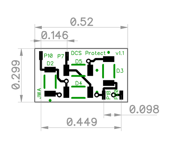
What do you mean Tom, they're huge! Over half an inch long and nearly .3" wide. ![]()
![]()
Attachments
Images (1)

Hmmm... I guess they are slightly larger than I was thinking, somewhat seeable at least. Can't wait to try the soldering part and trying to find the SMT components. ![]()
Just don't drop the resistors on a white floor. If they land upside down, you'll never find them, the white ceramic back blends right in! ![]()
The blue LEDs do that too! ![]() I have one missing here on the concrete basement floor, kind of white/light gray. Need to get my grandson over to find that one. I will watch out for the resistors, very carefully. I will probably be able to lose those resistors right on the workbench!
I have one missing here on the concrete basement floor, kind of white/light gray. Need to get my grandson over to find that one. I will watch out for the resistors, very carefully. I will probably be able to lose those resistors right on the workbench! ![]()
I hate to do this to you guys...… ![]()

I too have built it.... well, I have to plug in that main chip thing. Then I'll put it into one of my spare small project boxes to help it last.
I have to tune it. So now I need to go back and find the instructions on how to tune it up!
I read them here but like so many others that have replied, we've pushed the good stuff into the lost pile.
& Thank you Tom for the great kit..... (off to see if it works!)
Attachments
Images (1)
stan2004 posted:Here's one minimalist approach to "calibration" - no scope, no battery, no other components required! This uses the relatively accurate on-board 5V voltage as a reference.
With the 2 LED method (vs. original 1 LED method), there are 3 "zones". (1) BOTH LEDs blink meaning good signal level, (2) 1 LED blinks meaning marginal/degraded signal, (3) Neither LED blinks meaning very low or no signal.
1. Apply AC track voltage to module. Presumably the "Power" LED turns on. Use DC voltmeter to confirm you have 5.0V DC at the point indicated. The DC- side of the DC measurement is the circuit ground.
2. By momentarily touching +5V to the DC+ point as shown (using, say, an alligator jumper cable), you are effectively applying a 5V trigger. By turning the trimpot fully in one direction, you should be able to make BOTH LEDs flash each time you tap +5V to the DC+ point. By turning the trimpot fully in the other direction, you should not be able to make either LED flash. The idea is to adjust the trimpot to the case where you're at the threshold between NEITHER LED flashing and 1 LED flashing. To be clear, this is a separate threshold than between 1 LED flashing and BOTH LEDs flashing.
This simple (?) procedure "calibrates" the unit to flash both LEDs on a 10V DCS signal. This is probably good enough IMO but to each his own.
3. If you have access to a "known good" TIU channel, it will surely trigger BOTH LEDs as it appears you get more than a 10V DCS signal. You can then further adjust the trimpot with the "known good" TIU knowing that you have AT LEAST a 10V output. To do this, you then send a real DCS signal out the TIU and adjust the trimpot to the point where 1 LED flashes and BOTH LEDs flash.

here's what I need!
Just to be sure, the schematic does match Tom's board, right?
So the stripe on the diode at D1 to the R4 designation on the board at the pot?
Joe,
That looks great! GRJ and Stan have been further educating me here too (I'm a bit green on kit mailings). I am going to ask Stan if he minds me including his instructions and his picture showing component orientation in with the parts list. Also, you are most welcome, it's kind of fun. Hope it works out well for you and all your TIUs are healthy! (at least it looks like you got all the parts and they are still intact ![]() )
)
Engineer-Joe posted:stan2004 posted:Here's one minimalist approach to "calibration" - no scope, no battery, no other components required! This uses the relatively accurate on-board 5V voltage as a reference.
With the 2 LED method (vs. original 1 LED method), there are 3 "zones". (1) BOTH LEDs blink meaning good signal level, (2) 1 LED blinks meaning marginal/degraded signal, (3) Neither LED blinks meaning very low or no signal.
1. Apply AC track voltage to module. Presumably the "Power" LED turns on. Use DC voltmeter to confirm you have 5.0V DC at the point indicated. The DC- side of the DC measurement is the circuit ground.
2. By momentarily touching +5V to the DC+ point as shown (using, say, an alligator jumper cable), you are effectively applying a 5V trigger. By turning the trimpot fully in one direction, you should be able to make BOTH LEDs flash each time you tap +5V to the DC+ point. By turning the trimpot fully in the other direction, you should not be able to make either LED flash. The idea is to adjust the trimpot to the case where you're at the threshold between NEITHER LED flashing and 1 LED flashing. To be clear, this is a separate threshold than between 1 LED flashing and BOTH LEDs flashing.
This simple (?) procedure "calibrates" the unit to flash both LEDs on a 10V DCS signal. This is probably good enough IMO but to each his own.
3. If you have access to a "known good" TIU channel, it will surely trigger BOTH LEDs as it appears you get more than a 10V DCS signal. You can then further adjust the trimpot with the "known good" TIU knowing that you have AT LEAST a 10V output. To do this, you then send a real DCS signal out the TIU and adjust the trimpot to the point where 1 LED flashes and BOTH LEDs flash.
here's what I need!
Just to be sure, the schematic does match Tom's board, right?
So the stripe on the diode at D1 to the R4 designation on the board at the pot?
That's the current schematic and it should match any of the boards I did or all the ones that Tom has shipped. AFAIK, no changes have been made to my design since I posted the final version and bought the first ten boards.
Thanks GRJ. No disrespect on who's boards was meant.
Thanks Tom, it was a fun kit to put together.
===
1. Apply AC track voltage to module. Presumably the "Power" LED turns on. Use DC voltmeter to confirm you have 5.0V DC at the point indicated. The DC- side of the DC measurement is the circuit ground.
===
"AC Track voltage" means hook 18VAC up to the test board?
rtr12 posted:...I am going to ask Stan if he minds me including his instructions and his picture showing component orientation in with the parts list.
Anything you think would help is fine by me.
swise posted:… "AC Track voltage" means hook 18VAC up to the test board?
Yup.
Engineer-Joe posted:Thanks GRJ. No disrespect on who's boards was meant.
None taken, I was just clarifying that my original schematic is good for any boards currently in circulation. ![]()
Ok, I received my kit and build it. I am a little confused with Stan's calibration procedure. At the end he states with a good tiu adjust trim pot unit one LED flashes and BOTH Flash? What does that mean? I ASSUME it means you want to turn the pot Clockwise until the Green LED no longer flashes, and then back off some until it just begin to flash again with a known good TIU. This would mean anything less than the good TIU value would not flash the Green LED.
Also is the Pot a linear function on adjustment. For example, I have my good TIU with the POT flat around 1 O'clock. I can measure that resistance value. If I have a TIU that is at 11 O'clock to get both, can I use the resistance to figure out how much the signal is degraded via a ratio? Or is this a non linear function? Thanks to all that contributed to this. G
PS For my good TIU which is my bench SF Loader only, have only used Fix1 and it is a REV L, it turns out both Fix 1 and Fix2 have the exact same pot setting to get the green to light. Fix2 has never been used.
I would suggest to the people assembling this board to add some hot melt behind the pot to hold it firm. Mine bent over while trying to adjust it. I imagine the way it's shaped means it works better with certain screw tips?
I put it into a case so that I can take it outside easily.
I also didn't fully know how to calibrate so I did exactly the way G described above. We think the same!
Edit: BTW I think mine ended up around 11:00? I considered adding a momentary switch to jump the 5 volts for calibrating. What do you think??
I'm not sure what a known good channel would be around here! ![]() I think all mine are good but I haven't tested yet.
I think all mine are good but I haven't tested yet.
Edit#2: test used Channel 1 of the Z4000, connected to channel #1 Fixed on TIU #1, aux AC power wall wart connected to TIU.
Joe,
GRJ is correct, no changes have been made to his last original post above, of the TIU Tester schematics, PCB files and components. Nice video Joe! Looks like you are up and running.
Also, For everyone still on the list for a kit, the next couple batches of PCBs/kits will be the same as all have been so far. No changes.
Stan,
Thank You. As usual you have been a lot of help here.
GGG,
I haven't tried the calibration yet, just checked mine to see if it worked and it did. I have a big mess to clean up on my bench (part sorting with no previous place to put them) and I have been goofing off the last couple days. ![]() I imagine (hope) Stan will be back by to assist, he knows a lot more about it than I do as well.
I imagine (hope) Stan will be back by to assist, he knows a lot more about it than I do as well.
GGG posted:Ok, I received my kit and build it. I am a little confused with Stan's calibration procedure. At the end he states with a good tiu adjust trim pot unit one LED flashes and BOTH Flash? What does that mean? I ASSUME it means you want to turn the pot Clockwise until the Green LED no longer flashes, and then back off some until it just begin to flash again with a known good TIU. This would mean anything less than the good TIU value would not flash the Green LED.
Correct. The red LED should flash in each case. The earlier steps calibrate the green to trigger at 10V. The end step is to fine-tune to something more than 10V from a "known good" TIU channel which supposedly puts out a bit more.
GGG posted:...
Also is the Pot a linear function on adjustment. For example, I have my good TIU with the POT flat around 1 O'clock. I can measure that resistance value. If I have a TIU that is at 11 O'clock to get both, can I use the resistance to figure out how much the signal is degraded via a ratio? Or is this a non linear function?
The pot itself has a linear taper (vs. logarithmic/audio taper) so the resistance changes at a fixed rate. The math gets a bit complicated to do what I think you're inquiring about. But in a small region - like between 11 o'clock and 1 o'clock for example, I suppose you could make a table of Volts vs. Pot angle (or measured resistance).
Not having a unit, my opinion though is the ability to discern a threshold based on the flicker or flashing behavior is very subjective. I'd guess this alone could introduce 1 Volt or more of "error" in interpreting the result.
Engineer-Joe posted:...
Edit: BTW I think mine ended up around 11:00? I considered adding a momentary switch to jump the 5 volts for calibrating. What do you think??
Once calibrated you shouldn't have to touch the pot again given the intended go-maybe-no-go application. If you want to experiment with turning the pot to a different angle as a method to measure a slowly degrading voltage (like GGG is pondering), I suppose a momentary push-button would be a simple way to reset the threshold back to 10V.
The problem with hard and fast pot positions was covered by Stan a long time ago. The variability of the triggering of the 123 chip is significant, and it's trigger point is a key factor in the calibration. AAMMF, it's the reason for needing a calibration!
When we did the red/green indicator on the DM TMCC Buffer, we used 1% resistors and comparators. That gives you a repeatable (within a couple percent) trip point for the various indications. If this little board had used similar technology, it would not need calibration. However, in that case, it would have required more parts, something that was not desirable. ![]()
What I was trying to describe is my wondering if my known good channel of the TIU is actually good?
What if first I calibrated to a channel that was marginal and then checked all my other TIUs?
I did not do the 5 volt jump test first. I used a TIU channel that seems to work well.
I mentioned this before, but it needs to be stated again. This little tester ONLY works properly with a pure sine wave transformer feeding the TIU! I tried to use the Z1000 with the controller, and the red light is always on. When I look at the signal on the 'scope, it's obvious why, there is a big zit on the waveform that it triggering the 123.
Use a pure sinewave transformer, and you'll get the results you're looking for!
This may explain the Fix versus VAR when in fixed mode output. So if red stays on there is a distortion on the wave form? G
Perhaps, I tested a known good TIU (checked with my 'scope), and the variable channels (in fixed mode) tested just the same as the fixed channels.
Here's a test of the board using the Lionel 1033 to power the TIU, tester is connected to Variable #1 (in fixed voltage mode) to illustrate the variable channels work the same as the fixed channels.
Hi Guys.....
I'm a little unclear as to what the steps are for calibrating and using the TIU Tester. So, I took the comments and tried to consolidate them into a single document for calibrating and using the TIU Tester.
Would you please review and let me know if any of this not correct? I would be happy to update it and repost for anyone who wants to use it. This is what I came up with based on my understanding of the steps mentioned in the various posts:
1. Jumper the circuit board from +5v side to the DC+ side.
2. Apply 18 volts AC (using a full sine wave transformer (e.g. old Lionel transformer); NOT a modified or "chopped" sine wave transformer (e.g. MTH Z4000 transformer)) to the TIU Tester posts on the circuit board.
3. The "power" (Blue) LED should illuminate.
4. Adjusting the trip pot:
A. Start by turning and setting the trim pot fully in one direction to cause both the Red and Green
LEDs to flash.
B. Then turn the trim pot in the opposite direction (from above) to cause both the Red and Green
LEDs to not flash at all.
C. Finally, turn the trim pot from the point where the Red and Green LEDs are not flashing to the point
where only ONE LED is flashing (not sure if it matters which LED should be flashing?).
D. This procedure sets the tester (calibrates it) to detect a minimum 10 volt DCS "command" signal.
5. Remove the circuit board jumper.
6. Apply power to a TIU.
7. Before testing a TIU, set the TIU's Variable ports to "Fixed".
8. Connect the Tester's TIU output posts to one of the TIU channel outputs to be tested (does it matter which Tester post is connected to which TIU channel out; i.e. Red or Black?).
9. Press one of the "command" buttons on the TIU's remote (Whistle, Startup, Bell, etc.) to send a DCS signal.
10. Monitor the Red/Green LEDs on the Tester. When both LEDs flash, the TIU is sending out a DCS signal that's 10 volts or more. This indicates the TIU channel being tested is not damaged and is functioning as it should be. Anything else indicates the TIU channel may be damaged and in need of repair.
I'm not sure of the significance of the Red and Green LEDS. A lone Red LED flashing is a 5 volt or less DCS command signal? I don't know if a lone Green LEDflashing will ever occur?
Thanks!
A lone green LED can never occur, at least unless the test board is broken. ![]()
Thanks GRJ....I will add that note. Any thoughts on the other bolded questions I had?
If the crossover distortion on the Z4000 is triggering the one shot, you could try pushing the HPF corner frequency out further. Maybe try 1K or even 100 ohms for the shunt elements...
I haven't tried the Z4000, mine is packed up and on the bottom of a pile of boxes. ![]()
Adrian, wouldn't going as low as 100 ohms stomp on our signal a bit too much?
Junior posted:Thanks GRJ....I will add that note. Any thoughts on the other bolded questions I had?
The Hi post on the TIU connection is the red post, yes it does matter.
For the LED's flashing, if only one is flashing, it has to be the red one, the green one only flashes when there's more amplitude, and by definition, the red one is already flashing.
The applied AC voltage to the TIU is non-critical, my 1033 applies 16 volts maximum, works just fine. The AC voltage is really just to power the TIU and the test board, probably 12 VAC would do that just fine. The key requirement is a pure sine wave so you don't get noise artifacts through the filter to give false triggering.
gunrunnerjohn posted:I haven't tried the Z4000, mine is packed up and on the bottom of a pile of boxes.
Adrian, wouldn't going as low as 100 ohms stomp on our signal a bit too much?
0.1uF X 100 ohm is still a 100KHz cutoff well below the 0.7 to 5MHz DCS power spectral density. Should work ok I think.
I can’t check it right now though because I’m still trapped in nowheresville USA defending the NASA spacecraft from scorpions and coral snakes with a pointy stick ...
I can't do circuit design, PCB design or anything NASA related, but I could handle a pointy stick to fend off some snakes and scorpions for you, if that would help you get out of nowheresville USA any sooner. ![]()
Junior posted:
1. Jumper the circuit board from +5v side to the DC+ side.
4. Adjusting the trip pot:
A. Start by turning and setting the trim pot fully in one direction to cause both the Red and Green LEDs to flash when +5V is momentarily connected to DC+.
B. Then turn the trim pot in the opposite direction (from above) to cause both the Red and Green LEDs to not flash at all when +5V is momentarily connected to DC+.
C. Finally, turn the trim pot from the point where the Red and Green LEDs are not flashing to the point where only the Red LED is flashing when +5V is momentarily connected to DC+.
D. This procedure sets the tester (calibrates it) to detect a minimum 10 volt DCS "command" signal.
5. Remove the circuit board jumper.
It's a momentary connection between +5V and DC+ which should cause 0,1, or 2 LEDs to briefly flash. If 1 LED flashes, it well be the Red one.
Note above that engineer-joe is considering a momentary push-button switch to make this connection between +5V and DC+ to facilitate calibration. I had earlier suggested an alligator jumper cable - one side clipped to one side, and then the other side momentarily touched to the other side.
Thanks Stan, GRJ......I will make updates to the procedures as soon as I can.
I found time tonight to assemble the kit. I want to thank GRJ for designing the board in his usual excellent manner, and rtr12 for compiling the kit. Having color distinction problems, I really appreciated rtr12 marking the sets of resistors with their values. Saved me the problem of either asking Mrs RJR to tell me the colors, or pulling out my trusty Fluke.
Up in this thread is a picture of a board on which the author had superimposed indication of where the flat sides and white stripes go. Very helpful.
I plugged it into a Rev L Fixed circuit without calibrating, and fired up the layout. The red came on whenever I sent a signal, and the green rarely. What puzzled me is that when trains were running, both green & red would flicker periodically.
Now to read back through this thread to study calibration & operation.
As an aside, I have an occasional doubletoot problem with softkeys. I notice there was no flash before the second toot. After closing down, occurred to me that I can put it on the other TIU and see if there is crosstalk causing the 2nd TIU to also issue a signal.
GRJ & RTR12: Hope you guys produce more useful kits.
Question, would calibrating the unit on a Rev G or Rev H, which apparently didn't suffer from signal degradation, be satisfactory for use on a Rev L?
RJR posted:...I plugged it into a Rev L Fixed circuit without calibrating, and fired up the layout. The red came on whenever I sent a signal, and the green rarely. What puzzled me is that when trains were running, both green & red would flicker periodically.
Apparently you're attached to a powered layout with engine(s). This is not the intended application of the simple tester. The DCS signal voltage at the TIU output drops as soon as you load it with your layout and engine(s). The simple tester is meant to measure the DCS signal level with nothing loading the TIU output.
Both LEDs a re flickering with running trains because of occasional transients typically from dirty track or momentary loss of roller-to-track contact. These transients are typically 30 Volts or more and hence large enough to trigger the simple tester.
I did not realize that Stan! I thought of that first. I wondered what the TIU and remote would do when no engine was on the track (and no track).
I thought you needed an engine to have the TIU to "talk to". I guessed wrong again.
From force of habit, I started trains to send signals to. Appears the TIU tester can also serve to indicate tracks needing to be cleaned.
I have a REV H I use for Test bench testing. It had the same calibrated output (FIX1 and 2 only) as my REV L. It is an old damaged TIU (Bad VAR1 and 2) but it had strong output on F1/2. If you go to my test result post, you will see that how the TIU is powered (F1 or Aux Port) matters on how the LED respond.
If the TIU is only powered by F1 at startup of the tester, the LED Stay solid for a period. This lead me to think a strong DC Signal is present. So I measured this with a basic VM, and at TIU start up I got a 50-60mvdc output that would go down after the LED started to flash. This was repeatable on all channels, even tried the rev H which read at the higher end.
So next bad TIU I get I am going to see if this DC Signal at startup can also be used for a basic correlation of signal strength. G
Add Reply
Sign In To Reply
