
The final solution, forget the stuff below!

****************************************************************

Edit:  This is a link to the latest and greatest version with the 555 timer that requires no calibration.

Build files for 555 timer version

****************************************************************

*** Back to our regularly scheduled discussion. ***

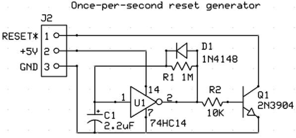
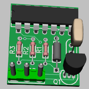
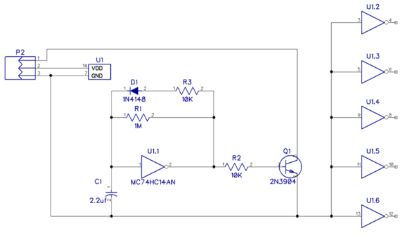
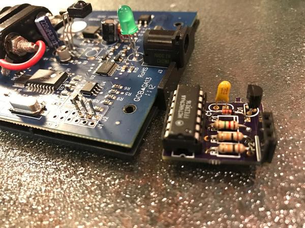
This is the what we finally came up with.  It's a small add-in board to a DCS Remote Commander that turns the DCS-RC into a continuous watchdog generator.  It plugs into some pins we add to the PCB.

DCS-RC Watchdog Reset Generator Thru-Hole Gerber Files.zip

================================================================================

Where we started

================================================================================

I'm working on coming up with a solution for some yard track at our club, we have several sets of tracks that we'd like to get DCS working on.  We have a rotary switch to select one of "n" tracks to power at a time, so I came up with this scheme.

We will be using a separate TIU channel for this task, and it'll be used in passive mode.  The yard power comes through a high-current 22uh choke to avoid any issues with crosstalk with the DCS signal on the mainline.  Operation is as follows.

Starting with the Track Selector off, no power to the TIU channel or tracks.  Switch is rotated to the correct track, the relay is energized, and that track is connected to the TIU channel output.  This results in the DCS signal becoming active and emitting the watchdog.  The plan is to keep the engine silent until it's started up.

See any issue with the idea?  Got any suggestions to improve on it?

Switch Yard DCS Signal Manager

Attachments

Last edited by gunrunnerjohn
Original Post

Replies sorted oldest to newest

I was wondering if the system would find an added TIU after the initial power up.

Absolutely. Any remote can access any TIU in the remote's TIU list any time that both are powered on, regardless of whether the remote was on or off when the TIU was turned on. Remotes initiate conversations with TIUs, not the other way around.

John, before DCS was released I had that problem while learning the system.  I have my big yard with 23 tracks and my turntable with 40 tracks.   On my big yard each track was controlled with toggle switches.  On the 40 tracks at the turntable, control was done with rotary switches.  I ended up adding a common buss wire to all track grounds.  I immediately got a 10 signal.  I have that same 10 signal today.  People have had success with lighted bumpers.  As we know, yard tracks and sidings can be tricky.  I know Barry has lighted bumpers and has success with them.  Being a toy train guy, I love the look of the postwar red lighted bumper.  I may put them on yet and wire the center rail contact from another power source.  I was thinking a rail cut in front of the bumper and wire the end of the track with wires soldered to them.  The look of 23 lighted bumpers will please this toy train guy.

Last edited by Marty Fitzhenry

John,

There's a non-wiring method to having any MTH engine (or lashup!) come up dark and silent on any powered track after the watchdog signal has come and gone.

From page 105 of The DCS Companion 3rd Edition:

If a lashup is powered on after the watchdog signal has come and gone, perhaps if its siding was toggled on after voltage appeared at the TIU channel outputs connected to its siding, there are two ways to put the lashup into DCS mode. One way to put the lashup into DCS mode is to turn off power to the inputs for the TIU channel that is connected to the track upon which the lashup resides, toggle on the siding and then re-apply power. The other way is to first highlight the lashup in the remote's Active or Inactive Engine list. Then, flip the toggle switch and immediately press the thumbwheel to select the lashup. It will come up in DCS stealth mode, dark and silent. This also works with individual DCS engines.


DCS Book CoverThis and a whole lot more is all in “The DCS Companion 3rd Edition!"

This book is available from many fine OGR advertisers and forum sponsors, or as an eBook or a printed book at OGR’s web store!
Barry Broskowitz posted:
The other way is to first highlight the lashup in the remote's Active or Inactive Engine list. Then, flip the toggle switch and immediately press the thumbwheel to select the lashup. It will come up in DCS stealth mode, dark and silent. This also works with individual DCS engines.

Some of the club members are barely able to run the engines using DCS, I don't think a little rain-dance of synchronizing the power on the tracks and the remote is going to fly.  For about $3 in parts, I can make this appear seamless without any special knowledge by the users.

rtr12 posted:

Isn't passive mode connecting to the output only? I was thinking (probably incorrectly?) that the TIU had to see power on the input before it would send the DCS signal? I have never tried passive mode or super TIU mode either for that matter.

Works fine when the voltage is on the output, try it.

 Barry Broskowitz posted:

John,

Whatever.

It's not "rocket science", it costs nothing and it takes no particular skill to implement. To me, that's the definition of a good solution.

 That's your definition of a good solution. 

Pretty presumptuous of you to assume that you know better what will work for us in our situation.  Operationally, people that come in on visitor's days will find it much easier to live with my solution, it doesn't take any extra knowledge or extra keystrokes and synchronization.  They just turn on the track they're staged on and start up and drive out.  To me, that's the definition of a good solution.  Since I get to define the solution for my circumstances, that happens to be the definition of a good solution in this case.

Last edited by gunrunnerjohn
gunrunnerjohn posted:

...

We will be using a separate TIU channel for this task, and it'll be used in passive mode.  The yard power comes through a high-current 22uh choke to avoid any issues with crosstalk with the DCS signal on the mainline. 

If the 22uH is to the left of the diagram (off the page) wouldn't the relay capacitor degrade the DCS signal on the selected track?

If I understand the operation, when changing from one track to another, the user must first rotate back to the "OFF" position.  And when selecting the new track, the user must rotate the knob to the desired position within whatever the interval (a few seconds?) during which the TIU sends the watchdog after power up. 

And if lighted passenger cars are on a siding, they will briefly flash as the rotary passes by.

Does the typical individual toggle switch approach present a space issue?

As discussed in the contemporaneous thread about the DCS watchdog using rotary switch for turntable power, in some situations it can make sense to add complexity to make it simple for the end-user.

OK, understood we're talking about an add-on.

So is there a visual indicator of which siding has power?  Lighted bumper, control panel LED, etc?

I'm still curious about having to first return to the "OFF" position when changing active track.   The club guys will learn by experience but I'm thinking about your visitor day scenario.  The approach in the other thread uses a relay-per-track which is not a drop-in mod for your configuration.  But what about "automating" just that single relay that toggles power to the passive-mode TIU output?  In other words whenever and while the rotary changes position, it disables the relay and then re-enables it after the rotary has settled on the new position.  I'm not saying it's a simple circuit but more in the spirit of a discussion about dealing with what appears to be more than a one-off.

Yep, each yard track has a lighted bumper at the end.  I thought about a more exotic solution, but in the end simplicity won out in my thinking.

Right now I'm looking at a handful of diodes, a choke, a capacitor, a resistor, and the relay.  In addition, I don't have to hack any of the existing wiring, just tap into it.  I'll be able to assemble this all on a small board and just stick it under the layout at the control panel where all that wiring is already available.

I can visualize how your solution would work, but it would be more work.  I believe I'd also have to hold off the power to the track as well as the TIU channel. A brief power interruption of the TIU channel probably wouldn't be enough to trigger the watchdog output.  I'd also have to add some logic to know when the switch transitions take place to control the action.  Not difficult, just more parts, and more work.

John,

That's your definition of a good solution. 

Yes, it was. Be careful when you scratch an itch - you'll make that thin skin of yours bleed all over the place.

Regardless, have you thought about just hooking up a DCS Remote Commander in Passive mode so that when you select a siding with your selector switch, the DCS Commander receiver emits the watchdog signal?

The receiver is less expensive than a TIU and, unlike the TIU, there's no Aux. Power requirement. This solution should be just as simple as yours only less expensive and a bit less work to implement.

BTW, it's on page 206 of The DCS Companion 3rd Edition.


DCS Book CoverThis and a whole lot more is all in “The DCS Companion 3rd Edition!"

This book is available from many fine OGR advertisers and forum sponsors, or as an eBook or a printed book at OGR’s web store!
Last edited by Barry Broskowitz

This is an "ignore the man behind the curtain" situation. 

If you accept the procedure of rotating the switch to the "OFF" position for a few seconds every time you want to change the active siding then so be it.  A possible benefit of Barry's suggestion to use the DCSRC would be have your lighted bumpers remain on while the man-behind-the-curtain (i.e., the DCSRC) is momentary attached to the yard power for the purpose of generating the watchdog to silence the new track.  Otherwise the lighted bumper on the new active track would turn off during the interval when power is removed from TIU.  I'm not sure that's what Barry had in mind but I figure he was proposing the DCSRC in addition to the existing passive-mode TIU which you'd obviously need to control your engines.

Anyway, I guess simplicity wins out.  I was thinking it could be done with a bunch of capacitors to detect a change in the switch position and a 555-timer chip to detach the relay for a couple seconds to cycle power to the passive TIU.  But during this interval the lighted bumper would turn off which could be confusing to the casual user if the lighted bumper is the only indicator of the active siding.

As always, I'm here to save the day with more complex solutions!  How about that relay board- arduino combo from the other thread?  I'm unsure of your exact set-up, but if it would be useful to ever have more than one of the side tracks turned on at the same time, I would go with the remote commander to produce a watchdog signal.   In either case, one relay on the board can be used to turn on and off the remote commander, or input to the TIU, and the rest to supply power to the sidings.  

A simple sketch on an arduino could be programed to cycle TIU/Remote Commander on and off every time a new siding is switched on.  It's, of course, more complex than your solution, GRJ, but it would allow switching between tracks without having to go back to zero every time.  


As a side note, perhaps those that can bend the right ears at MTH might consider suggesting a firmware update that would allow some signal to be sent in on the serial port that tells the TIU to send out a watchdog signal.   Perhaps even as an add-on box that plugs into the TIU and has an input side so that whenever the input is turned off then on again the TIU would broadcast the watchdog.  this would solve everyone's problems with switched sidings, and I'm somewhat surprised that some method for users to trigger a watchdog without reseting a channel was not added years ago.  

JGL

stan2004 posted:
I'm not sure that's what Barry had in mind but I figure he was proposing the DCSRC in addition to the existing passive-mode TIU which you'd obviously need to control your engines.

That's the only way I could see it working, and I can't see having another box in the picture when I have one that is perfectly capable of generating a watchdog.

stan2004 posted:
Anyway, I guess simplicity wins out.  I was thinking it could be done with a bunch of capacitors to detect a change in the switch position and a 555-timer chip to detach the relay for a couple seconds to cycle power to the passive TIU.  But during this interval the lighted bumper would turn off which could be confusing to the casual user if the lighted bumper is the only indicator of the active siding.

I think in this case, I'll go with simplicity.  If they can't live with turning off the sidings when starting up a DCS locomotive, they'll have to add it while it's idling on the tracks.

JohnGaltLine posted:

As always, I'm here to save the day with more complex solutions!

We could debate the "saving the day" part...

JohnGaltLine posted:

As always, I'm here to save the day with more complex solutions!  How about that relay board- arduino combo from the other thread?  I'm unsure of your exact set-up, but if it would be useful to ever have more than one of the side tracks turned on at the same time, I would go with the remote commander to produce a watchdog signal.   In either case, one relay on the board can be used to turn on and off the remote commander, or input to the TIU, and the rest to supply power to the sidings.  

L

Yikes!  Introducing that much extra work isn't in my game plan!  You obviously missed my signature line!

Nothing is so easy as the job you imagine someone else doing.

JohnGaltLine posted:
As a side note, perhaps those that can bend the right ears at MTH might consider suggesting a firmware update that would allow some signal to be sent in on the serial port that tells the TIU to send out a watchdog signal.   Perhaps even as an add-on box that plugs into the TIU and has an input side so that whenever the input is turned off then on again the TIU would broadcast the watchdog.  this would solve everyone's problems with switched sidings, and I'm somewhat surprised that some method for users to trigger a watchdog without reseting a channel was not added years ago.

Can't argue that would be useful for a lot of folks, but I don't see it happening any time soon.  Maybe this is a product idea.

Remember that you did ask for suggestions!

In the "other" thread, PLCProf proposed a touch-sensor detector or something like that to momentarily activate the relay whenever someone hand touched the control knob.  That would involve some circuitry so I guess it was voted off the island.  But remember the QSI motion sensor for the cattle-car sound cars?  It was a simple but ingenious idea to detect motion.

Untitled

If something like that could be attached to the shaft or any moving part of the rotary switch, it could trigger a timer (homebrew 555 or a $1-2 eBay module ) which would momentarily drive the new relay to remove track power from the passive-TIU.

It would be a simple job since I am indeed imagining you doing it. 


Attachments

Images (1)
  • Untitled
Last edited by stan2004

Sure, envision connecting two DCS channels to the same track, that's crosstalk.  That happens as you cross channel boundaries, but having them connected all the time would play havoc with the DCS signals.  The 22uh chokes are to prevent that from happening.  Since one ZW is powering all the yards I'm working on, without the chokes we'd have problems.

John,

Sure, envision connecting two DCS channels to the same track, that's crosstalk.

No, not at all.

You would use the TIU channel that powers the mainline to which the sidings connect as your "Yard Power". As soon as the connection is made, the engine gets a watchdog from the DCSRC receiver and then is controlled from the DCS Remote using the TIU channel of the main line.

Barry Broskowitz posted:

John,

The DSCRC receiver simply replaces the passive mode TIU channel, without the need for an Aux. Power connection.

If the passive mode TIU channel works, then the DCSRC receiver will work, as well.

Really?  So I can use the DCS remote with the DCSRC?  I'll bet that's news to MTH.

Remember, I'm using the TIU already to provide DCS to the tracks.  The TIU does just a bit more than the DCSRC, which won't work in my scenario.

As far as using the mainline signal in the yard, we've already tried that, and the signal isn't sufficient to offer reliable running.

Last edited by gunrunnerjohn

John,

Really?  So I can use the DCS remote with the DCSRC?  I'll bet that's news to MTH.

The two interoperate, connected to the same tracks, absolutely perfectly without any issues at all.

I'm using the TIU already to provide DCS to the tracks.  The TIU does just a bit more than the DCSRC, which won't work in my scenario.

The DCSRC receiver replaces the additional TIU that you're using in your solution, but only to generate a watchdog signal. The mainline TIU (or some other TIU already own the layout) is what would provide the ability to control the engines.

As far as using the mainline signal in the yard, we've already tried that, and the signal isn't sufficient to offer reliable running.

I'd suggest that tweaking the layout a bit to improve the DCS signal distribution could make using the DCSRC receiver and the mainline TIU work just fine as a solution. Regardless, assuming that you're operating in  Super TIU mode, you could use any channel on any TIU that has available extra DCS signal capacity. You don't need much DCS capacity, only enough to handle a single siding at a time.

Regardless, rest assured that there is absolutely no difficulty or operational issue with connecting a DCSRC receiver to the same track as a TIU channel, and even with each operating engines simultaneously. Been there, done that and got the T-shirt.  

Anyways, use my solution or not. I offer it in the spirit of assistance. Good luck whatever direction you choose.

Last edited by Barry Broskowitz

Here's the fix.... Assign a shop  foreman (experienced dcs user)  with his own remote who get the engines ready to leave the shop on the outbound shop track.  He now  hands over the engine to a club member .  ID  to same ID.  He's also responsible for putting engine away when  they arrive.  

Barry where do you  get the T-shirt?

gunrunnerjohn posted:

Sure, envision connecting two DCS channels to the same track, that's crosstalk.  That happens as you cross channel boundaries, but having them connected all the time would play havoc with the DCS signals.  The 22uh chokes are to prevent that from happening.  Since one ZW is powering all the yards I'm working on, without the chokes we'd have problems.

How could you have crosstalk when the DCSRC is only being used to generate a watchdog signal?

I've been using a DCSRC to generate the watchdog signal on a unpowered siding where locos are parked for a few years now with no problems. Siding is wired thru a toggle switch that connects it to the mainline. DCSRC is wired to siding in passive mode. Throw toggle to power siding on, watchdog signal is generated, start loco and run out onto main.

Talking about the DCSRC...didn't I read somewhere that it will be updated to run any loco regardless of address? 

Casey Jones2 posted:

How could you have crosstalk when the DCSRC is only being used to generate a watchdog signal?

Casey, you need to go back and read the original post.  I'm using a TIU channel to provide the watchdog and the DCS signal in the yard.  Barry brought up the DCSRC later in the discussion.  If you connect two DCS channels together, you will have problems.

Casey Jones2 posted:
Talking about the DCSRC...didn't I read somewhere that it will be updated to run any loco regardless of address? 

Are you sure you're not thinking of the feature on new PS/3 engines that allows you to set them to factory defaults using the DCSRC?  I've heard nothing about making the DCSRC universal, and I seriously doubt that will happen.

gunrunnerjohn posted:

...We have a rotary switch to select one of "n" tracks to power at a time

Is it a break-before-make?  I'm still fixated on eliminating the need to first go to the home/off position whenever changing active track!

As a general question to anyone who uses rotary switches to distribute track power to 1-of-many (roundhouse, yards, etc.) under what circumstances would you want a make-before-break switch...thereby powering up (albeit momentarily) two tracks at the same time?

Don't know if this helps or not but, all the tracks in our engine terminal have a toggle switch for each individual track. Generally, the toggle switches are always "OFF". When a DCS equipped locomotive is powered up, by flipping the toggle switch to "ON", the model first powers up in "conventional" mode, however by simply selecting THAT model in a DCS hand-held, and then pressing "START UP", the model then is in "DCS MODE", and ready to be operated with the DCS hand-held. Seems to work pretty consistent for us.

gunrunnerjohn posted:

I know I can do that, the object of the exercise is for the engines to come up dark.

OK, then I'm obviously confused,,,,again. I am under the impression that the "Watchdog Timer" signal is ONLY issued/transmitted when the TIU is first powered up. Thus, any and all DCS models sitting around on "live/powered" tracks, receive the "Watchdog Timer" and come up dark. Correct?

Hot- the watch dog goes out each time the voltage is raised above 0 on any channel.

The problem is that any toggled off siding will miss  the watch dog.. not a big deal for most.

As I mentioned I like to have a toggle on the input side  of the tiu  as well as the output just in case  it's needed as in  starting a lash-up  . (MU)

Last edited by Gregg

Gregg,

the watch dog goes out each time the voltage is raised above 0 on any channel.

Actually, the watch dog is issued any time the voltage at a TIU channel output port changes from 0 to any greater value. That's why the watchdog can be issued in passive TIU mode.


DCS Book CoverThis and a whole lot more is all in “The DCS Companion 3rd Edition!"

This book is available from many fine OGR advertisers and forum sponsors, or as an eBook or a printed book at OGR’s web store!

OK, so I'll reword the question:  why is the watchdog limited to 45 seconds, rather than being left on?

ANother question, which is relevant to GRJ's scenario, is how long must the power to a channel be off before turning it on will re-trigger a watchdog?

GRJ:  I would not that your solution does not account for the wifi, which, unless the app is left on from the last session, has to read the layout each time a loco is newly-started.

Barry,

i am electronics challenged but i will try and ask this correctly... if gunrunner john or myself uses a separate tiu we have in passive mode and use the DCS remote commander when power is applied to the yard tracks after rest of layout has been powered up that the tiu in passive mode and DCSRC is used then the engines will remain silent or did I miss something?

or do you mean wiring power to each yard track from an existing tiu and then using the DCS remote commander it the remote commander supplies the watchdog signal and engines will remain silent?

now how does this RC thing send watchdog signal? 

gunrunnerjohn,

correct me please electronics challenged I am!  if I understand you are making a PCB with some electronic items that will delay the power to a yard track when the toggle switch is set to on so the tiu and track thinks its being powered up just like mainline tiu's do and all tracks see the watchdog signal?

how close am i to understanding this?

gunrunnerjohn posted:
stan2004 posted:

I'm still fixated on eliminating the need to first go to the home/off position whenever changing active track!

I can see that Stan!

Ok, I admit I'm not close to being an expert on DCS or layout wiring, but would it be possible to put a toggle in place of the capacitor before the selector switch?  It changes the behavior slightly in that you would select the track, flip the toggle on, operate the locomotive(s), then when finished, toggle off, switch to the next track, power on, and so on.   If it works this way, sign me up.


RJR posted:
GRJ:  I would not that your solution does not account for the wifi, which, unless the app is left on from the last session, has to read the layout each time a loco is newly-started.

Correct, no plans for adding WiFi to this mix.

StPaul posted:

i am electronics challenged but i will try and ask this correctly... if gunrunner john or myself uses a separate tiu we have in passive mode and use the DCS remote commander when power is applied to the yard tracks after rest of layout has been powered up that the tiu in passive mode and DCSRC is used then the engines will remain silent or did I miss something?

If you have a separate TIU in passive mode, which is what I'm doing, you don't need the DCSRC, the TIU will do the job just fine.  Barry was suggesting using the mainline DCS signal and just generating the watchdog with the DCSRC, however we're using the separate TIU.

Ironhorseman posted:

Ok, I admit I'm not close to being an expert on DCS or layout wiring, but would it be possible to put a toggle in place of the capacitor before the selector switch?  It changes the behavior slightly in that you would select the track, flip the toggle on, operate the locomotive(s), then when finished, toggle off, switch to the next track, power on, and so on.   If it works this way, sign me up.

You could, of course, use a toggle switch before the selector switch to interrupt the power, obviously that would work.  Stan wants to automate it so you just pick a track and everything happens behind the curtain.

gunrunnerjohn posted:

...Stan wants to automate it so you just pick a track and everything happens behind the curtain.

I'm still on the case.  RJR's comments about watchdog timing got me thinking.  Like he says, why not have the watchdog in the yard on all the time?  So my latest scheme:

Use a DCSRC passive-mode powered by a relay that continuously turns on and off once per second (using a homebrew 555 timer or an eBay cycle-timing module for $1-2).  I just checked and a DCSRC will generate a watchdog after a power interruption of a fraction of a second.  This will put a watchdog signal on the track once per second whenever there is yard power. 

Now you can rotate the selector switch directly to the desired track without first going to the off/home position.  And within one second, the newly powered track will get a watchdog signal and the engine will come up silent in command-mode.

The bonus of this approach is the track bumper LED that indicates to the user which track is active never blinks OFF as it would for any scheme that momentarily cycles track power to a passive-mode TIU.

Last edited by stan2004

I switch on the track(s) in the yard I plan to use before firing it all up.  The locomotives then catch the signal, although locomotives are not supposed to be stored in the freight yard! The Super gets her dander up if we don't "follow the rules" on the CL&W.  Being a non-complicated kind of guy I've chosen the simplest method which proves to work, by trial and error. FINALLY got the layout working the way I want so we stopped upgrading and improving; left DCS at the last release I could get to load properly; same with TMCC.

No budget for going to Legacy, but as we don't have any Legacy equipment ... all continues to work with "regular" TMCC.

Budget for new locomotives was frozen in favor of a locomotive repair fun, which is keeping even for now.

I have "blocks" that are controlled by an Atlas Selectors.  I simply: The power is turned ON everywhere for the TIU at the initial start-up so that the TIU can "recognize" all DCS command engines.  I then "kill" the power to each DCS engine on a particular track(s) via specific Atlas Selector toggle switch.  When I re-power later, the DCS engine automatically starts up after first contact with power.  I shut the engine down via remote ("6") and restart (#3).  I'm at the beginning.  Easy.

I started doing this because I'm tired of occasionally an engine will start itself and crash into the turntable (or worse) and I won't realize it happened until how much later?  One time I found an engine spinning its wheels against the outside of the turntable bridge--NOT GOOD.  Turning the power off to tracks DCS engines occupy after initial start-up PROTECTS from unwanted start-ups and worse--derailments.  Works like a charm!

I've never heard of a TIU recognizing command engines.  It just sends a command as directed by the remote to a loco that has already been added to the remote.

Unless one of my grandkids has pressed READ, all of my DCS locos are on the active list in the remote and, if on a powered track, will immediately respond to the startup command, whether or not they were on a powered track when TIU was turned on.

I realize this is over the top but I'll document it here anyway for future reference.  This is a refinement to my initial idea of a cycling relay to perpetually turn on/off a DCSRC once per second.  This would generate a DCS watchdog signal that would always be available to a yard siding or round-table spoke that was turned on with track power from an already active TIU output channel (so no watchdog).

The refinement was to recognize that the DCSRC uses a microprocessor chip inside.  And virtually all microprocessor chips have a signal input that will reset/restart/reboot the program.  So rather than an electro-mechanical relay perpetually clicking, why not generate an electronic signal to reset the microprocessor once per second.   Without getting into arcane details, the relevant signals in the DCSRC are conveniently available on a connector.  So by simply installing 3 pin on this connector, a circuit can be added which resets the processor chip once per second.

The 3 pins are +5V, Ground, and the Reset signal.  The 5V circuit is about $1 in readily available commodity parts and generates a narrow pulse about once per second which then resets the processor chip once per second.  The DCSRC appears to generate the watchdog about 3/4 sec after a reset.  Note that the modification is "additive" in that signal traces or components on the DCSRC itself are not modified, removed, etc.  So simply popping off the circuit board restores the DCSRC to its native function.

Perpetual watchdog generator using a DCSRC

And here it is in action.

The green LED on the DCSRC briefly blinks off on each reset but it does not show up in the video.  The video shows track power with a perpetual watchdog (provided by the modified DCSRC) applied to a track with a PS2 engine; you can see the lock-on light turn on and hear the engine's relay click on when power is applied.  In each case the engine starts up silent (in command mode).  Then the perpetual watchdog is remove.  Now when power is applied the engine starts up in conventional since there's no watchdog.  And in this example, the engine happened to be locked in conventional forward so it starts moving illustrating the undesirable scenario described earlier and in other threads.

So now the configuration would be:

dcs perpetual watchdog generator

So this is just another alternative to the methods already described.

It is surely more complicated to implement though arguably easier for the end-user to operate.  Like comparing manual vs. automatic transmission, the clutch is an added step for the end-user.  The automatic transmission makes it easier for the end-user but is a more complex mechanism.  I compare the clutch to the extra step of toggling an extra on-off switch to cycle power to the TIU/DCSRC or having to first return the rotary switch to the home/off position. 


Attachments

Images (2)
  • Perpetual watchdog generator using a DCSRC
  • dcs perpetual watchdog generator

Well Stan, between you, John, Dale and a hand full of others on this forum you continue to come up with these awesome ideas to bring this hobby into the modern age of electronic gadgetry. You certainly have my attention with this one. So, how does one go about acquiring on of these reset generators?  

Milwrd

Last edited by milwrd

That's a pretty cool idea Stan.  Any reason you didn't go for more than one second for the watchdog signal?  It does seem to work fine with one second, just wondered if perhaps two seconds would give a better window for certain success.

Apparently that 6-pin connection on the DCSRC is for the programmer to update the processor code, I wonder why the convenient 3-pin connector with just the right signals?

"Look closely, Stan hand built that one on a piece of perf-board.   Looks like it would be pretty easy to lay out one on a PCB, but I doubt there would be enough interest to warrant the expense of making the boards."

Hey Stan, is possible to get a few more pics of that board, especially the bottom? The schematic is plain and simple enough but it would clear up any misconceptions I have. Besides the wife hates the smell when I fry some electronic goodies.

Milwrd

That is very interesting Stan. I just happen to have a couple of those DCSRC devices left over from a couple of MTH sets. I might have to make use of them with your neat project here. Thanks for "staying on the case" and posting the results. 

And... thanks to one of your previous posts I might even have the 74HC14, in addition to all the other parts. That part sounds familiar, no doubt from one of you and GRJ's other electronics threads (which, after reading, I secretly order parts from). 

Last edited by rtr12
milwrd posted:

...Hey Stan, is possible to get a few more pics of that board, especially the bottom?

I wanted the board to fit inside the DCSRC (and be able put the case top back on) so started with a minimal sized perf-board of about 3/4" x 3/4".  In retrospect, the board area could be several times larger and still fit; a larger board ought to make it easier to assemble.  I took advantage of so-called pin-sockets for the IC chip though most guys don't have these and they are rather expensive (maybe 25 cents each) if you don't have a stash of them; considering the minimal cost of the IC chip (10 pieces for 99 cents on eBay, free shipping from Asia).   BTW note the 74HC14 chip in the photo is date-coded 8607...so that's from 1986 and of course Motorola (bat-wing M logo) is no longer in the chip business!

dcs pwgen 1dcs pwgen 2dcs pwgen 3


Attachments

Images (3)
  • dcs pwgen 1
  • dcs pwgen 2
  • dcs pwgen 3

Here you go, a board that will easily fit inside the DCS-RC.  The header is on the reverse side and the board projects out similar to Stan's board, just a bit smaller.  Yes, it's all surface mount, but I used larger footprint components to make it fairly easy to solder.  There was no model for the diode in the 3D library, so that didn't render on the 3D view.  The pins on the back side are arranged so the circuit board is over the components on the DCS-RC.  There are no components on the bottom.


Updated schematic and layout for more compact parts.

Attachments

Images (4)
  • blobid0
  • blobid0
  • blobid1
  • blobid1
Last edited by gunrunnerjohn
gunrunnerjohn posted:

That's a pretty cool idea Stan.  Any reason you didn't go for more than one second for the watchdog signal?  It does seem to work fine with one second, just wondered if perhaps two seconds would give a better window for certain success.

Apparently that 6-pin connection on the DCSRC is for the programmer to update the processor code, I wonder why the convenient 3-pin connector with just the right signals?

I might be misunderstanding your first question but to improve the chances of success, I'd think a shorter duration between watchdogs is desirable.  By experimentation I noted the DCSRC generates the watchdog about 3/4 sec after it receives power (or after it resets/restarts).  Then it goes silent not generating any further watchdogs.  So I figured the idea would be to restart the microprocessor after 1 sec (or so) to create the 24/7 "perpetual" watchdog.  Stated differently, I see no way to generate watchdogs more frequently than every 3/4 sec since it appears that's how long the DCSRC needs to generate the one-time watchdog under normal operation.

There are 2 un-populated connectors (J1 and J2) on the DCSRC board.  This gets into the arcane but the board uses a PIC processor chip which as you point is essentially a sure-fire indicator that one of those connectors (J2 as it turned out) would have the standard Microchip programming pin-out of Reset*, +5V, and Ground in that order.  Only the first 3 pins of the J2 connector were needed for this; hence you'll note I used "J2" as the reference designator for the 3-pin connection to the DCSRC board!

gunrunnerjohn posted:

...My point is the watchdog lasts for many seconds, so leaving it on for a few seconds has a longer duration watchdog available to the track, or to state it differently, the watchdog has a longer duty cycle.

Now I see your point.  But isn't that longer watchdog for the TIU (and not the DCSRC)?  Some of the earlier postings refer to a 45 second TIU watchdog interval which seems amazingly long.  I thought it was only a few seconds.  Anyway, I guess I wasn't looking for it but I didn't see any watchdog activity on the oscilloscope from the DCSRC after 1 second.  But you are correct that if in fact the DCSRC watchdog barks for more than 1 second, it would make sense to extend the interval.  The neat thing is the same circuit would work; simply change C1 from 2.2uF to, say, 4.7uF which would effectively double the interval to ~2 seconds.  Good observation!

gunrunnerjohn posted:

Here you go, a board that will easily fit inside the DCS-RC. 

LOL, I'm thinking Lucy holding the football for Charlie Brown!   I do marvel how quickly you can crank out the PCB designs!

When I started to prototype it I was going to use surface mount parts but figured it would be easier to make changes using through-hole parts.  If SOT-23 is a "larger" footprint component, why not the SOT23-6 version of the HC14?  

sot236


Attachments

Images (1)
  • sot236
stan2004 posted:
gunrunnerjohn posted:

Here you go, a board that will easily fit inside the DCS-RC. 

LOL, I'm thinking Lucy holding the football for Charlie Brown!   I do marvel how quickly you can crank out the PCB designs!

When I started to prototype it I was going to use surface mount parts but figured it would be easier to make changes using through-hole parts.  If SOT-23 is a "larger" footprint component, why not the SOT23-6 version of the HC14?  

sot236


A good point Stan, I could obviously change to that part.  For multi-pin parts, I try to stay with at least 1.27mm spacing on the leads.  .95mm probably isn't that bad.  It was so small with the full sized part that I didn't bother to look for the alternative.

Note that the three leads of the SOT-23 have wider lead spacing so soldering the individual leads isn't that challenging.  It's when you get fine pitch leads all together that it gets tricky.

So I have a bit of a question here...

We know that MTH chose not to have the TIU (or DCSRC) repeat the watchdog constantly, which would have eliminated the need for this fix in the first place.  Do you guys think it might be that the extra 'traffic' of this signal would reduce the effective bandwidth on the signal for other commands, and if so, will supplying a cycling watchdog, as this project is doing, cause any problems with the over-all signal on the layout?  I'm picturing it being a case where it wouldn't be a big deal normally to have two commands sent out from different sources , but with data constantly being sent from one point, will it affect the reliability of signals from a second source?  

I guess this comes back to the idea that there must have been some reason that the designers chose not to have the TIU provide a watchdog at a regular interval, and the only ones I can come up with are that:  1, the electronics used couldn't keep up with that on top of all the other functions, 2, the watchdog would interfere with the system in some way (using too much bandwidth), or 3, a lack of foresight that users might want to power up an engine after the layout has been powered.  If it is the last, though, I would think it would have been changed in a firmware update by now.  

Anyway, I guess this will mostly go to Stan for now, with the DCSRC cycling, do you experience any problems with other DCS functions?  

JGL

My guess is it's a fairly simple signal, but rolling a circuit to generate a modulated 3.27mhz signal would probably be quite a bit harder than spending $25-30 on the DCS-RC which already knows how to generate the signal.

JGL, in my case, the watchdog signal is just impressed on the yard tracks, so it's a moot point as far as bandwidth.  As soon as you drive out of the yard, you're on a different channel.

Last edited by gunrunnerjohn
eddiem posted:

Dumb question #1:

What kind of signal is the watchdog?  Could it be generated easily so that a circuit could be designed to just send watchdogs without a DCSRC?

Just thinking.... dangerous, I know....

Ed

Was also thinking about this, building a stand alone box that would provide the signal either at a timed interval or when triggered to do so.  I think it could be done, but most people in this hobby don't seem to care much if they need a $50 part where a $2 one would work with a little more effort.  Stan's solution, therefore is probably good enough, any probably won't get any letters form Mike's lawyers over patent infringement for duplicating the DCS signal.  

JGL

JohnGaltLine posted:

 Stan's solution, therefore is probably good enough, any probably won't get any letters form Mike's lawyers over patent infringement for duplicating the DCS signal.

Which I can tell you first hand is a real concern!

As far as "a little more work", it's really a lot more work.  First, you have to research the nature of the signal, then you have to come up with the circuit to generate a compatible signal.  Finally, you have to build it.  Not as trivial as you might imagine for most folks in the hobby.

Last edited by gunrunnerjohn

Oh, I understand that most folks here wouldn't have the skills needed to design the circuit, but some could do so, and simply copying a design is within the ability of many.  I think most of the information is already out there on the signal and it wouldn't be too terribly hard to simply record the data stream that a TIU or DCSRC spits out on power up, and use a micro-controler to spit the same 1's and 0's out on command, however Stan's solution is just a simpler way to go.  (assuming we're talking about the couple folks that do have the skills and equipment needed)

Now, it might be worth it for MTH to sell a ready to go box that provides a watchdog on command, or on a timed repeat.  

JGL

gunrunnerjohn posted:

Stan, makes sense, see the updated schematic.

Schematic and PCB layout for DSC-RC Watchdog Board

GRJ, as we meticulously re-arrange the deck chairs on the Titanic...

As has been demonstrated by earlier "boutique" projects, the conundrum with surface mount is someone needs to supply the printed-wire board AND a kit of parts to make it practical.  In this particular case, since a through-hole version fits/works fine, I wonder if a more appreciated physical product might be the albeit larger through-hole PCB?  I realize we're just chatting here but it almost seems like you're about to release Gerbers* ?!

*an industry expression indicating ready-to-go with a circuit board.

JohnGaltLine posted:

So I have a bit of a question here...

We know that MTH chose not to have the TIU (or DCSRC) repeat the watchdog constantly, which would have eliminated the need for this fix in the first place.  Do you guys think it might be that the extra 'traffic' of this signal would reduce the effective bandwidth on the signal for other commands, and if so, will supplying a cycling watchdog, as this project is doing, cause any problems with the over-all signal on the layout?  I'm picturing it being a case where it wouldn't be a big deal normally to have two commands sent out from different sources , but with data constantly being sent from one point, will it affect the reliability of signals from a second source?  

I guess this comes back to the idea that there must have been some reason that the designers chose not to have the TIU provide a watchdog at a regular interval, and the only ones I can come up with are that:  1, the electronics used couldn't keep up with that on top of all the other functions, 2, the watchdog would interfere with the system in some way (using too much bandwidth), or 3, a lack of foresight that users might want to power up an engine after the layout has been powered.  If it is the last, though, I would think it would have been changed in a firmware update by now.  

Anyway, I guess this will mostly go to Stan for now, with the DCSRC cycling, do you experience any problems with other DCS functions?  

JGL

Your comments/questions are quite astute and on-point.  There was a somewhat "animated" thread which for all I know got deleted where another member and I were at odds about whether a DCSRC and a TIU "talking" at the same time on a command track would/could interfere with each other.  Aside from that free-for-all, I don't recall seeing much discussion about this. 

My approach targets GRJ's specific scenario aptly described by this thread's title.  That is we are talking about a yard.  Or (as I have extrapolated) a roundtable.  In other words a limited environment where the TIU channel is talking to one DCS engine doing "simple" things or what I'll call low-bandwidth DCS communications.  So no loading of a new soundset, chain file, or whatever.  My belief is in a low-bandwidth DCS environment you will not see any material effect from a perpetual watchdog.

A question was posed early on about the relative signal power of the TIU watchdog and the DCSRC watchdog.  I did not measure this as it seems the TIU signal power/timing has changed over time so did not want to confuse matters.  I will suggest, anecdotally anyway, that the DCSRC signal is not as strong as the TIU.  Hence this is why I propose this alternative as useful for a limited environment like a yard or roundtable.

I choose not to ponder what it would take or why (or why not) MTH doesn't change the TIU into a perpetual barking watchdog...or at least make it feature that can be turned on/off on a per-channel basis.  I again find it curious that the watchdog length has increased over time and is now up to 45 seconds which seems like strange value!  But this does indirectly shows that watchdog activity can co-mingle with normal DCS command activity.

Not sure I provided definitive or hard-data to answer your questions...other than to clarify that I am proposing an idea to address a somewhat narrow/limited DCS scenario rather than DCS overall.

"*an industry expression indicating ready-to-go with a circuit board."

First, Stan thanks for the additional pics of the board. Second: Jeez GRJ, here is a perfect opportunity to put together another kit like you did for the EMD's. A PCB and a few parts in a bag  with a simple recipe and voila.

Just a thought anyway

Milwrd

OK, here's the thru-hole version.   All the parts are generic stuff and should be readily available for anyone.  As Stan observes, since this should fit in the case...

If anyone is interested, I can generate the set of Gerber files for either of these layouts.  If there was enough interest for around 15-20 of the blank PCB boards, I could arrange to get them made.  I would guess a single board would be around $3 and shipping a couple bucks.  Multiple boards would obviously reduce shipping per board.

Edit: updated to latest design on board layout and schematic additions.


Attachments

Images (2)
  • blobid0
  • mceclip0
Last edited by gunrunnerjohn
milwrd posted:

"*an industry expression indicating ready-to-go with a circuit board."

First, Stan thanks for the additional pics of the board. Second: Jeez GRJ, here is a perfect opportunity to put together another kit like you did for the EMD's. A PCB and a few parts in a bag  with a simple recipe and voila.

Just a thought anyway

Milwrd

I did sell all of those kits except one, they were more popular than I imagined.

Clearly you're going for a speed record to get a board into production! 

As you know, you need to give time for the designer to waffle and/or add bells and whistles.

Anyway, IF a board is made, I suggest adding R3.  This would make the green LED blink OFF longer (it is kind of hard to see in the original design and not visible in the original video).  It is visible in following video which has R3 added per modified schematic below.  It does not change the performance but is visually more appealing/comforting to see the blinking green light.  Note that the 10K value is already used so it's not a "new" part.  From assembly rendering it looks like it could be placed alongside existing resistors without adding to board size.

R3 mod for blink time

The other issue is there may be interference from the mounting posts on the top of the case. 

suggested placement

It seems to me if the 3-pin J2 installed from the solder-side of the PCB (and soldered on the component-side), the board will hit the left post from the case lid in the above photo.  The red box area is the footprint of how I did it.  I realize the choice of 0.1" header/socket influences orientation.


Attachments

Images (2)
  • R3 mod for blink time
  • suggested placement

Good input Stan, I'll look at the board.  I have to say, the extra resistor was VERY hard to see in the schematic I used that you posted.

My mistake on the position of the 3-pin header, if it's on the other corner, the board sits where you have it pictured, which is where I intended it to be.

How's this, it looks like I have it in the right position with pin 1 to the edge of the board.  I also added your R3.  100% thru-hole, should be easy for even a novice to assemble.

Edit: final thru-hole layout with proper component and plug positioning.


Attachments

Images (3)
  • blobid0
  • mceclip1
  • mceclip0
Last edited by gunrunnerjohn

So here's thing.  If P2 is populated with a 3-pin male header as rendered in your drawing, I think you are forced to then solder it to the DCSRC board.  If a 3-pin female socket is placed on the DCSRC board, the combination of the header and the components on the daughter board will be too tall.  That is why on my implementation there is a female socket on the daughter board; the 3-pin socket is installed on the component-side and soldered on the solder-side like all the other parts.  Does this make any sense whatsoever?

I figure there is a benefit to being able to remove the daughter card by simply pulling it off (rather than de-soldering it) to revert to the original DCSRC.

Quaere:  When the DCS signal is turned on, it appears that there must be a continuous signal emanting from the TIU, since a loco can detect signal strength even without any command being sent.  Up above in this thread, it is suggested to use a second TIU turned on and off to generate a continuous watchdog.  If you have 2 TIUs (or equivalent) sending simultaneous DCS signals (I didn't say commands) to the same block of track, are there any issues resulting?

Add Reply

Post
The DCS Forum is sponsored by

OGR Publishing, Inc., 1310 Eastside Centre Ct, Suite 6, Mountain Home, AR 72653
800-980-OGRR (6477)
www.ogaugerr.com

×
×
×
×
Link copied to your clipboard.
×
×