
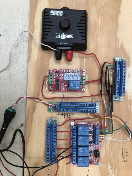
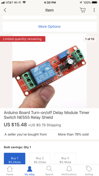
As you await the multifunction cycling relay module, here's some additional background.  You can google FRM01 which is the model number and get dozens of youtube videos on how to use it.  There are instructions but the original translation was virtually incomprehensible translation and DIY'ers have taken it upon themselves to re-write it.  Attached is what I think is a pretty good version.

You want to set the module to Function Mode 06 with parameters as shown.  This will make more sense once you have the module in-hand and review the Instructions.

frm01 mode6 for dcsrc cycling

The FRM01 will apply track power to the (unmodified) DCSRC for 1.0 seconds, the watchdog will be generated, then power is removed for 0.1 seconds, then cycles forever.  

frm01 mode6 connection to dcsrc

Here it is in action.  You can hear the relay clicking on and off.  You can see the green LED on the DCSRC turn ON for 1.0 seconds, then briefly turn OFF for 0.1 seconds.

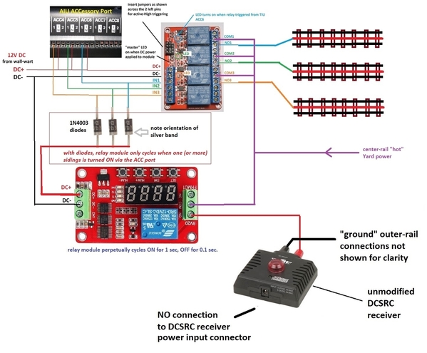
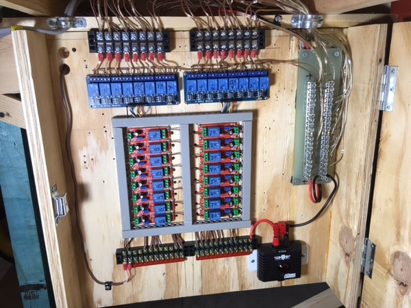
The relay cycles ON-OFF, and the DCSRC cycles ON-OFF as longs as 12V DC power is applied....even if NO sidings are active.  The wiring configuration might be something like:

AIU siding power with stock DCSRC a FRM01

Perhaps you can't see/hear the cycling module in a noisy train room but it was driving me nuts just in the few minutes I was taking the video!  So for 1 penny per siding, here's a suggested modification that turns on the cycling ONLY if one (or more) sidings is actually powered on by an AIU ACC port.

AIU siding power with stock DCSRC a FRM01 and diodes

The added diodes (one per siding installed as shown) turn on the FRM01 module only if a siding is active!  This has the benefit of reducing wear-and-tear on the electro-mechanical relay contacts cycling thousands of times per hour.  I suggest the common 1N4003 diode which is a useful component to have around for a variety of O-gauge DIY projects - very inexpensive.

1n4003 diodes for a penny a piece


Attachments

Stan! This is great. I picked up two of the DCSRCs for $25 and I’m waiting for the circuit board.  I’ve been looking for wiring distribution connectors so that I can straighten out the mess of spaghetti that I created while getting the original relays working. Any suggestions? What amperage load do I need to address?


The switched track-voltage wires on the right side of the diagram (connected to the relays) carry whatever current your yard siding(s) carry.  So maybe 5 Amps max - note that you trains should not be zooming around in a yard.  The control signal wiring from the AIU to the relay modules carry 10 to 100 times less current.  I figure you're using, say, AWG 14/16 wiring for mainline track.  The control signals can be AWG 24/26.  Practically speaking you're probably buying the heavy wiring in spools so just use that.  And you can get good deals on spool of multi-conductor 24/26 wiring used for alarms, sprinklers, telecom, whatever. 

There is nothing particularly tricky about this wiring that would make the distribution method best suited to a specific connector type or scheme. 


Stan,

You’re right, no one will be rushing around the yard. Just for my own practice, I am controlling two loops and one siding with the AIU.  I have an older MTH Premuer Baldwin shark that someone converted to PS2 to PS3 for me. I’ve been running it in the larger loop and after a while (5-10 minutes), the circuit breaker in my ZW goes off and shuts down everything. Even with jusg that loop powered up. I have a 15 circuit breaker betwen the ZW and the tracks, it does not go off.  I’m thinking that I have a bit of a short inside the shark.

But, the reason I asked about track amperage is that I found some connector blocks that appeal to me. They have an amperage rating of 6 amps. (See the photo) I’m thinking that they should be fine fir the distribution of power.

Thanks,

George

Attachments

Images (1)
  • 9B526959-42EC-4575-B3A9-5A96EF7ACF6C

Stan,

You’re right, no one will be rushing around the yard. Just for my own practice, I am controlling two loops and one siding with the AIU.  I have an older MTH Premuer Baldwin shark that someone converted to PS2 to PS3 for me. I’ve been running it in the larger loop and after a while (5-10 minutes), the circuit breaker in my ZW goes off and shuts down everything. Even with jusg that loop powered up. I have a 15 circuit breaker betwen the ZW and the tracks, it does not go off.  I’m thinking that I have a bit of a short inside the shark.

But, the reason I asked about track amperage is that I found some connector blocks that appeal to me. They have an amperage rating of 6 amps. (See the photo) I’m thinking that they should be fine fir the distribution of power.

Thanks,

George

Attachments

Images (1)
  • A2ED9FE0-E4DB-4842-AF31-8337DA433893

Here’s a photo of the layout:

61809B92-0B26-4076-A56C-7EDF3A1602E0

Each track is powered on through the AIU. The siding, with the two engines, is receiving a wake up signal from the little  MTH controller. Success! Neither engine starts until I issue the startup command in the remote. 

B2A0C40A-F0CF-4CC6-924B-103DDEDD0E93

I know that the wiring looks bad but it’s a 100% improvement over the original rates nest. Can I use the same DCSRC to issue wake up signals for the other two tracks?

Thank you for all the help!

Attachments

Images (2)
  • 61809B92-0B26-4076-A56C-7EDF3A1602E0
  • B2A0C40A-F0CF-4CC6-924B-103DDEDD0E93
George Mason posted:
 

... Can I use the same DCSRC to issue wake up signals for the other two tracks?

Not sure I understand the question.  In your photo it appears everything (both loops and the siding) are powered by the TIU Fixed-1 output.  The DCSRC provides the watchdog signal to silence any engines on the siding when the siding is turned on.

Since the two loops are always directly connected/powered to the Fixed-1 output, they will have received the watchdog when the TIU Fixed-1 was initially turned on.  What am I missing? 

AIU%2520siding%2520power%2520with%2520stock%2520DCSRC%2520a%2520FRM01

I think I get it.  Above diagram reflects your "test" layout.  Inner loop, outer loop, and siding are each independently powered by an AIU ACC output.

So this is kind of like a 3-siding configuration...except 2 of the sidings are just your inner and outer loops.

I take it your DCSRC is "merrily" clicking away about once per second?

Attachments

Images (1)
  • AIU%2520siding%2520power%2520with%2520stock%2520DCSRC%2520a%2520FRM01

It could be. I haven’t listened to it carefully. The only reason that I set up the two loops as sidings was to learn the ins and outs of the relays and the little control box. It’s really slick! Makes me feel like I am in control of (some) things!

One more question....what gauge wire do you all use 14 or 16? Stranded or solid? And what’s your feelings about using the power bricks?

Could not have done it without your and John’s help. Now I can start planning the real thing!

Thanks again!

George

George Mason posted:

...

One more question....what gauge wire do you all use 14 or 16? Stranded or solid? And what’s your feelings about using the power bricks?

That's 3 questions!  

You're better off asking these questions in a separate thread in that the issues of configuring the AIU, relays, DCSRC, etc. for the application of silencing DCS engines on power-up are essentially independent of the type of wiring and power source.

stan2004 posted:

AIU%2520siding%2520power%2520with%2520stock%2520DCSRC%2520a%2520FRM01

I think I get it.  Above diagram reflects your "test" layout.  Inner loop, outer loop, and siding are each independently powered by an AIU ACC output.

So this is kind of like a 3-siding configuration...except 2 of the sidings are just your inner and outer loops.

I take it your DCSRC is "merrily" clicking away about once per second?

Stan, I noticed that you indicate the power coming from the "Fixed 1 output".  Early on, for some reason, I opted for the variable output.  I am having some difficulty wiring the relays and the DCSRC in the manner that you show in the above diagram. No matter what I do, the engine on the siding powers up in conventional mode when I turn on the power for the siding. I am also not sure how to program the intermittent relay. Any help is appreciated.

stan2004 posted:

AIU%2520siding%2520power%2520with%2520stock%2520DCSRC%2520a%2520FRM01

I think I get it.  Above diagram reflects your "test" layout.  Inner loop, outer loop, and siding are each independently powered by an AIU ACC output.

So this is kind of like a 3-siding configuration...except 2 of the sidings are just your inner and outer loops.

I take it your DCSRC is "merrily" clicking away about once per second?

The DCSEC does not appear to be doing anything, Should either of the DCSRC lights be on?  I checked the wiring again and again.  I may not have the intermittent relay programmed correctly. 

Should be no problem using a VAR channel instead of a FIXED. But, if given a choice, I'd just use FIXED 1.  Especially in what I believe is your end configuration of just ONE DCS channel powering your 2 loops and 1 siding.

Anyway, are you saying you can't get the FRM01 timer module to cycle on and off as shown in the video?  This is a matter of programming the FRM01 (which I acknowledge can be tricky) using the PDF instructions I attached in a previous post.  You don't even need the DCSRC attached to see if the FRM01 is "working".  When programmed correctly to Function 6 it will merrily click (and on-board LED flashes) - 1 second on, 0.1 seconds off.  

frm01 paramter setting


Attachments

Images (1)
  • frm01 paramter setting
stan2004 posted:

Should be no problem using a VAR channel instead of a FIXED. But, if given a choice, I'd just use FIXED 1.  Especially in what I believe is your end configuration of just ONE DCS channel powering your 2 loops and 1 siding.

Anyway, are you saying you can't get the FRM01 timer module to cycle on and off as shown in the video?  This is a matter of programming the FRM01 (which I acknowledge can be tricky) using the PDF instructions I attached in a previous post.  You don't even need the DCSRC attached to see if the FRM01 is "working".  When programmed correctly to Function 6 it will merrily click (and on-board LED flashes) - 1 second on, 0.1 seconds off.  

frm01 paramter setting


Yes it’s clicking merrily! And I programmed F6 as you specified. However the engine on the isolated track starts up in conventional mode. The DCSRC keeps on clicking after the power to the track is disconnected.

George Mason posted:
stan2004 posted:

Should be no problem using a VAR channel instead of a FIXED. But, if given a choice, I'd just use FIXED 1.  Especially in what I believe is your end configuration of just ONE DCS channel powering your 2 loops and 1 siding.

Anyway, are you saying you can't get the FRM01 timer module to cycle on and off as shown in the video?  This is a matter of programming the FRM01 (which I acknowledge can be tricky) using the PDF instructions I attached in a previous post.  You don't even need the DCSRC attached to see if the FRM01 is "working".  When programmed correctly to Function 6 it will merrily click (and on-board LED flashes) - 1 second on, 0.1 seconds off.  

frm01 paramter setting


Yes it’s clicking merrily! And I programmed F6 as you specified. However the engine on the isolated track starts up in conventional mode. The DCSRC keeps on clicking after the power to the track is disconnected.

I had the wires on the track relay reversed all is well. Now, how do I stop that annoying clicking?

There are (at least) 4 alternatives to the annoying perpetual clicking.

1. Earplugs.

2. The original modified DCSRC, a.k.a. Perpetual Barking Watchdog.  No moving parts (no relay) so no clicking.

3. Use one Delay-OFF relay module for each loop or siding that's under relay control.  The Delay-OFF module will turn on (one click) the DCSRC for 1 second when power is first applied to the loop or siding.  The DCSRC generates the watchdog to silence the engine(s) on that newly powered section.  Then 1 second later the DCSRC turns off (a 2nd click) and stays off and silent no matter how long that section remains powered.  A diagram of this was shown in the post of 5/7.

4. Use one diode per loop or siding to only power the FRM01 when one (or more) loop or siding is actually powered.  So if no loop or siding is powered, the FRM01 is off and silent.   A diagram of this was shown in the post of 5/11.   But to be clear, you'll hear the clicking sound as long as one (or more) loops or sidings are active.

I think you said you bought a couple FRM01 modules?  If so you can experiment with method 3 by programming your FRM01 module to be a Delay-OFF module.  In other words, when triggered it will turn its relay ON (and power the DCSRC) for exactly 1 second and then turn off.  Obviously for many sidings this gets expensive since the FRM01 relay module is 2-3 times the cost of a simple Delay-OFF relay.

Last edited by stan2004
stan2004 posted:

There are (at least) 4 alternatives to the annoying perpetual clicking.

1. Earplugs.

2. The original modified DCSRC, a.k.a. Perpetual Barking Watchdog.  No moving parts (no relay) so no clicking.

3. Use one Delay-OFF relay module for each loop or siding that's under relay control.  The Delay-OFF module will turn on (one click) the DCSRC for 1 second when power is first applied to the loop or siding.  The DCSRC generates the watchdog to silence the engine(s) on that newly powered section.  Then 1 second later the DCSRC turns off (a 2nd click) and stays off and silent no matter how long that section remains powered.  A diagram of this was shown in the post of 5/7.

4. Use one diode per loop or siding to only power the FRM01 when one (or more) loop or siding is actually powered.  So if no loop or siding is powered, the FRM01 is off and silent.   A diagram of this was shown in the post of 5/11.   But to be clear, you'll hear the clicking sound as long as one (or more) loops or sidings are active.

I think you said you bought a couple FRM01 modules?  If so you can experiment with method 3 by programming your FRM01 module to be a Delay-OFF module.  In other words, when triggered it will turn its relay ON (and power the DCSRC) for exactly 1 second and then turn off.  Obviously for many sidings this gets expensive since the FRM01 relay module is 2-3 times the cost of a simple Delay-OFF relay.

I went back and reviewed the information that you posted earlier. And, as luck would have it, the local mom and pop electronics store had the diodes! 

Could not get the diode to work. So, I found the FRM01 User Manual on line and opted for function two - ON when power applied for XXXX seconds and OFF when zero is reached. Power OFF the siding and power it ON and all is right with the world!

I installed, operated, and managed computer systems for 36 years but never delved very deeply into the electronic level for much other than configuring an I/O board or device with DIP switches.  This is a different level of programming but the same principles as programming in Fortran.

I know that the module costs more but it provides a lot of flexibility.

Thanks for the help!

I'm sure we could work out the diode method, but if you have something that works for you then life is good! 

The FRM01, at less than $5 shipped, is an incredibly versatile timer-relay module with many applications in O-gauge.  Once you settle on a method to silence engines on newly powered siding/loop, you can then choose to save a few bucks with a single-purpose timer-relay module rather than the multi-purpose FRM01 module.


stan2004 posted:
gunrunnerjohn posted:

Sounds like George really needs a couple of the A&T Perpetual Barking Watchdog boards to equip a couple of DCSRC units.

Agreed.  BUT I believe procuring a resistor here, a capacitor there, messing with bare circuit-boards, soldering, testing, etc. can be a hurdle for a lot of guys.

Soooo...here's my latest hare-brained scheme.  This uses $2 (free shipping from Asia) eBay "Delay-OFF" relay modules.  You need one Delay-OFF relay module per siding.  But one unmodified (stock) DCSRC receiver can serve multiple sidings.

12v delay OFF relay module 2 bucks on eBay

AIU siding power with stock DCSRC

Here's the idea.  A Delay-OFF relay module turns on for some fixed settable period, then it turns OFF.  So when power is applied to a particular siding using the existing external relay module, a paired Delay-OFF relay also turns on for, say, 5 seconds.  The Delay-OFF relay module momentarily (for 5 seconds or whatever) attaches the DCSRC to the newly powered siding.  The DCSRC generates its "watchdog" signal to the newly powered siding.  The Delay-OFF relay module then turns off (after 5 seconds)...but track power is still applied to the siding since the main power relay is still ON as controlled by the ACC port.

So after 5 seconds, the DCSRC is disconnected and turned OFF.  This means the DCSRC is ready to be paired to an additional siding that gets powered ON.  Thus, one DCSRC can service multiple sidings...AND multiple sidings can be active!

I realize this is all getting somewhat convoluted but this is a discussion forum to share ideas. 


I reworked the siding actuator per your previous diagram. It works perfectly! Thank you!


I would like to reduce the size but I not sure where to start. The biggest space wasters are the terminal blocks. Do you ever wonder why no one sells these?

Attachments

Images (1)
  • mceclip0
milwrd posted:

George, you sure have a point in regard to the terminal blocks hogging up the space. I wish I had seen the ones you used as they are definitely than the version I used. On the plus side, there a lot easier to work with.


I found those on eBay but I don’t remember whose they are. What type of wire are you using? I used 18 gauge thermostat wire which is a bit hard to work with.

milwrd posted:

That is the setup for the roundhouse and whiskers around my turntable. I initially was powering my turntable with two on the relays but didn't like how it was working. Back to the drawing board for that solution.  

I just noticed something about the FRM01 relay board that I’m using to power up my two sidings. When I activate the first siding, the DCS signal generator lights and the siding powers up with the engine silent. The FRM01 displays 02 (function) and it does it power off. When I activate the second siding, the FRM01 program does not run and the signal generator does not fire. Any ideas about what I did wrong?

Since the FRM01 has screw-terminals, swap the two FRM01 modules and see if the problem follows the FRM01 or stays with the siding.

If that doesn't reveal anything, let us know exactly what your current configuration is.  I was reviewing earlier posts in this thread and there have been so many variations that I'm lost as to exactly which setup you now have!    A photo might be useful.   

stan2004 posted:

Since the FRM01 has screw-terminals, swap the two FRM01 modules and see if the problem follows the FRM01 or stays with the siding.

If that doesn't reveal anything, let us know exactly what your current configuration is.  I was reviewing earlier posts in this thread and there have been so many variations that I'm lost as to exactly which setup you now have!    A photo might be useful.   

Here’s how it looks now:

There are two sidings. When I start one, the engine on that track remains dormant. When I start the second siding, the engine powers up. If I shut them off and reverse the startup order, the second one powers up. So, I don’t think that moving the wires would make a difference.

Attachments

Images (1)
  • mceclip0

OK, I misunderstood.  I thought you had 2 FRM01's (one per siding).  To be clear, are those diodes shown in the yellow boxes under the black heat shrink?  And they are oriented with the white or silver stripe/band on the bottom side as illustrated?

mceclip0

I believe the FRM01 has a power-on LED that lights whenever power is applied...and a different relay-on LED that turns on when the relay clicks on.  I assume that once you turn on the first siding (whether it be siding A or siding B), the FRM01 power-on LED turns on and stays on even after the relay clicks on then off.  Right?  

In other words, the FRM01 is performing the Delay-OFF function once and only once for the first siding.  Then the FRM01 is now on and does not "re-trigger" its Delay-OFF function for the second (third, fourth, etc.) siding.  This is the classic re-trigger conundrum.  As shown in this earlier diagram, if using the FRM01 "Function 02", there is one timer module PER SIDING.  So in your 2 siding test setup, that would be 2 FRM01's set to Function 02.

AIU%2520siding%2520power%2520with%2520stock%2520DCSRC

Separately, do you have a "stash" of assorted capacitors lying around?  Just thinking ahead for possible work-arounds...


Attachments

Images (2)
  • mceclip0
  • AIU%2520siding%2520power%2520with%2520stock%2520DCSRC
stan2004 posted:

OK, I misunderstood.  I thought you had 2 FRM01's (one per siding).  To be clear, are those diodes shown in the yellow boxes under the black heat shrink?  And they are oriented with the white or silver stripe/band on the bottom side as illustrated?

mceclip0

I believe the FRM01 has a power-on LED that lights whenever power is applied...and a different relay-on LED that turns on when the relay clicks on.  I assume that once you turn on the first siding (whether it be siding A or siding B), the FRM01 power-on LED turns on and stays on even after the relay clicks on then off.  Right?  

In other words, the FRM01 is performing the Delay-OFF function once and only once for the first siding.  Then the FRM01 is now on and does not "re-trigger" its Delay-OFF function for the second (third, fourth, etc.) siding.  This is the classic re-trigger conundrum.  As shown in this earlier diagram, if using the FRM01 "Function 02", there is one timer module PER SIDING.  So in your 2 siding test setup, that would be 2 FRM01's set to Function 02.

AIU%2520siding%2520power%2520with%2520stock%2520DCSRC

Separately, do you have a "stash" of assorted capacitors lying around?  Just thinking ahead for possible work-arounds...


No, just one FRM01. The original schematic showed just one. And yes, the “relay on” LED remains lit after the first use. 

I’m fairly certain that the diodes are pointed in the correct direction. I can meter them to verify that.

I guessed that I had to have one per siding, so I ordered these....

I am hoping that this is what I need. I was also hoping that there is a function in the FRM01 that would turn off the FRM01 once the program finished running. In other words, I hoped that one FRM01 could service multiple sidings.

No stash of capacitors, but I can always get some.

Attachments

Images (1)
  • mceclip0
George Mason posted:
 
I guessed that I had to have one per siding, so I ordered these....

I am hoping that this is what I need. I was also hoping that there is a function in the FRM01 that would turn off the FRM01 once the program finished running. In other words, I hoped that one FRM01 could service multiple sidings.

No stash of capacitors, but I can always get some.

But aren't those the same relays as you proposed in this earlier post?

https://ogrforum.ogaugerr.com/...66#79142442769473066

In my response to that post I warn that they are NOT "Delay OFF" modules despite whatever the item description says.  They are "Delay ON" modules which is not what you want.    Again you want a Delay OFF module which works as follows.  1) You apply 12V power to the module, 2) Relay immediately turns on, 3) after some settable delay such as 5 seconds, the relay turns off and stays off even though 12V power is still applied.  To trigger the relay again, remove 12V power and go to step 1).   The FRM01 programmed to Function 02 is behaving as a Delay OFF module.  As you confirmed, after it performs its delay-OFF once, you cannot re-trigger it unless you remove 12V power and start again.

I show an example of a true Delay-OFF module in my recent posts.  They are less than $2 on eBay (free shipping from Asia).  I'm sure they are also on Amazon too with a suitable markup if being shipped from within US.   Or, you can use 1 FRM01 per siding.

-----

One might argue that 10 x $2 = $20 for a pile of Delay-OFF modules would let you be done with it and move on, albeit with some assembly/wiring handiwork.  I asked about capacitors because the FRM01 Function 02 has an interesting feature which allows you to re-trigger the delay on that 3rd "unused" screw-terminal input.  I'd have to mess with it, but there may be a way to use 1 capacitor per siding to re-trigger the FRM01 Function 02 whenever a new siding is turned on even if one or more sidings have already been turned on.  

stan2004 posted:
George Mason posted:
 
I guessed that I had to have one per siding, so I ordered these....

I am hoping that this is what I need. I was also hoping that there is a function in the FRM01 that would turn off the FRM01 once the program finished running. In other words, I hoped that one FRM01 could service multiple sidings.

No stash of capacitors, but I can always get some.

But aren't those the same relays as you proposed in this earlier post?

https://ogrforum.ogaugerr.com/...66#79142442769473066

In my response to that post I warn that they are NOT "Delay OFF" modules despite whatever the item description says.  They are "Delay ON" modules which is not what you want.    Again you want a Delay OFF module which works as follows.  1) You apply 12V power to the module, 2) Relay immediately turns on, 3) after some settable delay such as 5 seconds, the relay turns off and stays off even though 12V power is still applied.  To trigger the relay again, remove 12V power and go to step 1).   The FRM01 programmed to Function 02 is behaving as a Delay OFF module.  As you confirmed, after it performs its delay-OFF once, you cannot re-trigger it unless you remove 12V power and start again.

I show an example of a true Delay-OFF module in my recent posts.  They are less than $2 on eBay (free shipping from Asia).  I'm sure they are also on Amazon too with a suitable markup if being shipped from within US.   Or, you can use 1 FRM01 per siding.

-----

One might argue that 10 x $2 = $20 for a pile of Delay-OFF modules would let you be done with it and move on, albeit with some assembly/wiring handiwork.  I asked about capacitors because the FRM01 Function 02 has an interesting feature which allows you to re-trigger the delay on that 3rd "unused" screw-terminal input.  I'd have to mess with it, but there may be a way to use 1 capacitor per siding to re-trigger the FRM01 Function 02 whenever a new siding is turned on even if one or more sidings have already been turned on.  

Thanks Stan. I was misled by the description. I’ll order the other modules. Can you tell that I don’t know much about electronic components?

Stan, I think that I may be on to something. I learned that applying  DC+  to CH1 on the FRM01, it forces the FRM01 to rerun the program. The wires from the accessory ports of the AIU go to IN1 to 4 on the track power relay board. If I run a wire from each of those to the CH1 port on the FRM01, won’t that force the wake up signal to go to the intended track?

Correct.  The Function 02 mode permits re-triggering the DELAY-OFF function by applying a momentary trigger pulse to the CH1 port.  The key is it must be a momentary pulse.  So to review, here's what you have right now:

mason 4-8-2019 function 02 delay OFF no re-trigger

Turning on one or more ACC ports triggers the FRM01 to generate one DELAY-OFF cycle to the DCSRC.  Once an ACC port is turned on, the FRM01 has already done its deed and is sitting with power applied but idle.  Turning on additional ACC ports has no effect.  This is as expected.

mason 4-8-2019 function 02 delay OFF using re-trigger

But as you discovered, Function 02 support re-triggering using the CH1 port.  This is shown in the revised diagram above.  If you simply run the common wire after the diodes into the CH1 trigger port, you will get a trigger for the first siding turned on.  But now the signal is "ON" as long as that siding is powered.  Turning on additional ACC ports has no effect since CH1 is already "ON".  Hence, in earlier posts I asked about your stash of capacitors.  One could devise what should be an inexpensive circuit (likely involving capacitors) that would generate a momentary pulse to trigger the CH1 port whenever an ACC port turns on, even if another ACC port is already on.

This is shown in the crude timing diagram.  It shows ACC1 turning on which generates a trigger.  Then ACC2 turns on which generates another trigger (even though ACC1 already on).  ACC1 turns off but no trigger.  ACC1 turns on again and generates a trigger (even through ACC2 already ON).  Etc.

It's not that the capacitor circuit would be expensive - maybe $1-$2 out-of-pocket to allow 5 or 10 sidings to share a single FRM01.  It's just that now you have "loose" components ( capacitors, resistors, whatever) hanging about.  Hence using $2 Delay-OFF modules, albeit one per siding, seemed more straightforward.

But I suppose a determined DIY'er who knows which end of a soldering iron to hold could argue it would be a more compact solution, save a few bucks, and maybe have some fun fiddling with electronics along the way.  I suspect in the cost saving category, there is undoubtedly a triggerable DELAY-OFF module that is less expensive than the FRM01.  If this is something you'd like to pursue I can poke around an FRM01 to see what kind of CH1-trigger signal it needs and probably concoct an inexpensive and easy-to-assemble circuit to use the Function 02 re-trigger capability.

Attachments

Images (2)
  • mason 4-8-2019 function 02 delay OFF no re-trigger
  • mason 4-8-2019 function 02 delay OFF using re-trigger
Last edited by stan2004
stan2004 posted:

I hear you.  Changing horses mid-stream can be fraught with peril. 

At less than $5 shipped, the FRM01 is a gift that keeps on giving!  I continually find new O-gauge applications for it.

frm01 for less than 5 bucks 


Stan, I cannot seen to be able to find the right relays. I have some NE555 relays that can power off a device or power it on, depending how I connect the wires to the board.  I cant seem to be able to get them correctly wired into the siding system. I’ve torn it apart and am starting over again from scratch.

If we're talking about the one relay module PER siding method, this requires a DELAY-OFF module.  As mentioned previously, some of the relay modules online are not-as-described.  

Delay-then-OFF relay modules

Above show some modules that will work.  The more expensive multi-function timers can perform more tricks.  The two on top require a one-time "programming" to select the mode to Delay-off and to set the timing parameters.  The one on the bottom "only" performs the delay-off function and you simply turn the adjustment control to set the delay time; one of my earlier posts shows an ebay listing and I'd think the item description would be the same if you prefer Amazon or similar US distributor.

As I understand it, you may have some delay modules (that use the NE555 IC chip) but they are NOT of the Delay-OFF type.  As is often the case, there are ways to hack them to change functionality but really not worth the effort when you can get exactly what you want for just a couple bucks.

Attachments

Images (1)
  • Delay-then-OFF relay modules

Here is the simplified illustration that Stan was kind enough to supply us and the basis for the panel I put together in the picture I posted above. Only thing different for me was the second batch of latching relays I received from our Asian friends used a negative trigger instead so I had to flip the diodes and switch the lead from the FRM01 and use the negative side. Thanks again Stan. 

Attachments

Images (1)
  • mceclip0
stan2004 posted:

If we're talking about the one relay module PER siding method, this requires a DELAY-OFF module.  As mentioned previously, some of the relay modules online are not-as-described.  

Delay-then-OFF relay modules

Above show some modules that will work.  The more expensive multi-function timers can perform more tricks.  The two on top require a one-time "programming" to select the mode to Delay-off and to set the timing parameters.  The one on the bottom "only" performs the delay-off function and you simply turn the adjustment control to set the delay time; one of my earlier posts shows an ebay listing and I'd think the item description would be the same if you prefer Amazon or similar US distributor.

As I understand it, you may have some delay modules (that use the NE555 IC chip) but they are NOT of the Delay-OFF type.  As is often the case, there are ways to hack them to change functionality but really not worth the effort when you can get exactly what you want for just a couple bucks.

The top one is the FRM01 that I started all this with. I was able to get one of the NE555 boards to turn on power to the siding and simultaneously activate the DSC signal. But, it created other problems that I haven’t tracked down. The bottom line is that the NE555 board remains powered on until I turn off the siding. Which isn’t a bad thing.

George Mason posted:
 

The top one is the FRM01 that I started all this with. I was able to get one of the NE555 boards to turn on power to the siding and simultaneously activate the DSC signal. But, it created other problems that I haven’t tracked down. The bottom line is that the NE555 board remains powered on until I turn off the siding. Which isn’t a bad thing.

When you say "remains powered on" do you mean the RELAY on the board remains powered on?  When a new siding turns on, the RELAY on the NE555 board should only turn on for a few seconds and then click off and remain off even if the NE555 board itself remains powered on.  This is critical to the operation of this method.  The DCSRC must turn on for only a few seconds when any new siding is powered up.  The DCSRC must then turn off until another siding is powered on.  This is because the DCSRC only generates the magic watchdog signal when it initially received power.

And of course the above only applies to the current method under discussion which uses a "stock" unmodified DCSRC.  If using the modified DCSRC (a.k.a. Perpetual Barking Watchdog) or a FRM01-like timer programmed to continuously cycle power on and off to a stock DCSRC, you do not need to mess with the Delay-OFF timer relay modules.

milwrd posted:

...

Only thing different for me was the second batch of latching relays I received from our Asian friends used a negative trigger instead so I had to flip the diodes and switch the lead from the FRM01 and use the negative side. 

6 LATCH

So there is a version of the 6-latching-relay module that looks like the above but does NOT come with the jumper-plug that allows you to select high vs. low trigger?   I suppose only offering one polarity of triggering could save a tad (a small tad) in component costs.

Attachments

Images (1)
  • 6 LATCH

The first and second batch of relays look identical, jumper selection and all, save the led that shows there powered up (green vs red). However, when I wired up the second batch (all the jumpers in the same location) they wouldn't work with 12+. I thought I had some bad boards until I tried 12- and they worked, go figure.

milwrd posted:

Here is the simplified illustration that Stan was kind enough to supply us and the basis for the panel I put together in the picture I posted above. Only thing different for me was the second batch of latching relays I received from our Asian friends used a negative trigger instead so I had to flip the diodes and switch the lead from the FRM01 and use the negative side. Thanks again Stan. 

Sir, I have mine wired as above. I am using program 02 on the FRM01. When turning on the first siding, it goes through it’s program and remains on. Powering on the second siding does not cause it to rerun the program. The only thing that will do that is the application of DC+ to post CH1 on the FRM01. I cannot determine what I have done wrong.

George, note that as detailed in this earlier post:

https://ogrforum.ogaugerr.com/...51#79142442810812251

the FRM01 was set to the perpetual cycling mode (Function 06):

mceclip0

As long as one or more sidings is active, the FRM01 will be clicking on-off-on-off-etc. about once per second.  It was this perpetual mechanical clicking that I thought was annoying and hence suggested the one timer relay module per siding...so you'd only get a single click when a new siding was powered.

So if your setup is wired exactly as shown above (with the diodes installed), you should be able to set the FRM01 to Function 06 with T1=1.0 sec on, T2=0.1 sec off and your 2 siding test set up should work.  But to be clear, whenever one or both sidings are on, the FRM01 will be clicking.  If neither siding is powered, the FRM01 is dark and silent.

Attachments

Images (1)
  • mceclip0
stan2004 posted:

George, note that as detailed in this earlier post:

https://ogrforum.ogaugerr.com/...51#79142442810812251

the FRM01 was set to the perpetual cycling mode (Function 06):

mceclip0

As long as one or more sidings is active, the FRM01 will be clicking on-off-on-off-etc. about once per second.  It was this perpetual mechanical clicking that I thought was annoying and hence suggested the one timer relay module per siding...so you'd only get a single click when a new siding was powered.

So if your setup is wired exactly as shown above (with the diodes installed), you should be able to set the FRM01 to Function 06 with T1=1.0 sec on, T2=0.1 sec off and your 2 siding test set up should work.  But to be clear, whenever one or both sidings are on, the FRM01 will be clicking.  If neither siding is powered, the FRM01 is dark and silent.

Yep! It’s annoying. It’s a shame that I can’t take advantage of the CH1 to get it to recycle on program 02. Thanks.

Curiosity got the better of me so I extracted the CH1 trigger input circuit of the FRM01.  Here's one way to take advantage of CH1 and the FRM01 Function 02 so that a single FRM01 can handle multiple sidings using an unmodified (stock) DCS Remote Commander to supply the watchdog signal.

mason trigger

Following each 1N4003 diode, insert 3 cents of parts (a 1M resistor and a 1uF capacitor) as shown.  To be clear, I do not recommend this since it means messing with loose components and soldering.  

rc%2520trigger%2520parts%2520to%2520frm01%2520ch1

I present this for the record as I can imagine other AIU applications where multiple ACC(essory) ports can trigger a single FRM01 to perform some kind of timing/delay function for layout accessories.

Attachments

Images (2)
  • mason trigger
  • rc%2520trigger%2520parts%2520to%2520frm01%2520ch1
Last edited by stan2004
stan2004 posted:

Curiosity got the better of me so I extracted the CH1 trigger input circuit of the FRM01.  Here's one way to take advantage of CH1 and the FRM01 Function 02 so that a single FRM01 can handle multiple sidings using an unmodified (stock) DCS Remote Commander to supply the watchdog signal.

mason trigger

Following each 1N4003 diode, insert 3 cents of parts (a 1M resistor and a 1uF capacitor) as shown.  To be clear, I do not recommend this since it means messing with loose components and soldering.  

rc%2520trigger%2520parts%2520to%2520frm01%2520ch1

I present this for the record as I can imagine other AIU applications where multiple ACC(essory) ports can trigger a single FRM01 to perform some kind of timing/delay function for layout accessories.

Right now, I have it working. The constant clicking gets a bit old, but at least it’s functioning. I may try another set up with this design and see how I like it. What do you recommend as a board to build these on? Is there a perforated soldering medium to build it on?

I'd say the most popular "perforated soldering medium" is the prototype PCB.  They are pre-drilled with solder rings on a 0.1" (2.54mm) grid.  Pretty much all are 1/16" (1.6mm) thick and cuttable with a hobby/hack saw.  There are even screw-terminal connectors that fit this grid - 0.1" (2.54mm) shown in photo in 2-pole and 3-pole.  Though I must say 0.1" screw-terminal blocks are quite tiny to work with in which case there are 0.2" screw-terminal blocks that drop in skipping a hole.  On eBay use 2.54mm or 5.08mm in search.

prototype pcb 100mil grid

Wire terminals on resistors and capacitors are a couple inches on each side.  So since this is such a "simple" circuit you can probably use the wire terminals themselves to make all the interconnections in a point-to-point fashion.  In other words, you shouldn't have to cut and strip short lengths of insulated wiring to make the interconnections on the "bottom" of the board.

Attachments

Images (1)
  • prototype pcb 100mil grid
stan2004 posted:

I'd say the most popular "perforated soldering medium" is the prototype PCB.  They are pre-drilled with solder rings on a 0.1" (2.54mm) grid.  Pretty much all are 1/16" (1.6mm) thick and cuttable with a hobby/hack saw.  There are even screw-terminal connectors that fit this grid - 0.1" (2.54mm) shown in photo in 2-pole and 3-pole.  Though I must say 0.1" screw-terminal blocks are quite tiny to work with in which case there are 0.2" screw-terminal blocks that drop in skipping a hole.  On eBay use 2.54mm or 5.08mm in search.

prototype pcb 100mil grid

Wire terminals on resistors and capacitors are a couple inches on each side.  So since this is such a "simple" circuit you can probably use the wire terminals themselves to make all the interconnections in a point-to-point fashion.  In other words, you shouldn't have to cut and strip short lengths of insulated wiring to make the interconnections on the "bottom" of the board.

How does this look as a parts list?

https://ogrforum.ogaugerr.com/.../Shopping%20cart.pdf

Attachments

I don't see the capacitors in your basket?  If you prefer USA sellers, how about the following.  In most cases I found you more parts for less $.  I'm not sure the size of the Prototyping board you chose, but the one shown below is more than large enough and much less $.  So to be clear, you're undertaking this DIY for fun-and-amusement as part of the hobby?  I thought we had settled on a one-per-siding Delay-Off relay module approach (no soldering) and that you had already ordered modules. 

mason usa ebay parts

Attachments

Images (1)
  • mason usa ebay parts
Last edited by stan2004
stan2004 posted:

I don't see the capacitors in your basket?  If you prefer USA sellers, how about the following.  In most cases I found you more parts for less $.  I'm not sure the size of the Prototyping board you chose, but the one shown below is more than large enough and much less $.  So to be clear, you're undertaking this DIY for fun-and-amusement as part of the hobby?  I thought we had settled on a one-per-siding Delay-Off relay module approach (no soldering) and that you had already ordered modules. 

mason usa ebay parts

Did not order them yet. I tried to find suppliers that could get the parts to me in a reasonable amount of time. I’ll use your list of parts. I chose a larger board so that I could mount the FRM01 and the power relay board all together. I’m not planning on using the delay-off relays. I am going to follow this diagram.

And yes I’m doing this my enjoyment. And hopefully implement this when I start building a more permanent layout.

Attachments

Images (1)
  • mceclip0
stan2004 posted:

Curiosity got the better of me so I extracted the CH1 trigger input circuit of the FRM01.  Here's one way to take advantage of CH1 and the FRM01 Function 02 so that a single FRM01 can handle multiple sidings using an unmodified (stock) DCS Remote Commander to supply the watchdog signal.

mason trigger

Following each 1N4003 diode, insert 3 cents of parts (a 1M resistor and a 1uF capacitor) as shown.  To be clear, I do not recommend this since it means messing with loose components and soldering.  

rc%2520trigger%2520parts%2520to%2520frm01%2520ch1

I present this for the record as I can imagine other AIU applications where multiple ACC(essory) ports can trigger a single FRM01 to perform some kind of timing/delay function for layout accessories.

Stan, I hope that I’m not bothering you with these questions. I’ve tried applying the circuit using the diode, resistor, and capacitor. It doesn’t seem to want to pass the signal though to the CH1 connection of the FRM01. Am I correct that the resistor and capacitor are non polar? I’ve tried to test continuity from the non-bar end of the diode to the ending lead on the resistor . The meter gave me a reading of one. From the non-bar end of the diode to the first end of the resistor the reading dropped to around 0.5. I have not connected any of this to the AIU for fear of damaging it. Instead, I used a DC 12 v + charge at the diode to simulate the AIU. I’m sure that I have something wrong. Just can’t track it.

It's no bother.  Yes, the resistor and capacitor in the proposed circuit are non-polar in that they can be hooked up either way with equal results...as opposed to the diode which must be hooked up with the bar end as shown.

I'm not sure what your meter is indicating.  Was it set to measure "DCV" (DC Voltage) or something else?

What's tricky about using a meter to measure this circuit is the capacitor.  In basic terms, the "continuity" of the capacitor changes with time when a siding is turned on.  It starts with high continuity and then quickly (in a fraction of a second) drops to low continuity.  The effect of this behavior is to generate a short (fraction of a second) trigger pulse into CH1 which starts the FRM01 timer.  It is virtually impossible to get a usable measure of continuity using a meter since everything happens so quickly!

The introduction of the resistor and capacitor pairs will not damage the AIU.  I think the diagram showing where to add the resistor/capacitor pairs to your existing wiring with the diodes is fairly straightforward.  It does not introduce any "new" sources of power which is where there might be cause for concern.

stan2004 posted:

It's no bother.  Yes, the resistor and capacitor in the proposed circuit are non-polar in that they can be hooked up either way with equal results...as opposed to the diode which must be hooked up with the bar end as shown.

I'm not sure what your meter is indicating.  Was it set to measure "DCV" (DC Voltage) or something else?

What's tricky about using a meter to measure this circuit is the capacitor.  In basic terms, the "continuity" of the capacitor changes with time when a siding is turned on.  It starts with high continuity and then quickly (in a fraction of a second) drops to low continuity.  The effect of this behavior is to generate a short (fraction of a second) trigger pulse into CH1 which starts the FRM01 timer.  It is virtually impossible to get a usable measure of continuity using a meter since everything happens so quickly!

The introduction of the resistor and capacitor pairs will not damage the AIU.  I think the diagram showing where to add the resistor/capacitor pairs to your existing wiring with the diodes is fairly straightforward.  It does not introduce any "new" sources of power which is where there might be cause for concern.

Ok, I set up a small board with a single diode, resistor and capacitor. It’s connected to the FRM01, dc/ac relay board , and the the AIU as diagrammed. When I trigger the AIU, I get 12 VDC through the diode. But when I measures voltage between the diode input and the resistor output, I’m reading 0.33 VDC which isn’t enough to trigger the FRM01.  Did I buy the wrong parts?

Attachments

Images (2)
  • 8B4484A8-B647-401E-9E41-726C12636B42
  • EDDD8496-94F2-4055-A6A5-521FEAA57898

Well, there's good news and bad news

Resistor is correct (if that's brown-black-green-gold stripes).

Capacitor is incorrect.  Photo shows a 1nF (1 nanoFarad) capacitor which is 1000 times small than a 1uF (1 microFarad) capacitor.  Yes, in retrospect I suppose it's a bit confusing to use "u" to abbreviate "micro" - it's a Greek letter thing.   If you're buying this off a rack or whatever at a parts store, the correct label would be as shown.  Even though the correct capacitor value is 1000 times larger, the physical part size will be about the same and should cost about the same.

EDDD8496-94F2-4055-A6A5-521FEAA57898

Attachments

Images (1)
  • EDDD8496-94F2-4055-A6A5-521FEAA57898
Last edited by stan2004

Fast, Cheap, Good. You get to choose 2.  

Untitled

I thought you were just buying at a local store.  Anyway, here's a US seller in your neck of the woods. 19 cents vs. 5 cents each.  If you ordered today I wonder if they'd beat the ones from China! 

My experience with those shipping advisories is I'll get the item about 1 week after "clearing customs" in the US. 


Attachments

Images (1)
  • Untitled

The board is built and (probably did something wrong) it doesn’t function. The first siding turned on, triggers the remote commander. Turning on the second does nothing. In the reverse order, first come first served.

Following, are photos of the board that I put together. Underside is first , top side is last. I ran a wire from the first two inputs on the relay board(sidings 1 snd 2)to the inputs on my concoction. The diode connects to the resistor with the capacitor framing the resistor. The other end of the resistor led to the output connection which is wired to the trigger port of the FR01. First siding powered triggers the FR01 which triggers the MTH remote. Powering on the 2nd siding does nothing.

Any thoughts?

25EF35D5-7A14-4B5A-9BA9-46E579E2A916

822B8367-1E4C-4B52-B240-5D120E71ABB4AEF0979C-0A19-4A1D-88CD-BCCDC566D400AAB3CA51-D243-49DE-8E90-F98D8296EEA1


Attachments

Images (4)
  • 25EF35D5-7A14-4B5A-9BA9-46E579E2A916
  • 400CC3AA-AE4D-4143-BE77-C92C6332A556
  • AEF0979C-0A19-4A1D-88CD-BCCDC566D400
  • AAB3CA51-D243-49DE-8E90-F98D8296EEA1

From what I can see, your wiring looks OK.

So I just wired up 3 "channels".  Each channel (I'll call them A,B,C) is a diode (1N4003) followed by the capacitor (1uF)-resistor (1M) pair going into the FRM01 CH1 trigger terminal.  FRM01 is set to Mode --02 as your photo indicates.  I set the T1 delay to 4 seconds.

I applied 12V to A. FRM01 relay clicks on for 4 seconds.  After relay clicks off, I applied 12V to B (with A still "on") and FRM01 re-triggers for another 4 seconds.  After relay clicks off, I then applied 12V to C (with A and B still "on") and FRM01 re-triggers for another 4 seconds.

I also tried it with the power supply set to 10V DC and 14V DC to rule out any voltage sensitivity in case your 12V supply is not exactly 12V.  Same result.

But I hear what you're saying - you're seeing the circuit fail to perform when just 1 channel is already "on".  I'm not sure what to suggest!  

-----------------------------

Just to be clear, this simple circuit does have its limitations.  After maybe 5 channels already "on", additional channels may not re-trigger the FRM01.  I didn't think this would be a practical requirement - though handling an arbitrarily large number of "on" channels can certainly be done with more parts.   While I can't imagine why this would be different, confirm the two resistors on the FRM01 next to the CH1 trigger input screw-terminal are as shown - marked 203 and 103 as shown (that means 20K and 10K Ohms respectively).

IMG_5013


Attachments

Images (1)
  • IMG_5013

Do you have the capacitor soldered at each end of the resistor ? Or are they connected in a series ( one after another)? I just looked at the FRM01 and the two chip numbers are identical. Do you connect outputs into one common wire going to the FRM01?

For fun, I took the lead to the CH1 and touched it to different points in the diode-capacitor/resistor setup and found that no power was getting beyond the capacitor/resistor pair.

strange.

Nowhere in the manuals for the Accessory Interface Unit do they have a normal switch schematic showing the Accessory switch positions when the DCS system shows them on or off.  Is 2 normally closed when you tell that accessory to be OFF?  It never clearly says; you have to deduce that from their wiring examples.  Also, do all of those revert to off when powered down and then stay there, or do they return to their last state when you power the system back on?  It makes a difference in planning!  This is basic info that should be in the manuals rather than require us to figure the answers out by experience!

I've been working on a pictorial schematic of my planned terminal strips and wiring for track power and switched track power.  Since I plan to have the various switched tracks and sidings normally powered on, I have it wired so the tracks are connected to the normally closed contacts on the relays, so to power the track OFF, you must energize its associated relay.  This should reduce the time the relays have power to their coils.  It depends on how I actually run the trains in the end.  It's easy enough to change from the normally closed to the normally open contacts on the relays, in any event; just move the spade connector from one terminal to the other.  I will use the same 12VDC power supply that I had on hand for the Tortoise switches and to power the TIU.

I am using the relays below from Allied Electronics; $1.25 each.

8
American Zettler, Inc.
RELAY AUTOMOTIVE MINI-ISO SPDT 12VDC 1 FORM C
70132462
AZ9731-1C-12DC1
 $1.250

$10.0

Attachments

Files (1)
Track power switching relay wiring
Last edited by Rich Melvin
kbaybob posted:

Nowhere in the manuals for the Accessory Interface Unit do they have a normal switch schematic showing the Accessory switch positions when the DCS system shows them on or off.  Is 2 normally closed when you tell that accessory to be OFF?  It never clearly says; you have to deduce that from their wiring examples.  Also, do all of those revert to off when powered down and then stay there, or do they return to their last state when you power the system back on? 

 aiu acc port no nc

Above from AIU manual.  ACC relays are SPDT.  2 is NC.  Relays revert to OFF between operating sessions (no memory of last position).  

Attachments

Images (1)
  • aiu acc port no nc

I used Stan's original setup and agree with the comment regarding the constant clicking of the timer module. It was that or having to turn off the whisker or roundhouse stall to turn the next one on. Before the new and improved timer schematic came along I set out in a different direction. It involves more components but still accomplished the same result. I have nine roundhouse stalls and seven whisker tracks surrounding my turntable. I used two 8 bank relay modules (power to the stall/whisker) and 16 555 timer relays to trigger the WD signal. Works great.

Attachments

Images (1)
  • mceclip1

Add Reply

Post
The DCS Forum is sponsored by

OGR Publishing, Inc., 1310 Eastside Centre Ct, Suite 6, Mountain Home, AR 72653
800-980-OGRR (6477)
www.ogaugerr.com

×
×
×
×
Link copied to your clipboard.
×
×