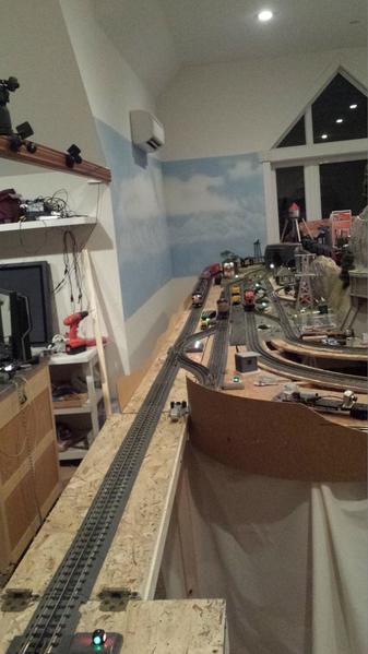
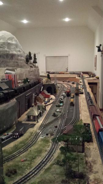
I have a z 4000 transformer  Output 1 feeding a tiu through  a fixed output on a large track. The track has 8 engines/trains sitting on various spurs and yard tracks. Very few of the rolling stock have lights.

The output 2 drives TIU channel 2 fixed output to another large isolated but interconnected oval of sorts.

A second brick power supply powers TIU variable  1 in  DCS mode to another large interconnected but isolated oval.

With the engines off, the amperage on output 1 of the transformer shows 3.1 to 3.4 amps. I do power the turnouts on this track( with track power) but when I remove the switch blocks from the turn outs nothing changes. All trains start up and function normally. The exception is if just I startup 6 or more engines one at a a time the current ramps up  to 8 amps indicated on the Z4000 readout. The seventh engine start shuts down the transformer.

I guess I can understand the too many engines issue, but what can be causing the 3.4 amps with nothing running. Or is this typical.

I don't remember seeing this before until just recently. Any suggestions where to look for the power draw. A few accessories are connected to the accessory post on channel 1 but they are mostly LED's.

Skylar

.


Original Post

Replies sorted oldest to newest

If you unplug the Z4000 from the TIU channel input, does the amperage reading go to zero? If so, then try plugging it back into the TIU input, and unplug the track from the TIU output, instead.

If unplugged from the TIU inputs the amp draw stays high, there's a problem with the Z5000.

If, instead, when the Z4000 is plugged into the TIU input and the TIU output is unplugged from the tracks, and the amp draw stays high, there's a problem in the TIU.

If the amp draw stays high only when everything is all plugged in, then something in the layout is causing the high amperage.

The amp draw seems way too high. Two tinplate 400e engines and a lighted caboose on my loop draws .5 amps at idle through the TIU. When running, it only increases to 1.8 amps pulling a bunch of cars with smoke units on.

The switches on your track should not draw much power when not in use.  This sounds more like a short.  Are you sure your loops are isolated?  How are you connecting wires to the transformer and track?  Maybe there is a stray wire strand? 

Barry, George thanks for the quick responses. Barry I will check as you suggest, I have noticed lately that the TIU receives commands OK from the remote, but does not seem to be transmitting back to the remote, When the remote is set in the normal mode instead of Speed mode there are a lot of delays sometimes and check track messages. Have you seen cases where the RCVR works but the transmitter does not with a unseated radio card in the TIU?


SKYLAR,

    You may have one of the 1st Z4K Transformers, I actually own one of them myself.  It shows almost 3DSCN1705 Volts on the read out screen, even when the handles are zeroed out.  The calibration on these 1st Generation Z4K Transformer, can float out of Calibration with the Read Out Screen.   To test it, set your screen read out at 18V, then test your actual track Voltage using a Mini Digital Clamp Meter,  you can pick one up Cheap at Harbor Freight, then compare your digital screen read out, to the actual Track Voltage, registered on your Mini Digital Clamp Meter.  In my case when I set the screen read out to 18V, the actual track voltage is about 16.  So when I want to run my Track Voltage at 18V to operate my Legacy & P2 engines, I must set my read out on the Z4K Transformer at 20V on the read out screen.  I have marked this difference in Red Marker on the Front of this particular Z4k, to identify it for all future use.   Your Z4K Transformer may have the same problem.  MTH can recalibrate the transformer, if you so desire, I use mine as is. 

PCRR/Dave

Attachments

Images (1)
  • DSCN1705
Last edited by Pine Creek Railroad
skylar posted:

I have a z 4000 transformer  Output 1 feeding a tiu through  a fixed output on a large track. The track has 8 engines/trains sitting on various spurs and yard tracks. Very few of the rolling stock have lights. 

I realize skylar said this issue may have just started, so this question may not be applicable.  Barry's trouble shooting guide should be done to see what is going on.

It sounds like the engines are in stealth mode.  How much power does an engine in this mode draw?  Also, if the lighted cars don't have LEDs they could be drawing quite a bit of power themselves.  Could the channel be normally pulling that many amps just sitting there?

When the remote is set in the normal mode instead of Speed mode there are a lot of delays sometimes and check track messages. Have you seen cases where the RCVR works but the transmitter does not with a unseated radio card in the TIU?

That's often either due to either low DCS signal strength, or a loose transceiver board in the remote, TIU or both.

You can rule the second possibility in or out by connecting (tethering) the TIU and remote with a 4-conductor telephone handset cable.

This and a whole lot more is all in The DCS Companion 3rd Edition", available for purchase  from many fine OGR advertisers and forum sponsors, or as an eBook or a printed book .

Last edited by OGR CEO-PUBLISHER

Thanks for all the inputs.

Just to clarify, all trains run in DCS mode fine until I power up more than 6 trains on one block powered  by Z4000 with output 1 and Tiu fixed track 1. Then the transformer shuts down because of obviously too high of current draw.

I have performed Barry' s suggested procedure and the results indicate that the transformer and TIU are normal.

However, setting I8v  on the transformer readout can vary the out put from 16.5 to 17..8 v directly out of the transformer. Although you can move the handle + or minus a few degrees  the readout stays showing 18v however the actual voltage can vary as described previously. Although the voltage readout has hysteresis the amp readout changes with the small handle movement as one would expect with a varying voltage.

The track voltage reads about 16.8 volts when the output of the transformer is showing 17.8v .

With all the engines removed and  all of the rolling stock with power pick ups removed from the track the amp readout is 1.0 amp at 17.8 volts. The only items powered are 20 Real Trax turnouts with the lighted switch blocks and about 6 end track bumpers lights. This would equate to around  .05 amps per turnout

Adding the engines to the track in a off state  adds a additional .2 amps per engine for a total of 1.8 amps. Is this because the battery chargers are being used ???

The total current draw is now 2.8.

Then I had all the rolling stock with power pickups and it adds an additional .6 amps.

This brings the total amp readout to 3.4 amps. 

Does any of this seem unusual to any one ?

I am considering adding another Z 4000 in a TIU passive mode to see if I can  reduce the amp load on the existing Z4000. I got this idea from Barry's DCS companion guide. Comments ?

Final question for Barry ,what command can I send  specifically from the remote that will test that the TIU transmitter is sending digital data correctly back to the remote..  I have used Track Signal quality, TIU version request and all return whether wireless or tethered what I would expect.  It seems  that the error messages that I sometimes receive are intermittent. Maybe as the TIU gets warm after several hours of use ?? I dont know. For the record the track signal quality is always 10. I use the star method of connecting from the TIU.

Skylar

skylar posted:


Adding the engines to the track in a off state  adds a additional .2 amps per engine for a total of 1.8 amps. Is this because the battery chargers are being used ???

The total current draw is now 2.8.

Then I had all the rolling stock with power pickups and it adds an additional .6 amps.

This brings the total amp readout to 3.4 amps. 

Does any of this seem unusual to any one ?

Now that you add it up, it seems about right.  That is a pretty big layout for one DCS channel and one handle on the Z4000.  Do I understand correctly that when you startup each engine the Amp draw goes to 8 Amps?  That seems a little high, but not sure I understand the full load on the tracks.  Once you get to 8 Amps, you are starting to push the limits.  When I had my full layout up with about 5 DCS engines and about 15 turnouts, I setup blocks and used all 4 channels of the TIU.  I set the variable channels to fixed.  I had a separate power supply on each channel making sure all were in phase.  The engines can cross over blocks between DCS channels and you don't even notice it.  This distributes the load on your transformers.  I recommend you leverage the whole of the system.

George

I am considering adding another Z 4000 in a TIU passive mode to see if I can  reduce the amp load on the existing Z4000.

Can you clarify?  The amperage draw from a transformer, whether in passive mode or feeding through a TIU, should be the same (slightly higher in latter mode if you're feeding TIU from Fixed 1 vice AUX).  You don't mean connecting the new TIU to the output of na TIU channel which has another TIU on the input side, I hope.  That's a no-no.

With nothing running, and no lighted cars, 3 amps is not typical.


You piqued my curiousity.  I went to my layout.  Fired up one channel on one handle of a Z4000.  Started up 8 locos (lots of noise).  Total amperage registered on the Z4000 was 2.9 amps.  All 8 were started, no smoke on (that DOES make a difference), but none were running.

Last edited by RJR

Are you using Var 2 on your TIU? You could set it to fixed and add a Z1000 brick or if you have another Z4000, you could run it off a channel on that.  Then you could split the power on that big yard.  

However, I do agree with RJR that you haven't described a load that would reach 8 Amps without a short circuit somewhere.  Is it always a certain engine that shuts the transformer down? Maybe there is a short circuit or something out of phase on that section of track?

George

I have 3 main lines each powered by its own channel of the tiu. No.1 output from transformer left handle,No 2 output from right handle and No 3. From a power brick.

I recently added a new.yard to park 4 additional  trains and I powered it with the tiu channel powered by the left handle. This is the channel that is 3.4 amps as described in the previous posts. I will not likely be powering up all 8 at once on this.circiit in normal ops but was surprised  I could exceed the limits with.all engines at idle

RJR

I am proposing to follow Barry's guide for hooking up an additional  transformer in a passive  mode to the existing tiu ie tie in at the output of the tiu instead of the input. I taken possession of an additional Z2000 which I plan to use for this is purpose.

RJR posted:

I am considering adding another Z 4000 in a TIU passive mode to see if I can  reduce the amp load on the existing Z4000.

Can you clarify?  The amperage draw from a transformer, whether in passive mode or feeding through a TIU, should be the same (slightly higher in latter mode if you're feeding TIU from Fixed 1 vice AUX).  You don't mean connecting the new TIU to the output of na TIU channel which has another TIU on the input side, I hope.  That's a no-no.

With nothing running, and no lighted cars, 3 amps is not typical.


You piqued my curiousity.  I went to my layout.  Fired up one channel on one handle of a Z4000.  Started up 8 locos (lots of noise).  Total amperage registered on the Z4000 was 2.9 amps.  All 8 were started, no smoke on (that DOES make a difference), but none were running.

I too tested in this fashion with 8 DCS engines (no smoke), 5 lighted cabooses, two lighted passenger cars (non-LED) and a some lighted lockons, upon applying power to the track I saw a spike to almost 3 amps that tapered off quickly to about 2.5 amps.  I didn't see any significant increase when I started all 8 engines (oddly enough, blowing the whistle on all 8 at the same time did result in a .5 amp increase). I too run my entire layout on one TIU channel but usually run only 3 or 4 engines at once and rarely use smoke.  My switches are all powered separately. 

Sounds like your layout is rather large, what gauge of wire are you using to power your track?  Keep in mind that lighter wire with long runs will create voltage drops and require more amps to run your layout.

Skylar, if you're reading Barry's book to say you can have 2 transformers feeding one track, you are definitely reading the book wrong.  How about citing the page you so read. Makes no difference if one is passive and one is active.  Two transformers should NEVER be used to feed one section.

You have something wrong, and you'd best find the cause.  Remove equipment from the track.  disconnect blocks of track, until the drain drops to 0.  If you have a wiring glitch so that 2 transformers are connected together, the drain could relate to that error.

H1000, if you're asking me, my layout is 14-gauge wire.  I actually run 6 channels, but only powered up one for the above test.

skylar posted:

George

was surprised  I could exceed the limits with.all engines at idle

RJR

I am proposing to follow Barry's guide for hooking up an additional  transformer in a passive  mode to the existing tiu ie tie in at the output of the tiu instead of the input. I taken possession of an additional Z2000 which I plan to use for this is purpose.

I would not try this.  I think Barry's book is referring to a different situation.  Troubleshoot the root cause, which sounds like a short, or split the big yard into two blocks as I suggested.

George

Gregg posted:

Start disconnecting a few things until you find  the problem.... Usually it only takes one wire.. The hot..    

To Dave   If the calibration is out,  would the transformer still read  3 amps  with nothing connected or perhaps just a light bulb. Does yours?


While there could be a calibration issue, his transformer shuts down with 6 or 7 engines started up.  Even with all the rolling stock (I assume lighted) and turnouts, that seems like a lot of amps before a train even starts moving. I would bet there is a short or there is an out of phase transformer with a car bridging the two blocks.  There was a suggestion to disconnect the brick transformer from output 3. I would like to know if this does anything.

Could the terminals in the TIU possibly be coming loose on the inside?  Skylar, does the connection from the transformer to the TIU input feel warm?

This has been discussed recently, some with problems at first, then melting cases.

The RealTrax turnouts should be on AUX power at 14v. BobbyOGauge detailed an internal problem if you see any sparking when going thru the turnout.

John H,

   You are correct sir, I was talking Volts, however with the handles down on my 1st generation Z4K, as you see in the picture below, the Amp screen read out is .8 Amps and the Voltage read out is 2.7 Volts, does not matter whether something is on the tracks of not.  The Digital Screen Read Out on the Z4K is almost 3V lower than the actual delivered track voltage, when the handles are raised to any given voltage.  He may have a 1st generation Z4K, like mine, that is causing part of his problem.  Note the handle of the Transformer on the right is set to 21V to get Approx 18V in reality, the right handle on the Transformer is down fully, note the digital read out as being 2.7V and .8 Amps prior to even raising the Transformer Handle.  The Calibration on the Z4K has floated out that much. Further each one of these 1st generation Z4K Transformers seems to float out of Calibration just a little differently, for some unknown reason and here is the strange part, while during actual train running from time to time, can look at the Voltage Screen read out, and instead of reading the 21V it was set at, for achieving the 18V track side, the read out will actually read the correct 18V on the Z4K screen, and it will be delivering the correct 18V to the tracks, later it will go back to showing the 21V on the screen and the track voltage will be still be 18V.   These 1st generation Z4K Transformers maybe female.  

PCRR/Dave

DSCN1705 


Attachments

Images (1)
  • DSCN1705
Last edited by Pine Creek Railroad

Everyone  I appreciate all the inputs.

John H.  The voltage  output measured with a Volt meter at the terminals posts is within .5 v of the readout. There is a lot of slop in the handle position and the readout. You can read 18v while still moving the handle and the out put actually varies +- .5v when measured with a meter. I don't believe this has any effect on my issue or maybe no issue. However I appreciate your brainstorming.

For all of you who suggest I have a short. 

I have removed every device off of the Track in this block with the exception of 20 turnouts. The Amp readout is 1.0 volts. I have the turnouts powered on track power not accessory power. I know this seems like a dumb approach but I found that the Real TRAX turnouts were sluggish at 14 volts. I run my track at 18 volts. So It seems reasonable that @ .05 amps per turnout ,1.0 amps  would be reasonable for 20 turnouts.

RJR 

I don't see how I would ever see 0 amps with my configuration. Even if there were no shorts. I am going to get a power block to power just the turnouts in which case I would expect to see close to 0 amps on the block. I have around a 100 ft of track on this block and I use the star connection method on the track power distribution and I use a combination of 14 and 16 gage speaker wire for the star connections. I will investigate the use of all 16 gage wire,

In reference to using 2 transformers in parallel. I believe from other electrical technical data (not model railroad papers) it is possible to use 2 identical transformers in parallel as long as they are at the same voltage and correct phase. Having said all this , there is probably good reason not to do it in this application. So the obvious solution is to power up the 4th channel on the TIU with this additional z4000.

To all  I think I may not have a problem after all, except for poor utilization of power distribution from the TIU and powering all these turnouts from track power. As my layout grew I was being a bit cheap and saving wire costs and over 8 years incrementally  got my self in this position.

Thanks for all your inputs this has been a worthwhile Topic for me and hopefully for others who are starting a project.

A few pictures.

Skylar 

Here a a few pictures .20160129_190859


P1010176P1010156


P1010194P1010159P101015720160129_19065220160129_190836


Attachments

Images (9)
  • 20160129_190859
  • P1010176
  • P1010156
  • 20160129_190859
  • P1010159
  • P1010157
  • P1010194
  • 20160129_190652
  • 20160129_190836
skylar posted:

Everyone  I appreciate all the inputs.


In reference to using 2 transformers in parallel. I believe from other electrical technical data (not model railroad papers) it is possible to use 2 identical transformers in parallel as long as they are at the same voltage and correct phase. Having said all this , there is probably good reason not to do it in this application. So the obvious solution is to power up the 4th channel on the TIU with this additional z4000.


Nice layout!  Maybe that Coors Light train is sucking all the Amps. It takes a lot of power to get that arctic chill.

i think you are correct electrically that you can parallel two transformers, but you are trying to exceed 10 amps on the circuit and will likely 'weld' some rolling stock and fry some engines in the process assuming the breakers don't trip anyway.  Not sure how this works as there is no regulator distributing the load to each transformer.

As I quickly read the above, you still haven't solved the cause of the drain.  It is of course your layout to do with as you will.  But I think you're making a major error in not tracking down the cause.  It may come back to bite you some day.

FYI< I have been told, but have not verified, that if 2 Z4000's are paralled, they will shut down.

Skylar,

I agree with George S on the two transformers being used as it would double the amperage available. The electronics in the engines also might be damaged with that current.

It should be easy to use another channel of the TIU as you are using star wiring. Just place another terminal block near the one in use. Then depending on how you have your trains dispersed on the original channel, move some of your wiring over to the new terminal block wired to the new channel. Maybe every other block or sections of blocks moved over to the new channel.  

As some people have pointed out in the past, I am wrong once in a while  However, I'm going to stick with my original post.  I see Coors Light cars, several postwar-like passenger cars, and per the OP several MTH engines in stealth mode.  All of these draw power (actually, not sure about the Coors cars).  If all of those are on the powered track, even just sitting there, then I think 2.5 amps or so shown on the transformer would be about right (or one amp with just the switches*).  The other issues brought up are a different story.

* ADDED: forgot the switch only scenario.

Last edited by CAPPilot

Interesting... How many MTH switches are on track power .?

 One bulb in the switch target and one in the controller,. So 2 bulbs  for each  switch times  20 switches  = 40 bulbs .   I have no idea how many amps  that would be.     However Skyler may not be using the switch controllers?  back to 20 bulbs.. seems he has a computer controlling his trains, perhaps switches as well.

Add Reply

Post
The DCS Forum is sponsored by

OGR Publishing, Inc., 1310 Eastside Centre Ct, Suite 6, Mountain Home, AR 72653
800-980-OGRR (6477)
www.ogaugerr.com

×
×
×
×
Link copied to your clipboard.
×
×