Nice work Jerry!
Rich


|
|
Nice work Jerry!
Rich
Jerry,. WOW!!!!!
That is beautiful work.
When I do these conversions I don't use a diode, I use a full wave rectifier, it's very small also less than 1/4 the size of the converter and rated at 1 amp, plenty for the strip of LEDs , the rectifier will allow you to reverse the polarity with no loss of the lighting. The strips are made for 12 v DC and with the converter you can adjust them for the brightness you desire they, the strips, also come in a variety of colors.
Ray
Rayin"S" posted:Jerry,. WOW!!!!!
That is beautiful work.
When I do these conversions I don't use a diode, I use a full wave rectifier, it's very small also less than 1/4 the size of the converter and rated at 1 amp, plenty for the strip of LEDs , the rectifier will allow you to reverse the polarity with no loss of the lighting. The strips are made for 12 v DC and with the converter you can adjust them for the brightness you desire they, the strips, also come in a variety of colors.
Ray
Thanks for the compliment. There's a LOT of work in these cars. Five of them are standard coaches, and one is a "smoking" car with a special section for smokers. All of the interiors are three shades of blue, so LEDs look more blue than they are in actual life. I'll tint the ones I have with some clear orange to soften them up a bit. Lowering the brightness will help too. BTW, I ordered those buck converters and will report on how they perform. Here's hoping...
As to the diodes, I use full wave rectifiers too, but all they are is a few diodes. And I've had one in the bridge fry on two occasions. That's why I am hesitant to install one in the roof. So I usually isolate the rectifier somehow so if it does fry, no plastic is nearby.
Hey guys, Happy New Year! Hope your Christmas time was a great one.
Jerry as always, your work is outstanding. It’s the kind of modelling I would like to be doing but know I will never get to it. Just curious, when you said you ordered the buck boosters are you talking about the mini’s Ray posted?
And I should have memtioned, the Brunswick green Flyer K5 in my Xmas videos was done by Jerry. Like all his work, it is beautiful and thanks again.
Happy New Year (I hope) to all,
Tom Stoltz
in freezing rain Maine
Tom Stoltz posted:Jerry as always, your work is outstanding. It’s the kind of modelling I would like to be doing but know I will never get to it. Just curious, when you said you ordered the buck boosters are you talking about the mini’s Ray posted?
And I should have memtioned, the Brunswick green Flyer K5 in my Xmas videos was done by Jerry. Like all his work, it is beautiful and thanks again.
Happy New Year (I hope) to all,
Tom Stoltz
in freezing rain Maine
Hi Tom,
Thanks for the compliment. Yes, the buck boosters are the ones Ray suggested. For the price, you can't beat it, and you know I'm cheap. I'll let the list know how they turn out in my application. If Ray suggested them, they're going to be good.
Happy New Year to you and Nancy, my friend!
Jerry
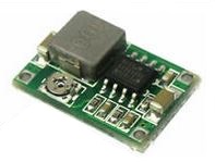
A little over a week ago, I ordered the mini regulators that Ray suggested. They came in 5 days! I ginned up a temporary circuit to test them out. Just what I was looking for! The module measures 17x11x3.8mm. I also got a few full wave bridge rectifiers and some 470μF 50volt caps for the circuit. I assembled it with a slew of alligator clips, and it works great. The caps smooth out the voltage to the LED strip to light the LEDs better. I have them adjusted to around 9VDC and they look great. With the size of the regulators, rectifiers and caps, they could be hidden in the S scale bathrooms! The rectifier and regulator on one side and the cap on the other. I'll power the circuit for a few hours on the bench before I stuff it all in the cars, just to be on the safe side. I want to see if it generates a lot of heat, or if a component will fry. When I finally install the circuitry, I'll post a photo or two.
Here's a shot from the bottom of the shell of what kind of room I have in the bathrooms. Just enough for the caps and other circuitry, The bulkhead with the bathrooms slides in the shell along channels on the shell, and is removable. The circuitry will be installed, then the bulkhead slid into place:

The small squares are drilled and tapped to screw the floor/chassis in place. A two pin mini connector will allow shell removal if necessary.
Thanks again, guys, for the suggestions!


Jerry, Good to see that you can hide the components in the bathroom
Ray
Ray and Jerry -- the link to the eBay converter provided by Ray earlier goes to this label: "JacobsParts Mini360 DC Voltage Step Down Power Converter Buck Module" -- based on both the title and the specs in the listing, this is a buck module only, not a buck-boost module. So if you are running Legacy or TMCC (?), etc. at a fixed AC track power (usually something like ~18 V), then a buck module should be all that is needed. So this device would work, as would the device that GRJ devised - which has the added advantage that it does the AC-DC conversion on the same board (widely discussion on other OGR fora).
However, if one is running conventional variable AC, then a buck (only) converter might work if the LED strip lights work at something like 4 VDC, since the track voltage is - for most practical purposes - going to vary between ~4 VAC and ~16-18 VAC. In this case, a buck converter will operate 'correctly' and simply step the voltage down to a user-set constant output voltage (that is always lower than the supply voltage). But if one uses the common LED strip lights that are spec'd at 12 VDC ( and perhaps operated around 9 or 10 volts to control the brightness) with variable AC track power as input to the buck converter, there will be times when the supply voltage is less than the output voltage set point for the buck converter; in that case the buck converter output goes to zero (or near that).
A search for buck-boost converters on eBay will yield a lot of (mostly Chinese) buck boost boards that I'm sure would work - though I haven't seen any that are very small, which is one of Jerry's requirement for his coaches. My assumption is that a lot of the buck and buck - boost boards that operate in the ~1 to ~20 VDC range and seem to be widely available on eBay and Amazon are designed for automotive systems. I wonder if these are 'over-spec'd' compared to what the requirements are for a board used to control voltage to an LED strip for lighting model railroad passenger cars. I'm not enough of an electrical engineer to know that - but perhaps there are circuit diagrams, etc. for a buck-boost system that meets the needs of the model railroad community - including small size.
- Rich
ps Jerry - the car interiors look fantastic -- the couple of close-up shots you posted are indistinguishable from the "real thing".
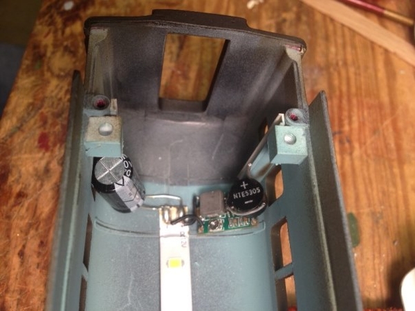
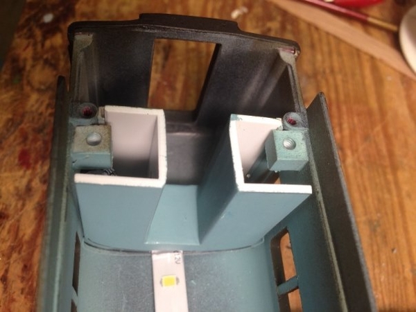
Now that I've completely hijacked this thread (![]() ) I'll show what the results of my testing on the buck modules produced. I bench powered the circuit for HOURS and no heat. So here are the components installed. The pencil marks show where the drop-in vestibule goes and how much room I have. The bare wires from the rectifier are where I'll solder on a two-pin connector about 4" in length so I can remove the shell from the frame if necessary. The second photo is with the vestibule in place, and hiding the circuitry. The LEDs start at about 6V and stay fairly consistent up until 9V where they reach maximum brightness:
) I'll show what the results of my testing on the buck modules produced. I bench powered the circuit for HOURS and no heat. So here are the components installed. The pencil marks show where the drop-in vestibule goes and how much room I have. The bare wires from the rectifier are where I'll solder on a two-pin connector about 4" in length so I can remove the shell from the frame if necessary. The second photo is with the vestibule in place, and hiding the circuitry. The LEDs start at about 6V and stay fairly consistent up until 9V where they reach maximum brightness:
Admittedly, a buck booster would be ideal, but this is a good enough substitute.


poniaj posted:Now that I've completely hijacked this thread (
) I'll show what the results of my testing on the buck modules produced. The LEDs start at about 6V and stay fairly consistent up until 9V where they reach maximum brightness:
Admittedly, a buck booster would be ideal, but this is a good enough substitute.
Jerry, as always, superb work. I am in awe of the modeling you do. And I’m very interested in this whole buck-boost thing, but still confused about what it is. I looked them up in Wikipedia and was left in a daze. I sort of though the buck was a voltage regulator while the boost is like a voltage amplifier.
Why I’m interested is I run DC and I run the trains slow. That leaves almost no lighting in the passenger cars. So this looks like a simple way to brighter, constant lighting. However, I get the feeling that the buck you used – without the boost – does not have constant lighting… if I want constant lighting I would need to use the one that includes the boost – is that true?
If I made this modification to the lighting, what impact would there be if I went to DCC in the future? My main reason to consider DCC is to get sound (I can’t hear the choo-choo anymore – even with hearing aids) and lighting… Probably asking for too much.
Tom
Tom, the buck booster will not give you constant lighting, to get that you would need either a control system that keeps power on the track or install battery in the car. If you are concerned about the flickering while running l added a 1000 mfd capacitor to the circuit.
Ray
Ray -- I'm missing something in your response to Tom...? Doesn't a buck-boost system provide constant voltage (usually an adjustable set-point on the output voltage) - so it should provide constant light levels - or something close to it, should it not?? It won't if the track isn't powered, but I don't think that was what he was asking(?).
Tom - The boards I have seen on Amazon or eBay are typically DC in to DC out, so at least in your case, you won't need to use a bridge to convert AC to DC. A cap across the input would help with any flickering.
richs09 posted:Ray -- I'm missing something in your response to Tom...? Doesn't a buck-boost system provide constant voltage (usually an adjustable set-point on the output voltage) - so it should provide constant light levels - or something close to it, should it not?? It won't if the track isn't powered, but I don't think that was what he was asking(?).
Tom - The boards I have seen on Amazon or eBay are typically DC in to DC out, so at least in your case, you won't need to use a bridge to convert AC to DC. A cap across the input would help with any flickering.
I probably used the wrong term, maybe I should have said consistent, brighter lighting. What I’m experiencing is that running the trains at such low voltage there is virtually no light in the passenger cars. What I was getting from this thread is the buck and buck-boost appear to increase the voltage available to the cars and the LED requires less voltage to begin with. Or so I thought.
Jerry is using a buck without the boost – what does that mean for the lighting? I’m also curious about going to DCC in the future. What impact would that have on a buck-boost system?
Tom
Tom - first, a disclaimer - I know, in general, how these work and I've spent some time trying to figure out the best way for me to retrofit my AF passenger cars and cabeese with LED lights and a circuit to provide both constant (and hopefully flicker-free) lighting levels - all while running with conventional variable AC track power. However, I haven't actually done anything yet !! - so you can size the grain of salt with which to take the following (hopefully it won't be too big...![]() ).
).
As the names imply, a 'buck' converter steps the DC input voltage down to whatever fixed output level you choose - even though the input voltage may vary. For our purposes, these are typically in the range of several to maybe ~18 - 20 V on the input side. The output side - assuming you are driving an LED strip light or string - is typically 12v (DC), although some of the folks here report reducing the voltage to ~10 v to reduce the brightness. The main point here is that for a buck converter, the input voltage ALWAYS has to be higher than the output voltage. So if the output voltage is ~10 to 12 V, the track voltage needs to be higher than that - which I suspect is much higher than what you run. I'm not sure what happens when the input voltage is less than the output voltage on one of these boards - I assume it simply stops working and the output goes to zero.
For a 'boost' converter, the opposite happens - namely the converter steps the DC input voltage up and the user-selected output voltage is ALWAYS higher than the input voltage. Again, the input voltage can be variable, while the output voltage is constant. This type of converter is likely to be the most useful for your situation - namely low track voltage for running the trains but still wanting to have ~10-12 VDC for lighting. HOWEVER, in the event where the track voltage goes higher than output voltage set to ~10 to 12 VDC, then I'm not sure what happens - either the converter stops working and the output voltage goes to zero or it stops working and the output voltage goes up with the input voltage, which could damage the LEDs.
So a 'buck-boost' converter is the merger of these two into one board. So the track voltage can now vary between zero and - say - 18 VDC and the board will provide a constant voltage output (e.g., ~10 to 12 VDC to light an LED strip). Here is a somewhat lame, but the best I could find quickly, YouTube presentation on these three types of converters. I don't know why these guys (and they are almost always guys) all have British (or maybe Aussie?) accents and speech mannerisms, but... if you can get past the tedious points, it illustrates what I've tried to describe above: https://www.youtube.com/watch?v=9--_jaxiXhE. If you want to cut to the chase right away, the buck-boost discussion starts around 11 minutes in.
One other consideration - you don't say (as I recall) whether you use (or plan to use) LED lighting or whether its incandescent. If the latter, you might be able to get away with only a boost converter with the output set at a voltage you are likely never to exceed on the track (like 16-18 VDC). The incandescent bulbs can handle those higher voltages, although if its too high, then the lights may be brighter than you want and then you are back into 'buck-boost' territory. The issue, as discussed in the youTube presentation, will then be how much current and wattage the boost or buck-boost converter will need to supply for the incandescent bulb. My thinking has always been to convert to LED lights - much lower current draw and more uniform lighting along the length of the car, etc. So then its "just" a matter of finding the right buck-boost board that is small enough to fit inside the car. Unlike Jerry and others - who've detailed out the car interiors (spectacularly) - I'm staying with the old paper diffuser look, so I don't have a "hide the board" problem.
Tom,
Rich has it correct, as far as I can determine. I am using the buck module as a voltage regulator. I have it set at 9V to keep the LEDs from being too bright. They start illuminating around 5-6V and rapidly go to full brightness with the cap I have in the circuit. Granted, I too would like them to illuminate at a lower voltage, but I can't fit all the electronics of a buck booster in my NH cars. So what i have till do. I will be pulling them either with an AC Flyonel EP-5 (which runs on at least 5V) or a pair of DC powered DL-109s. In the later case, the train will have to be going fairly fast to allow the LEDs to illuminate. I may install a resistor in the circuit on the locomotives just to allow more light in the cars, but that's a while away. IN any case, the buck module will also allow me to use them on a layout with DCC or even FlyerChief, both of which give a lot more voltage to the track while some sort of decoder drops and powers the locomotive at a variable speed. At least that's the plan... ![]()
Tom,
One thought for you, running DC power, you mentioned you run at low speed. Might you consider using LEDs ? The strip LEDs that most of us use are set to operate at 12 volts, you might assemble your own LED lighting using individual LEDs with a buck converter adjusted to limit the output to around 3 volts. I would still use the rectifier in the circuit, if you do reverse the polarity the cars will light in both directions.
Ray
Ray - you make an interesting point - if one is running DC and then reverses the polarity to back up, what happens to the lighting and more specifically the converter board? The boards have definite positive and negative inputs so I suppose reversing the polarity risks frying the circuitry? You suggest that using a bridge rectifier feeding the circuit - even though the track power is DC so no AC to DC rectification is needed - will still maintain the right polarity feeding the lighting board even when the input polarity is switched. Good idea - I had only thought about rectification in the context of AC to DC conversion.
I covered this point in an earlier post that also has the answers to a number of questions asked in subsequent postings. I think that any modification should consider use on AC, DC, and DCC operating systems in order to make the lighting work no matter on whose track the cars are going to run. The manufacturers take this flexibility into account in their products, and both Lionel and MTH have wisely taken this approach in the more recent locomotives, too.
- a bridge rectifier to allow the passenger car to run on AC as well as DC. It is necessary to keep the LEDs illuminated when you change DC polarity to reverse an engine. (Without the rectifier, the lights would go out when you back up because reversing changes the positive DC track wheels to negative DC and the negative wheels to positive. The rectifier keeps the output current the same polarity even if the input changes. ) Rectifiers cost about $0.44 each.
TOKELLY posted:I covered this point in an earlier post that also has the answers to a number of questions asked in subsequent postings. I think that any modification should consider use on AC, DC, and DCC operating systems in order to make the lighting work no matter on whose track the cars are going to run. The manufacturers take this flexibility into account in their products, and both Lionel and MTH have wisely taken this approach in the more recent locomotives, too.
- a bridge rectifier to allow the passenger car to run on AC as well as DC. It is necessary to keep the LEDs illuminated when you change DC polarity to reverse an engine. (Without the rectifier, the lights would go out when you back up because reversing changes the positive DC track wheels to negative DC and the negative wheels to positive. The rectifier keeps the output current the same polarity even if the input changes. ) Rectifiers cost about $0.44 each.
I thought Terry did make this clear before. Switching polarity is the main feature of running DC. So unless the buck-boost can handle reversed polarity, a rectifier is a must. My main question was how to think about the buck and boost. Rich, I did try to watch the uTube, but with my hearing and the accent plus my (lack of) knowledge about electronics, made it a real non-starter for me. However, I think my primitive interpretation is actually fairly close; that is think of the buck as a variable voltage regulator and the boost as a voltage amplifier.
Now the voltage amplifier part of this makes me think about throwing one of these at a smoke unit… any thoughts?
Tom
The basic white LED runs at about 3.5 volts. If you eliminate the built-in resistors in what ever LED string you are using, you can put in a voltage regulator and illuminate the LEDs at about 4-5 volts of track power. There is some overhead lost in the regulator.
If the input to the regulator from the track has a bridge rectifier (4 diodes in a bridge) the LEDs will illuminate on AC , DC+ or DC- track power and almost any voltage.
I see that Ray said basically the same thing.
Access to this requires an OGR Forum Supporting Membership
