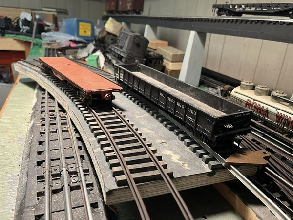
Bob, no scotch either! My oh my! 😄 Yes, that is what I often do, button it up for another day. I think you said you already tried a BCR, but I forgot. That white battery is old I believe. The new ones are green. I’ll write more on the forum later. Off to PT now.
@Mark Boyce posted:Bob, no scotch either! My oh my! 😄 Yes, that is what I often do, button it up for another day. I think you said you already tried a BCR, but I forgot. That white battery is old I believe. The new ones are green. I’ll write more on the forum later. Off to PT now.
Correct Mark- the photos are from when I first opened it up. It has a new speaker and GRJ BCR now.
Have fun at PT!
Attachments
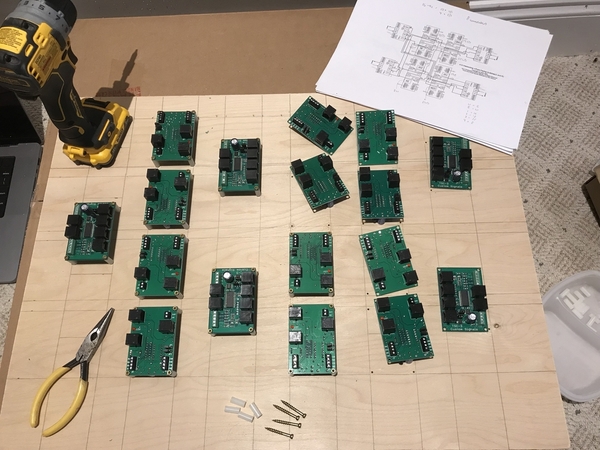
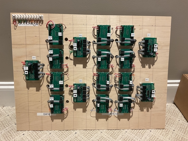
Time to connect the block signals! It's a slow process but it's rewarding in the end. There are a few extra boards to allow the signals to detect occupancy based on current route set by switches.
Attachments
So many options its a challenge making decisions on the layout rebuild.
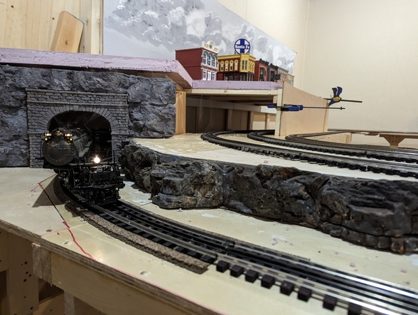
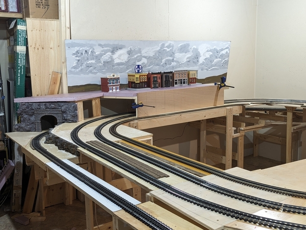
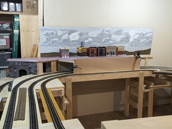
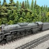
Here are a couple of photos of Twin Pines RR2. This is the section where the lower freight yard track approaches grade. I decided the town would be best placed above the main line tracks. I need to figure out the tunnel portal where you can see the C-clamp. I did get out my BigBoy to check clearances. The tender is the potential problem child as it has a string of fixed flanged wheels on a portion of it. I had done a decent job on the curves except at one section where the tender was binding slightly on an 072 curve. Easily fixed. I had forgotten how much smoke he puts out. For now just running conventional.
I plan to get this section in reasonable shape before I move on to other areas. That is HO cork roadbed sliced to fit next to the ties. I'll glue ballast to it but leave the tie ballast free flowing.
Attachments
Jeff, it looks like you are moving along nicely. The rocks look great! Nice plan for the ballast.
Fixed a nagging problem yesterday. I redid the yard in the middle of the layout a couple years ago. For those who remember, I cut down 3 MTH scaletrax 031's in order to fit 3 sidings over the 2 I had with 5122's. Despite all of my testing, I wound up with a dead zone between switches 1&2. Not only does this stall yard operations, I also use this as a reverse loop to turn trains around.
I was looking at it yesterday, rolling a MTH caboose with pickups on both trucks over the area and saw that it was about a 1/2" gap causing the stalls. So I decided I could add a section of center rail on switch 1 that should solve the problem. I added it on the outside of the diverging rail of the turnout. Still needs a little fine tuning but seems to have solved the problem.
The piece is between the right and center switches. The SW1's stalled every time before.
Bob
Attachments
@luvindemtrains posted:Is your signalling system from Custom Signals?
Dave
Yes, my signals are from Atlas/Custom Signals. Great product set.
progress: drilled holes for rj45 connections, wired the board cross-connects & installed/labeled the harness blocks ... so this board is ready for installation.
Next up is connecting power, wires for switch sense, wires from block insulated rails to the harness, then the rj45 cables to the signals.
Attachments
@ScoutingDad posted:I need to figure out the tunnel portal where you can see the C-clamp. I did get out my BigBoy to check clearances. The tender is the potential problem child as it has a string of fixed flanged wheels on a portion of it. I had done a decent job on the curves except at one section where the tender was binding slightly on an 072 curve. Easily fixed.
Jeff, You are making great progress! Would it be possible to shorten that tunnel wall a bit to get it back from the curve? Make the portal slant in toward the outer wall.
@ScoutingDad posted:So many options its a challenge making decisions on the layout rebuild.
Here are a couple of photos of Twin Pines RR2. This is the section where the lower freight yard track approaches grade. I decided the town would be best placed above the main line tracks. I need to figure out the tunnel portal where you can see the C-clamp. I did get out my BigBoy to check clearances. The tender is the potential problem child as it has a string of fixed flanged wheels on a portion of it. I had done a decent job on the curves except at one section where the tender was binding slightly on an 072 curve. Easily fixed. I had forgotten how much smoke he puts out. For now just running conventional.
I plan to get this section in reasonable shape before I move on to other areas. That is HO cork roadbed sliced to fit next to the ties. I'll glue ballast to it but leave the tie ballast free flowing.
Using the ho roadbed gives it a much better look then a true prototypical 1/2-inch!!
Ron
@RSJB18 Bob, that looks like an excellent fix for the stalling problem on the switches!
@ScottV that is a handsome looking board for the Atlas boards!
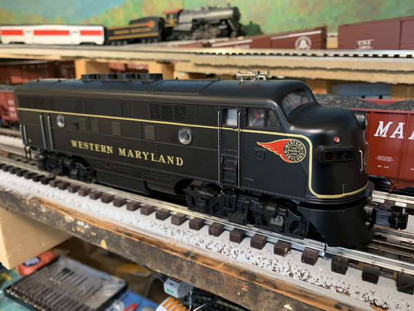
Yesterday I finished a PS3 upgrade on a 1995 Premier ProtoSound Western Maryland F3. The innards aren't pretty, as we discussed on my own thread, but it works! ![]() My only other upgrade was a BL2 that I did 5 years ago. I have a lot of trouble handling small parts and wiring, and next time, I will follow some advice from others. The only other upgrade is I added a much better looking crew of two to replace the original wimpy looking engineer.
My only other upgrade was a BL2 that I did 5 years ago. I have a lot of trouble handling small parts and wiring, and next time, I will follow some advice from others. The only other upgrade is I added a much better looking crew of two to replace the original wimpy looking engineer.
Attachments
Not on the layout proper. . .I went to Chicagoland Hobby to buy parts. They're closing in two weeks.
Thanks for the comments. I got the idea of using HO cork roadbed from an O modeling book. I can't find it otherwise I would credit the author. IMO using full roadbed or not is a matter of preference. I tried foam roadbed and was not pleased with minor variation in track height due to screwing down one section more than another. In TPRR1 the ballast was glued down and tapered. Removing the track resulted in some damage as I was a little heavy handed with the ballast glue, resulting in spots where the ties were firmly glued to the sub-roadbed.
Regarding the portals, the photos show the entire 12 foot section along the south wall. The inner loop narrows its clearance with the inner main at the clamp. Any movement further "left" (east) would make track to wall clearances under 2 inches - which I would like to avoid. Moving the inner loop "north" takes the curve into a future bridge and lift section. I would prefer to have the portals on a straight section but given the tight space I elected to put them on a curve - curve clearances are nasty. The elevated section will extend into the corner to the "right". Undecided on the portal locations at this point.
Bob, not sure about the meaning of "slanting in toward the outer wall". Does it mean push the lower portal back to be "even" with the "future" upper portal? Eventually I would like to have a trolley serving the town, even if its a point to point. Putting returning curves/loops in at each end is space constrained. Unfortunately the closet is claimed by the CEO meaning no more space to the left.
Attachments
@ScoutingDad posted:Thanks for the comments. I got the idea of using HO cork roadbed from an O modeling book. I can't find it otherwise I would credit the author. IMO using full roadbed or not is a matter of preference. I tried foam roadbed and was not pleased with minor variation in track height due to screwing down one section more than another. In TPRR1 the ballast was glued down and tapered. Removing the track resulted in some damage as I was a little heavy handed with the ballast glue, resulting in spots where the ties were firmly glued to the sub-roadbed.
Regarding the portals, the photos show the entire 12 foot section along the south wall. The inner loop narrows its clearance with the inner main at the clamp. Any movement further "left" (east) would make track to wall clearances under 2 inches - which I would like to avoid. Moving the inner loop "north" takes the curve into a future bridge and lift section. I would prefer to have the portals on a straight section but given the tight space I elected to put them on a curve - curve clearances are nasty. The elevated section will extend into the corner to the "right". Undecided on the portal locations at this point.
Bob, not sure about the meaning of "slanting in toward the outer wall". Does it mean push the lower portal back to be "even" with the "future" upper portal? Eventually I would like to have a trolley serving the town, even if its a point to point. Putting returning curves/loops in at each end is space constrained. Unfortunately the closet is claimed by the CEO meaning no more space to the left.
You and I were reading the same booklet! But before I found that booklet was designing what I hope to build/
Did not the look of 2-foot high prototypical roadbed. So started experimenting with 1/4-inch O gauge roadbed material which covered to much of the ties. Was thinking on trying S-gauge roadbed material but rad into that booklet. The HO material looked GREAT once ballasted!
Ron
@ScoutingDad posted:Thanks for the comments. I got the idea of using HO cork roadbed from an O modeling book. I can't find it otherwise I would credit the author. IMO using full roadbed or not is a matter of preference. I tried foam roadbed and was not pleased with minor variation in track height due to screwing down one section more than another. In TPRR1 the ballast was glued down and tapered. Removing the track resulted in some damage as I was a little heavy handed with the ballast glue, resulting in spots where the ties were firmly glued to the sub-roadbed.
Regarding the portals, the photos show the entire 12 foot section along the south wall. The inner loop narrows its clearance with the inner main at the clamp. Any movement further "left" (east) would make track to wall clearances under 2 inches - which I would like to avoid. Moving the inner loop "north" takes the curve into a future bridge and lift section. I would prefer to have the portals on a straight section but given the tight space I elected to put them on a curve - curve clearances are nasty. The elevated section will extend into the corner to the "right". Undecided on the portal locations at this point.
Bob, not sure about the meaning of "slanting in toward the outer wall". Does it mean push the lower portal back to be "even" with the "future" upper portal? Eventually I would like to have a trolley serving the town, even if its a point to point. Putting returning curves/loops in at each end is space constrained. Unfortunately the closet is claimed by the CEO meaning no more space to the left.
Jeff,
I drew a line on your wall. Obviously I have no idea how many inches that is from the edge. Just suggesting if you move the end of that wall just enough to get better clearance I don’t think that it would have much of an impact on your upper level. 
Attachments
@Mark Boyce posted:Yesterday I finished a PS3 upgrade on a 1995 Premier ProtoSound Western Maryland F3. The innards aren't pretty, as we discussed on my own thread, but it works!
My only other upgrade was a BL2 that I did 5 years ago. I have a lot of trouble handling small parts and wiring, and next time, I will follow some advice from others. The only other upgrade is I added a much better looking crew of two to replace the original wimpy looking engineer.
Mark:
You doing your own PS3 upgrade is impressive. How did you learn to do the upgrade? Are you a trained MTH repair technician? If not, how did you get access to the MTH sound files?
Great work. Bravo!
Bob, OK got it. The detail is, the upper level at that point has about an inch between the ties and the plywood edge. Right about at the line is where the lower spur track is about an inch (horizontal) from the upper level ply edge and the vertical clearance is about 4-5 inches. There would be no way to add a separating tunnel wall even if only cardboard. As is I can use the extra space to lay in a separating wall which should mostly hide the lower track when viewed looking into the tunnel portal.
I'll take another look at it and see if pulling the portal back as you suggest would work. If not straight, the portal going to be quite wide. The vertical mock up wall is 50 inches long with another 60 going into the corner. Top is 23 inches deep. The BigBoy swings quite wide but it least the biggest swing is at the leading edge (not the cab like with the RailKing version).
@Mark Boyce If you're commenting on the finish quality of those boards, they're a finer finish than I'd normally use for something that's under the layout and out-of-sight. .....but.... those boards were actually the least expensive alternative to either plywood or masonite. A local art supply store had a sale on the boards and they're the perfect size.
Added a new pond to the layout last weekend. Third one so far!
@Randy Harrison posted:Mark:
You doing your own PS3 upgrade is impressive. How did you learn to do the upgrade? Are you a trained MTH repair technician? If not, how did you get access to the MTH sound files?
Great work. Bravo!
Thank you, Randy! All I did was follow the excellent instructions that can be downloaded from the MTH Website. However, since I was trained as an electronics technician and worked in that field for 43 years, I was familiar with processes, tools and materials, and precautions. No, I am not a trained MTH repair technician, but the sound files can be downloaded from the MTH Website also. In this case, I had to do some searching for an F3 release that has PS3, so it took a bit of digging. The MTH Website has nice videos to show how to download and install the MTH Consumer Loader onto your PC. They show what cable you need, in this case I used a regular USB cable connecting my laptop to the TIU. The videos show how to find the sound files. All that said, I found it to not be intimidating. For someone who doesn't have any background in electronics, then having a trained MTH technician do the upgrade would probably make sense. The boards are factory tested and sealed in static wrap. Once you break the seal, there is no warrantee on the board. That's the big chance you take with the consumer upgrade kits.
@ScottV posted:@Mark Boyce If you're commenting on the finish quality of those boards, they're a finer finish than I'd normally use for something that's under the layout and out-of-sight. .....but.... those boards were actually the least expensive alternative to either plywood or masonite. A local art supply store had a sale on the boards and they're the perfect size.
Scott, you do the same as me. I have quite a collection of old and new wood on my layout. Whatever it takes if the price is right. I like how you laid out the board with all the lines drawn to line up the separate units and wiring. I always try to have things lined up and as symmetrical as possible, though my hand isn't as steady as I like, so sometimes I live with something slightly askew.
Mark:
Thank you for your kind reply. I really appreciate this. I will give the MTH website a look.
Randy, here is the Website and you can see the different pages.
https://www.mthtrains.com/service
“For someone who doesn't have any background in electronics, then having a trained MTH technician do the upgrade would probably make sense. The boards are factory tested and sealed in static wrap. Once you break the seal, there is no warrantee on the board. That's the big chance you take with the consumer upgrade kits.”
That’s sound advice Mark. I was a switchman in NY Tel (today they are switching equipment technicians) during my time the system was electro-mechanical. Circuit boards were being introduced in certain applications. Your comment about the static bag reminded me about the wrist strap grounding me to the equipment prior to handling the board. All that makes me apprehensive to do my own work.
@Mark Boyce posted:The boards are factory tested and sealed in static wrap. Once you break the seal, there is no warrantee on the board. That's the big chance you take with the consumer upgrade kits.
@pennsyfan posted:“For someone who doesn't have any background in electronics, then having a trained MTH technician do the upgrade would probably make sense. The boards are factory tested and sealed in static wrap. Once you break the seal, there is no warrantee on the board. That's the big chance you take with the consumer upgrade kits.”
That’s sound advice Mark. I was a switchman in NY Tel (today they are switching equipment technicians) during my time the system was electro-mechanical. Circuit boards were being introduced in certain applications. Your comment about the static bag reminded me about the wrist strap grounding me to the equipment prior to handling the board. All that makes me apprehensive to do my own work.
I took a LONG pause before taking a knife to the seal on the stacker board kit I bought......![]()
Bob
@John's Trains posted:I second Steve at Rescued Trains comment: EXCELLENT!
Mike, did you design the mechanism for that takeoff?John
Hi John, sorry it to so long to get back to you, its been a little busy around here and it has nothing to do with trains! LOL
Yes I designed it , it is a motor from an old printer and some fishing line underneath it. I can try and get a couple photos for you!
Hi guys I hope you remember me,
It has been about 3 weeks since I was here last! As you can see from my post above it took me about 45 minutes to read everything that everyone had done since John's question came up! I know I have been reading here for about an hour and a half just to see what I have missed!
I would comment on everyone but that is even too much for me! LOL, I know some of you will be mad at me as I just handed out a whole bunch of likes and I guess your email is going to be full of them! LOL sorry! They wouldn't be there if you all didn't do such great work and had so much wonderful information to share with the rest of the group!
Just so you all know I have nothing new to share with you as it has been busy around here! But I am glad you all were able to share your joy of your layout and trains with me!
I hope you all have a great weekend and have fun with your layouts and trains! I am going to try and go work on some switch machines!![]()
Welcome back Mike, glad you're ok.
Steve
Thanks Steve, I was just out in the train room working on 5 switches and controllers from MTH. Some of the motors work and some of the controllers work. Only 2 of them as a team as intended! Lol lucky me, but I will work on them the next time I get a free moment.
Have a great weekend everyone! 😀
@pennsyfan posted:“For someone who doesn't have any background in electronics, then having a trained MTH technician do the upgrade would probably make sense. The boards are factory tested and sealed in static wrap. Once you break the seal, there is no warrantee on the board. That's the big chance you take with the consumer upgrade kits.”
That’s sound advice Mark. I was a switchman in NY Tel (today they are switching equipment technicians) during my time the system was electro-mechanical. Circuit boards were being introduced in certain applications. Your comment about the static bag reminded me about the wrist strap grounding me to the equipment prior to handling the board. All that makes me apprehensive to do my own work.
I worked a variety of jobs from the mid ‘70s to mid ‘80s. That was a tough time to get started working. Some jobs were cut short due to lack of work coming in, others were cut short due to companies completely shutting down. Some positions required working with state of the art electronics requiring grounded wrist straps, others did not. Then I worked in the power industry which was mostly electro-mechanical around higher current. We were downsized in 1995 and at the beginning of 1997 until retirement I worked for a regional telephone company and I was again exposed to concerns about static electricity like you.
@RSJB18 posted:I took a LONG pause before taking a knife to the seal on the stacker board kit I bought......
Bob
Bob, you are absolutely right. It was one thing to fry a board the company paid for, but quite another to risk frying one I paid for. When my understudy and I fried a solid state unit protecting a 500KV transmission line while the line was in service, we received a slap on the hand, but actually earned overtime pay retrieving a replacement unit and putting it in service. If I fried the PS3 board, I would be out $200. 😄
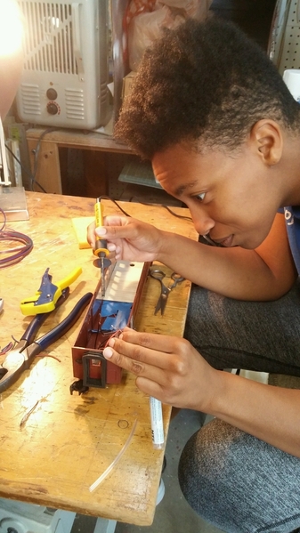
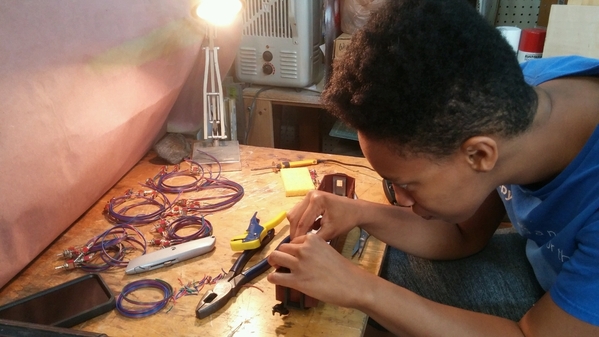
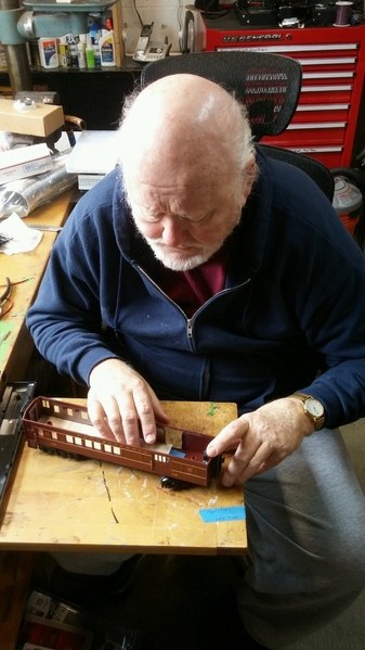
Layout progress for today, 9/10/2023, Zora Maya and I were hard at work this morning. The photo below shows the "Z" lady, queen of the soldering iron, doing electronic soldering.
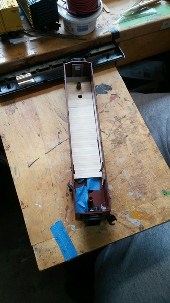
Though she spent most of her time soldering wire to SPDT momentary toggle switches for our control panel. In the above photos, she is doing some final soldering for the LED lighting in my PRR, Railroad Post Office (RPO) car that I am creating using a modified MTH, Madison, PRR, O-27, combine coach with a lighted and custom detailed interior. The LED lighting is from Gunrunner John's complete LED passenger coach conversion kit. I heartily recommend John's conversion system available through Henning's Trains, an OGR Forum sponsor.
Below, I am working on the wood planked floor of the RPO using a long, thin strip of wood that has the planking inscribed on it. the lines showing the planking did not pick up in the photos below but, are there and make for a good appearance in person.
Also, just a "heads up". I am not going to be posting next week. On Tuesday, 9/12/2023, I am having a laparoscopic surgical procedure that will require me to remain in the hospital for several days thereafter. However, I am borrowing one of my wife's laptop computers and will be reading the OGR Forum to see and enjoy all of your GREAT posts.
Attachments
Attachments
Attachments
@Randy Harrison posted:Also, just a "heads up". I am not going to be posting next week. On Tuesday, 9/12/2023, I am having a laparoscopic surgical procedure that will require me to remain in the hospital for several days thereafter. However, I am borrowing one of my wife's laptop computers and will be reading the OGR Forum to see and enjoy all of your GREAT posts.
Take care Randy. Hope all goes well.
@Randy Harrison posted:…..Also, just a "heads up". I am not going to be posting next week. On Tuesday, 9/12/2023, I am having a laparoscopic surgical procedure that will require me to remain in the hospital for several days thereafter. However, I am borrowing one of my wife's laptop computers and will be reading the OGR Forum to see and enjoy all of your GREAT posts.
Randy, best of luck with your surgical procedure. I’m sure everything will be fine. Say hello to Terry for Lynley and I!
@Randy Harrison posted:Also, just a "heads up". I am not going to be posting next week. On Tuesday, 9/12/2023, I am having a laparoscopic surgical procedure that will require me to remain in the hospital for several days thereafter. However, I am borrowing one of my wife's laptop computers and will be reading the OGR Forum to see and enjoy all of your GREAT posts.
Make sure Zora has plenty of ventilation in her soldering area .
And Randy , don't worry about getting back to the layout........give yourself the full measure of of recovery time . ![]() Best wishes sir.
Best wishes sir.
@Dallas Joseph posted:Make sure Zora has plenty of ventilation in her soldering area .
And Randy , don't worry about getting back to the layout........give yourself the full measure of of recovery time .
Best wishes sir.
Plenty of ventilation in the soldering area?!?! Getting in the Way-Back Machine no one said anything about ventilation!! Of course our lab instructor was a retired guy who checked for voltage with his thumb and finger. I believe he helped George Westinghouse get his business started… 😆 Kidding aside, good advice, Dallas!
@NSRailfan100 posted:
Super looking job!!! Let’s go Pens!!
No pics but I'm patiently working through all the room-prep "to-do" items, which for me includes prepping 3 windows that will be permanently closed-off when they're blocked by masonite backdrop panels, as well as doing the usual ceiling & lighting work.
Rich in WV.
@Randy Harrison posted:Also, just a "heads up". I am not going to be posting next week. On Tuesday, 9/12/2023, I am having a laparoscopic surgical procedure that will require me to remain in the hospital for several days thereafter. However, I am borrowing one of my wife's laptop computers and will be reading the OGR Forum to see and enjoy all of your GREAT posts.
Best wishes for a speedy recovery.
Peter


