


No images again, Myles.
Something's screwy. I've been uploading to this thread for over 6 years and basically do it the same way. I'll reload them. There were a ton of them!
Despite being no where near size limits, anything more than six files gives me issues at times over the years. Over ten, chances of failure doubled. The OS doesn't seem to matter (Win./ Droid anyhow. i stuff?.. ?)
Okay… I reloaded all of those pictures. It almost takes as long to reload as it does to write the post in the first place.
Today I have a ton more. Like I said, working on many aspects at once creates a lot of pictures. Each time I glue something with Titebond, I have to let it sit about 1/2 hour before de-clamping.
Today's production included finishing the pilasters and crane rail support installation on the left inner wall. I also cut, shaped and installed the upper supports for the roof trusses. I assembled the very slick laser cut railing for the gantry. I started sorting massive numbers of windows and figuring out my process. I pulled the clamps off the first gantry rail assembly and J-B Welded the other one, which will be cured tomorrow. And I tried the left wall's fit next to the floor and found two problems, both which offer some challenges.
I finished up adding the pilasters to the left inner wall, then glued on the 8 gantry rail supports. To make sure that these were level with each other I used a straight edge and periodically checked a reference location between the straight edge and the top of the 2nd level window openings. It didn't very more than a few thousandths.
The pilasters were keyed to the reference line I drew at the bottom accounting for floor thickness. BTW: I re-glued the end pilasters with their correct 1-wall-thickness offset.


While this was drying, using the new piece of 3/4" pine I bought last night, I cut pieces that conformed to the contour on the template pieces that I had cut. These templates came in handy! The bottom side is tapered for clearance of the gantry, and I put that new belt/disc sander to work. I was this particular part that I bought that machine for. At first I thought I would have to rough the stock off with the big belt, but the disc did just fine. It made a mess and I work a dust mask and goggles to keep from ingesting all that fine sawdust.
I set the miter gauge to match the template's angle and in a couple of passes took off all the stock.

After this I used the shop vac on the machine, the room and me. I don't have a dust collector system.
I used the template itself to set the gluing distance for the 14 truss supports. Notice that the gantry supports skip every other pilaster.

After all were glued I weighted them all at once with a big level and some gravity inducing items.

I will flip this over tomorrow and add the pilasters on the outside and that wall will be completed.
While this was drying I assembled the 3-part gantry railing. When I drew this I wasn't sure if it would be too delicate to cut, but Stephen used a good laser board and the details came out perfectly. It is a 3-layer sandwich. The center layer has the lattice and the outer two are duplicates that give it depth. This was cut on self-stick material and it went together very nicely. This will be painted "equipment yellow" after the gantry is assembled.


I set this aside for later...
I opened up all the window frets and will spray paint them while still in the frets. These too are self-stick. Lots and lots of windows, but assembly is really slick and Stephen has included pre-cut acetate too. Much less work than my previous buildings.

When the wall was dried enough to handle I set in in place adjacent to the finished floor and found two areas of concern. The most egregious is the floor ending up being 1/8" too short. I hate when stuff is TOO SHORT. That 1//8" number is suspicious telling me that I took one wall thickness to much off the part design. Remember, the laser never lies. Any measurement error is all mine. Darn! I will splice material on and it will be okay.
This is one end in its proper position.

Here's the shortfall.

The second problem is the gaps that were under the gantry supports. Something ain't right! But my gluing job was almost perfect as seen in this image.

But look at the alignment on the truss supports… Notice, I've tried on the gantry track rail. It lined up nicely.

Here's the problem… The ground ain't level… just like the real world. There is a dip in the platform under the yard tracks in this location.

I can't bring the floor up to join the buttresses since it raises it too far above track height and the big O'gauge flanges will ride up on the floor. I can shim under the buttresses so the gluing surface will be intact and let the floor follow the terrain. There's one other option which I will explore. This is an L-girder layout. I may be able to adjust the cleats and risers holding up the yard platform. I don't know how much give there is since there's some plastering in the area, but it's worth a try.
On another topic, my Kalmbach special issue on the resurrection of UP 4014 arrived yesterday and it's a terrific book. Seeing all the things that UP's steam crew did to make that engine alive again was nothing short of miraculous. A note of interest. UP's shop is world class, but to turn and quarter Big Boy's massive drivers they shipped them off to the Strassburg RR's steam shop who has a wheel lathe large enough to service 1940's loco's drivers.
I also did one more thing. I've volunteered to do a soldering demonstration for the Military Modelers Club of Louisville. I've been soldering photo-etched parts which is not something that many folks do. I also have perfected hand soldering those tiny surface mount LEDs. These are both topics of interest to plastic modelers.
Attachments
Images (13)


Myles, the project is looking great! I think the platforms on the outside would be sufficient to give the right look! I suppose if you don't like it and feel energetic later on, you could add ones between the tracks later. I was wondering if you can't raise the table top sufficiently, you could just put a sill under all those supports. Once in and painted, you will probably be the only one who would notice.
Thanks Mark! Yup! Could just dress up the buttresses, or just add a shim. I'm interested to find out if the raising the risers about 3/16" could take out the dip. The center section of the layout is the basically paved with OSB sitting on risers. In the center of the yard, the joint between two panels actually created a little hump. Not a real hump yard, just a teensy little bump, but I know it's there. Dips in the tracks in a yard don't matter. My main line track is pretty consistent.
Myles, yes I agree if you can raise the risers 3/16” that is best!
Too many images could be the problem… I generally don't have this many images, but usually don't have so many topics I'm working simultaneously.
Tried to raise the platform to remove some of the dip. Was marginally successful. I had to secure a block on the L-girder to give enough space for my Quickie Clamp to fit. The clamp's fixed jaw is reversible so it can function as a spreader, but it's minimum width was large than the space between the girder and the OSB. I loosened two risers in the vicinity and exerted as much pressure as I could on the clamp. It did move a bit. I reattached the risers in this new position, but it's still about 1/8" low in the wall's center. I'll shim the buttresses.
Here's the clamp doing its work. Spax star-head screws are terrific. Even though they don't need a clearance hole, I use them since it insures that the piece you're screwing to pulls up tight.

I flipped the wall over and started laying in the pilasters on the outer face. The end two are wider designed to extend out one MDF thickness to wrap over the pilasters that will go on the end wall. I used a piece of the same material to ensure that the offset was, indeed, perfect.

I started laying in the remaining pilasters and wanted to find a way to streamline aligning them to the wall and each other. I centered one of them as best as I could and glued it in. I then placed the next one and measure the distance which I transferred to a piece of the 3/4" stock and cut two gauges. These came out pretty close and I was able to use them to space the pilasters to that well-placed first piece.

After doing a couple of them, I noticed that I was getting some off-center drift and corrected alignment before clamping them down. My gauges may have been a few thou off the exact number and I was getting some stacking error, or there could be some minor variations between window spacing. Either way, I was able get the first half into position. Notice that the pilasters aren't reaching the bottom. This WAS NOT supposed to happen. It's due to using "one size fits all" mentality. For the inside pilasters, I needed that clearance to accommodate the floor. I also needed the same clearance for the machine shop floor. But I DIDN'T NEED THE CLEARANCE for all the rest of them. Easy fix… I have a scrap wall which Stephen cut a bit short. I measured the piece I needed and cut it off on the scroll saw. I don't have a circular saw. For long rip cuts I really miss that. The scroll saw doesn't cut a very true line. I made the piece a bit oversize and will sand it down flush after the glue dries. My mantra: "It's not if you make a mistake… it's how you recover!"

While this was drying, I prepared and painted all the windows while still in their frets. Since I was going to blast them with Tamiya lacquer-based primer, AND it actually wasn't raining outside, I taped the windows to some cardboard and went outside and painted them. I had to be careful to not tape over parts of the windows that would be seen.

This is Tamiya's rattle can Red Oxide primer. I'm thinking to just leave them at that. If I spray acrylic I can do it in the basement. My RR is a merger of the Pennsy and UP. That leaves Tuscan Red, Dark Green, Harbor Mist Gray or Armor Yellow as appropriate colors. I need to complete all the painting before assembling them.

Back to the Left Wall. The after part of the wall intersects with the Machine Shop. I needed to be sure that the pilasters didn't foul the mounting tab slot. I used the machine shop left wall as a positive stop to put in that pilaster. The fit is superb.

Then it occurred to me that the Machine Shop roof is slotted to clear the pilasters and therefore can be used as a positioning device. By doing so ensured that the roof would slip over the pilasters perfectly without any fussing. With the pilaster tops properly aligned all I had to do was get them nice and perpendicular. Those longer "window-looking" openings are going to be open spaces connecting the machine shop to the main floor.

This was the last thing that was done today. The engine house is going to be quite heavy since just this one wall has some weight. There's over 60 pieces just in this wall. I want to populate (eventually) the machine shop with some appropriate equipment. Western Scale Models used to offer a whole line of locomotive repair machinery.
Attachments
Images (8)


Already, I love the way this is going. Nice job, Myles.
Myles, it is coming along nicely! It's hard to believe you had a day without rain so you could paint the windows!!
Thanks Mark! It was really nice earlier today too so the roofer was able to put sealant on our brick chimney that was weeping moisture into our sunroom and another spot on a skylight that needed caulking. Tonight, on the other hand, the boomers have been booming.
Didn't post last night so there's two days of work to report on. Got all the pilasters on the the right side wall (inner and outer) and discovered that I had measured the pilasters correctly and actually had two different lengths cut: long ones that reached the bottom of the wall for the outside and shorter ones by 1 MDF thickness for clearance of the floor. Stephen packed the long ones with bubble wrap underneath the shorter ones. I had forgotten that there were two lengths and just started using them as they were in the box. It only affected that front portion of the left wall. The right wall has them going all the way down.
For the inside pilasters I used an 18" ruler to set the top position. I just had to push them up the ruler and make sure they were square. The Titebond is very slippery and even clamped, they can slide out of position, so I had to go back and check a couple of times. I would glue about five at a time which was the ruler's span.

I blew another small dimensional error. The upper cap strips should have been one MDF width longer since they don't properly overlap the end caps at the corner. The end pieces are just clamped for this fitting. They'll be assembled next week. I'll have to graft a trim piece in the corner with a little filler. The building is a beast! With all the pilasters, trim and windows, it's not really model making… it's more like construction. What I'm actually building is sort of a small shed. It's carpentry. And it's going to weigh a ton, kind of like an IKEA flat pack.

I started painting the windows Harbor Mist Gray (UP gray), but ran out and switched to US NAVY Haze Gray. Haze is a tad darker. I'm going to try and keep the darker and lighter windows on different walls so the colors won't be so easy to compare. They're really close. I used Model Flex by Badger by airbrush. Their bottles have the same thread as the Badger bottles so it's very convenient. It almost has no odor and covers well. Being water-based acrylic, it does clog the airbrush eventually and I had to do major cleaning twice during all the window painting. I use acetone to clean the congealed paint. If you buy one of those inexpensive Chinese airbrushes, don't use aggressive solvents. They have O-rings that dissolve in acetone (as me how I know). Badger, on the other hand, uses Teflon seals that don't react to lacquers.
My attempt to raise the layout platform was marginally successful. In order to use a Quickie Clamp as a spreader, I reversed the jaws and had to screw on a separate block since the clamp was too wide to fit onto the girder itself. I loosened the adjacent risers, applied as much pressure as a I could and maybe got a 1/16" movement. I reattached the risers to this new height. I'll shim the buttresses.

Today I continued gluing things on, waiting for it to set while doing something else. Today, that something else was building windows and running some trains.
Windows are pretty simple and slick. Outer, self-stick frame, acetate glazing laser cut to the exact same size, and an inner, self-stick frame that goes on the other side of the glazing. The inner frame has a wider flange that fastens the window to the inner building wall. When I peeled the inner sash backing paper it exposes the very sticky flange. The windows aren't going in for a while. The building needs painting inside and out before they do. I was worried that the sticky would stick to things it wasn't supposed to so plan A was cutting the outside frames perimeter on the inner sash backing sheet leaving the outer edge in place to protect it. It was a slow process and I have over 60 to build, so I needed to find a better way.
Here was the Plan A window with the perimeter backing strip.

Plan B was much simpler. I just cut up some wax paper and put it between the finished windows to protect the exposed adhesive. I almost got all the small size done, and got all the mediums done.

Last thing I did was start installing the all the inside buttresses. I finished the gantry supports and will put the truss supports in on Monday.

Attachments
Images (6)


It's starting to take shape nicely.
Thanks Ken.
I just ordered my 3D LCD resin printer. I was thinking this morning, during my creative just-waking-up process, about what I'd use it for. Then it hits me. The engine house alone has opportunities for a high-res printer. I want to put HVAC units on the roof. These don't exist in the aftermarket in our scale. I have drawings of them. If I can draw them, I can print them. I have a machine shop on the building, but no machines. Western Scale Models sold a line of white metal machine tools for a narrow gauge. Again, I can find drawings on the SketchUp of machine tools and can draw them. If I can draw them, I can print them. This is just one building that could almost pay for the 3D printer. I'm now stepping firmly into the 21st Century!
On Thursday, I had the pleasure of making a soldering demonstration and clinic at the monthly Military Modelers Club of Louisville's plenary session. One of the members is the administrator of the University of Louisville's Advanced Manufacturing Lab (one of the most comprehensive in the country), and he has 3 of the small, low cost resin printers like the one I'm looking at. He says they're terrific. They're not particularly fast, but they have great resolution, can use any resin that cures at 405 nm wavelength and he would highly recommend it. He also offered to print things for me. That's cool too, but I'd like to have one next to my elbow. Not bad for a guy in his mid-70s.

Attachments
Images (1)

Myles,
you are amazing.
I have always been fascinated with 3D printers and believe they are changing the modeling and sampling world. I would love one but I can't justify it. I wouldn't use it enough to justify the cost. On the other hand, I expect that you will make good use of it and will justify the cost in short order. This is another reason that this thread is one of my favorite. Please include your foray into 3D printing in your posts.
It is interesting to think about the relationship between modeling as we have known it and the new kind that is rapidly emerging as a result of 3-D printers, laser cutters, and various other new technologies.
My first thought is that is it kind of like the relationship between painting and photography. In some sense, they do much the same thing, but in other ways they couldn't be more different. Photography retains many of the requisite skills of the painter -- composition, framing, color management, etc. But it almost completely removes the manual skills that good painters must cultivate, and replaces them with other, more technical skill requirements. Automated modeling does much the same, I think -- retaining a lot of the "deepest" skills, but totally eliminating some others (while creating new and challenging skills to learn).
It is worth noting that, contrary to some early predictions, photography in no way eliminated painting--the two art forms coexist very nicely, even to the extent that serious painters often use photography as a tool in studying their subject matter. I kind of think that we will come to think of manual modeling and automated work as being two separate, equally-interesting activities, each judged by its own criteria.
Myles, Yes I can see the enginehouse will be a beast! The best part of your posts is where you tell us about your mistakes and times where you think of a better method to continue with the rest of the project! All this thinking helps you and any of us young!
Pete, you comments comparing painting and photography, and traditional modeling and 3D modeling are very well put! I couldn't agree more!
If you get anxious, and farm some "shopwork" out, don't forget about Andre's shop tools at River Leaf Models.( His 1:48 operating bench vice comes to mind everytime I look at one of mine)
HVAC; while newer ones are more similar to each other and many much smaller than they used to be; the older, the more imagination you can use...talk about variation! Everthing had more style years ago, even hvac 😄 On a modern one, an open panel with a keyboard& computer screen running Linux wouldn't be beyond you ![]() .
.
The best choice of system size itself taylored to the space inside, expected air travel and operation costs are a science in themselves anymore. Older systems often began with an office or two with other units being added much later to expand the treated area. Large and high traffic buildings go sar far as to read air pressure drops when specific doors open and compesate in an effient manner. That ability may or may not have heat/cool ability and may be integrated or a stand alone unit. ...bla bla bla... You can ask, but the sky is the limit on a big box with vents ![]() I've replaced "bomber propellers", installed "indoor Pacifics" and worked larger , improved paintbooth filter and flow for RR shops in 1:1 scale, piped diesels exhaust away from our First Responders vehicles and worked in the one of the best air scrubbers any surgery wing ever had. But nothing beat running in a 12foot squirrel cage fan because I could 😁... 🐿️🥜🍨. 🤔🗓️..😜
I've replaced "bomber propellers", installed "indoor Pacifics" and worked larger , improved paintbooth filter and flow for RR shops in 1:1 scale, piped diesels exhaust away from our First Responders vehicles and worked in the one of the best air scrubbers any surgery wing ever had. But nothing beat running in a 12foot squirrel cage fan because I could 😁... 🐿️🥜🍨. 🤔🗓️..😜
I just blew 20 minutes of writing a thread when switched to another site, but forgot to open another window. DOH!
This thread was about a nice Saturday session. I finished the right side wall, built more windows, downloaded some machine tool drawings from the SketchUp 3D Warehouse, and fixed some more problems.
I decided to fit the ends to the left side to see how square they came out to be. They were nicely square.

Then I tried the newly completed right side wall. Oh no! I got the offset wrong again! What happened this time? My wife always wants to know what I was thinking when I have these lapses. I explained that I had reversed the order in building the second wall. I did all the outside pilasters first and then did the inside. I had already offset the corner pilaster to overlap the end's corner. That offset confused me so when I placed the inside corner pilaster I already thought it was offset for the end wall, but I was mistaken. I needed to offset it one more time. The glue was cured. I needed to remove the parts using the plane blade. Titebond is stronger than the substrate and when you try and separate it, the MDF fails. Luckily most of the failure was on the pilaster and not the wall itself. I have many, many extra pilasters.

While this was drying I was making more windows… lots of windows.

Having so many windows to produce gave me ample opportunity to find the best way to assemble. I found out that holding the window and bringing it in contact with the adhesive frame was easier to align than how I first was doing it; holding the acetate and bringing it to the frame.

I still have a few more big windows to build. I then had another faux panic! I have 29 small windows (13 for each side and 3 on the back), but I only had 24 big windows on the frets. I started writing an eMail to Rail Scale. During the typing it hit me. The left side only has 5 big windows due to the machine shop, so that adds up to 21 (13 + 5+ 3 = 21). Instead of being short, I have 3 extra. I deleted the half-written eMail.
Then I found another problem. My window arrangement on the right side was not symmetrical…it was supposed to be, but wasn't. Not enough space on one end to clear the wide inner window frame. The result was trimming the pilaster and then the buttress.

I trimmed the pilaster on the scroll saw, but the buttress, at 3/4" thick, was too thick for that machine, so I sawed the relief cut with a hand jig saw. I smoothed out the cut with the 1" belt sander.
I removed the foam under the machine shop and prepared the site for that part of the building. It's being supported by the foundation blocks as I did on the main floor. I'm still deciding if I should fasten this floor to the main, or leave it just connected to the machine shop walls.

The other thing I was doing while stuff was drying was download a bunch of great machine tool drawings. These are all drawn 1:1 scale and needed to be shrunk to 1:48. Then they all need to be modified for 3D printing. That will take some time since all aspects must be read as "solids" by the slicing software. A "solid" in this instance is a shape that has all edges and faces as a contiguous thing. Any non-connection renders the object "not solid" and not printable. Then I have to evaluate them based on how small of a feature size is capable of printing. I'll do that experimentally. The printer arrives tomorrow and I'll have a pretty steep learning curve, but it's going to be fun.

I looked for larger machines like vertical turret lathes or Wheel Lathes, but came up empty. If I want to include those, I will have to draw them myself. I will also need a crane system for the machine shop. The parts are heavy.
I'm going to do the same thing on the HVAC units.
My special Kalmbach book on the 4014 came and was great. It really showed the beautiful work that was done on that remarkable engine. The drivers were turned at Strassburg RR's Steam Shop. Funny that this little railroad with only small 1900s small-drivered steam engines in their stable, has the only capability in the country to turn monster drivers. They chose 4014 out of the eight extant Big Boys since it was in the best condition and the group that owned it was amenable to make a trade for it. Being in Southern Cal for the past 60 years kept it from rusting away. The pressure vessel was in very good shape, and required little in the way of rebuilding to make it functional, mostly around changing out staybolts.
I will fully document the learning curve on the 3D project so the rest of you can decide on whether it's for you.
Attachments
Images (7)


Myles,
Thought you might get a kick out of this. An REA structure on the Carbondale. Hardware not installed yet. I am building a large Locomotive repair shop this fall along the lines of what you're doing, but it actually will serve as a divider between the loco yard and curved mainline.


Attachments
Images (2)


Myles, Isn't any engineering project fraught with mental lapses, mistakes, and other surprises? Anything I have been involved with is. The best, or most experienced of us is still only human! I will look forward to seeing what you document about the 3D process. It intrigues me, because my small parts skills are poor. Also, the sky is the limit with what can be accomplished.
Ron, your engine house looks great!
I agree, nice engine house!
All sorts of stuff is happening. after correcting the latest screwup I tested the fixed right wall and it fits very nicely.
I was pleased to see that the walls were dead straight.

Here's another view showing all those buttresses.

I glued the four segments of the roof together using a model airplane technique of placing the parts together, tape them on one side, bend the joint open, apply glue, push it flat and tape the other side. This is how you glue wing skins together.

I'm concerned that this will not be strong enough since the trusses run parallel to the roof and not across the joint. Again, I'm going to use another RC plane technique by reinforcing the joint using graphite tape. The tape is held with thin CA and makes the joint very strong. That being said, I came to another decision to glue all the trusses to the roof itself and not the buttresses. This way, all the trusses and light assemblies will come up with the roof giving me completely clear access to the entire interior. I am absolutely certain that there will be derailments in that building especially when I run into the end-of-track bumper instead of stopping.
I wanted to make the trusses a little stiffer in the lateral direction so I added some balsa strips on the lower longeron. With the trusses on the roof, I can also add some inter-truss X-bracing to prevent tipping. If the trusses were attached to the building, this kind of bracing would completely block interior access.

I finished the outside pilasters on the end wall making doubly sure that I had correctly accounted for any overlap.

Tomorrow, I'll add the inside pilasters.
I ended up with literally dozens of extra pilasters, both long and short versions. I couldn't understand why I asked Stephen to cut so many. Then I went back and studied my SU drawing and realized that I originally wanted them to protrude a scale foot, so I envisioned doubling each 1/8" strip. As it worked out, I didn't do this and found the single depth conveys the bulk of the building successfully, so I now have a full extra set of both kinds of pilasters.
And then… tonight the Amazon delivery man gave me a present. I ordered the 3D printer yesterday and it arrived today. I have a huge list of things this amazing machine is going to do. Remember those hand made telephone pole transformers. Yup! Gonna print them. I've been wanting to scratch-build a diesel prime mover. I've done some drawings of both an in-line Baldwin, and an EMD 567, but really couldn't get my arms around how to scratch-built them. Yup! Gonna print it. These models can also act as masters for resin casting. So do I see a cottage industry in my future… hmmm. This is all in addition to the parts I'm going to produce for the engine house.

I started working on the first machine tool to print. While the 3D model looked terrific, it was a terrible SketchUp drawing. The developer violated all the SU rules. The drawn object must be a "solid" in 3D drawing terms or it won't print. This means all faces and edges must be connected. Otherwise, the printer wouldn't understand where the object began and where it ended. I have software extensions that can analyze the drawing to determine if it's a "solid" and if not, why not. This drawing was a mess.
The biggest failure was the drawing was created as a single object. That is an SU 101 no-no. Instead, after you draw even the most simple rectangle, you should immediately turn it into a group. In SU, any ungrouped object touching any other ungrouped object immediately "glues" to that object. When you attempt to move it, it drags whatever face or edges it's contacting creating some kind of Cubist image. It is impossible to edit such an object, and, as in this case, can't turn it into a sold, and thus it's unprintable.
So I had to de-construct the lathe by highlighting some parts and copy/pasting them to another part of the page. I then broke that apart and re-drew most of the component parts from scratch ensuring that each component was solid in its own right, and then combining them back into a compound object.

The disembowled headstock on the left is what remains of the original drawing. I still have to remove all the controls on it and redraw them too so they will be solids. All the rest of what you see is now printable. I'm basically building a lathe. This took almost three hours. I suspect that a lot of the machines I downloaded will also be drawn improperly.
It only took five minutes to uncrate the printer and set it up to print. Tomorrow we'll see what this baby can do. They've included some test files and I have the drawings that created the appliances and the hoist mechanism too. I'll keep y'all posted.
Attachments
Images (7)


Looks real good, Myles. Thanks for the glueing tip on on the roof. I will use that one of these days. I'm anxious to watch your progress on the 3D printing.
Looks great Myles. You are indeed a true modeler in scale.
I do have a question....how are you planning to paint the inside of the structure with it already assembled?
Thanks. I do not post a lot but I follow your posts everyday.
Donald
The enginehouse is really coming along! That is fast delivery on the 3D printer! I'll be interested in seeing how it does.
Thanks Mark and everyone! Yes… it's coming along. Today was a mixed bag of picking up the ancillary items I need for the printer and doing some engine house work.
This morning the exterminator came for our quarterly visit, so I was downstairs with him just puttering around. I decided to see how the completed roof fit with the walls. Remember, I was worried that those butt joints would be weak. Two of the four pieces discombobulated before I even got it to the building from its own weight. Later today I added carbon fiber tape which helped a lot, but even that isn't really strong enough, so the last thing I did was add a piece of thin ply. Really all the joints need this form of strengthening. When the roof is on the building supported all over the place, the weakness won't matter, but it does when you try and life it.

I finished up both ends. So the interior is now ready for paint. So to answer Donald's question, I'm painting the interior when the walls are separate. It will be a two-tone affair with white up about 6 scale feet and the rest a light gray, both using Rust-O-Leum rattle can enamel. Weather tomorrow should be dry. I will have to mask up and down all those wall protrusions.
Tonight I just put all the trusses on the buttresses to see how it looks. The trusses will be glued to the roof.


I finished the lathe redraw, exported it to an STL file and then imported it into the Elegoo ChiTuBox Slicer software. I processed very fast, but I think the object has translated as being very small, I mean infinitesimally small! I say this because using a 0.02mm layer thickness, it only seemed to have 20 layers. In fact, when I imported to the program, the platen field appeared to be empty. I had to zoom in and in until this little white speck showed up and then with continued zooming the lathe appeared. I need to do some more research to find out what's going on. The piece was so small that it would be produced with $0.00 worth of resin.
The extras I bought today are aluminum roasting pans to surround the unit to prevent resin spills on the workbench, disposal Rubbermaid containers for the alcohol rinses, a bigger funnel, and a new thumb drive. Generally, you convey the files to the printer via the thumb drive so you're not tying up your computer. I bought 190 proof grain alcohol at the liquor store that will be the resin rinse solvent. You can either use Iso or Ethanol, but I couldn't find Iso in 95% concentration, but 190 grain alcohol is 95%. Beside, if I get bored, I can mix a little in some fresh squeezed orange juice and have a screwdriver.

Last thing I did was make a dust/light cover for the unit out of the remains of the Amazon shipping carton. If you can keep all light off the resin tank, you can leave un-cured resin in the tank for the next time.

With the platen size of 2" X 4" I can print multiple parts in one go. Unlike a filament machine when the more stuff on the project, the slower the printer, with this concept, the entire layer is exposed simultaneously. Therefore, the only variable affecting speed is the layer thickness and the height of the object (how many layers are being printed). It is much faster than a filament machine. If I'm not mistaken, this technique first appeared in the press by a chemist who developed a light curing resin where it was all exposed in a full layer. His chemistry was more complicated involving oxygenation, and the units listed for $30,000. He was leasing the machines. They were 10X faster than machines that produced objects by writing single lines inscribing the object's parameters.
It's really the same technical leap that occurred when the dot matrix printer gave way to the laser printer, where the laser defined a single page in one go instead of writing a letter at a time. Even before that was the plotter where the pen had to literally draw every line in serial fashion.
I'm worried about the scale. The imported STL into the slicer seems to be tiny. The blue boundary is the platen and that tiny blue speck is the lathe. It's looks like a lathe for Z-gauge. I have to find out more about how all this works. Ironically, the printer will actually print that tiny thing.

Attachments
Images (6)


The building is coming along nicely. I expect lining up the trusses to glue to the roof will be a tedious job. It's easier to glue them to the building but glueing them to the roof will be better in the long run. I am still fascinated wit the printer. There is always bugs to work out with new technology like that. It's complicated by the fact that there is no experienced person locally to consult. Is there a web page or phone line for technical support?
Thanks Pat… big progress is being made every day. As for the printer… let me discuss that first since it really is "earth shaking". I loaded my lathe file, but inadvertently loaded the teeny tiny one. Let me put it this way. It printed in a couple of minutes and was so small… "How small was it?" It was so small that it was smaller than an ant or piece of rice. It was a lathe which you could barely make out with an unaided eye. There was no way to successfully scrape it off the platen, it simply fell apart. It was so small that it was a for a machine shop in Hooville, and only a Hoo machinist could use it.
Then I loaded the correctly sized one which I seemed to have solved by changing the units the model was exported in from inches to millimeters. I even used the auto support system that puts all the legs on it that usually you have add singling in the software.
But it didn't print. The file loaded in the machine and the image showed up in the display window. The platen went down to zero level, sat there for a few moments and then rose saying, "Print complete." I had forgotten that the printer came with its own thumb drive that has a sample file on it. I loaded that tonight and it's now printing as it should. It shows elapsed time, time to completion and what layer it's on out of the total number. This print will take about 3 hours and I'll show you it. It's magic to watch. Each layer is taking about 10 seconds, then the Z axis rises a bit to break the connection with the build zone and goes back down to establish the new layer. Each layer is exposed entirely in one go.
My last part of the 3D printing "lab" arrived: the UV curing light. I'm going to make a box line with aluminum foil to get the UV distributed all over. I honestly never believed that a completely affordable desk-top Hi-res printer was in my stars, and now it's in the basement.

Today was a painting day on the engine house. First up was painting the trusses. I used a Tamiya Rattle Can Gray Primer followed by Coral Blue. It's a nice structural steel color. I did all the painting outside which was 90° and humidity wasn't so bad. Paint dried quickly.

I then masked all the gluing surfaces on the various wall sections. I don't want to glue painted surfaces since Titebond needs porosity to really develop strength. I then took all of this outside and used Rust-O-Leum Gray Primer followed by their Gloss White. I was just painting up the bottom 2 inches for a two-tone paint job.
Tomorrow, when fully dry, I'll use a surface gauge to mark off 6 scale feet, and then mask the whole deal so I can paint the light gray wall remainder.

I glued together the machine shop since I wanted to paint its interior at the same time. I used my picture frame clamp and corner clamps to hold it square and used Titebond.

When this was set I glue in the floor since it wasn't very stable with just the walls. I also added 1/4" square bass wood as corner reinforcement. The floor was just a tad oversized about 1/64" which I removed with some hand sanding on my sandpaper-glued-to-a-surface-plate sanding device.

I then laid out the roof to accept the trusses. I used the sides to pinpoint where the trusses will go, and then draw lines, square to the edges across the entire roof. I used narrow Tamiya tape to mask these line areas so the trusses would glue to native surface.

I took the roof outside and painted it entirely Tamiya Light Gray Primer which is going to be the final color. When dry (quickly) I pulled the tape and glued the trusses. I used two angle blocks to hold the truss vertical, then a heavy weight to press it down until the glue set a bit, then moved on to the next one. I used some thin CA to tie done each end so I could take the weights off without anything shifting.

Here is the entire roof with all the trusses. I'm going to run some longitudinal members wide enough so the LED light patches can stick to them. The lights already have mounting tape on their backs. The roof is still not stiff over its length and it needs to be boxed in a bit.

To make the roof easy to lift off, I'm going to have to make the attachments strong enough so they can double as lifting devices.
Oh… and one more boneheaded thing. I had Stephen cut the strips for the between-the-rails space. There was only two things I could get wrong with this: width and quantity. I blew it in both directions. I forgot to add relief for the flange way so the strips are about 1/16" too wide. And I have three tracks, so I'm four short. Each piece is 24" and the length is 40". I'm not getting more cut, I'll do something by hand. DOH!
Attachments
Images (8)


While I wasn't (yet) able to print my lathe, the machine comes with a sample file which did print, beautifully. In fact, it's magic! To see a fully formed object rising slowing out of a 1/2" deep bath of clear liquid is nothing short of science fiction. The object, two 2" high rooks, were so intricate as to be hard to describe in words, so here're pictures.
If you look down inside you see a spiral staircase and a twisted support that extends from the top platform to the base.

You simply cannot see the layer lines. There are 1,000 layers in this print. They were .04 mm each. The printer is able to go down to .01 which is ridiculous. The resin cures hard as ceramic and appears quite tough. I put it under the UV light to finish it up for about 10 minutes.

Parts cleaning is done in 190 proof grain alcohol in two baths. I also cleaned the platen with the same solvent.
I'm in communication with the Chinese to troubleshoot my design, by I think it's probably something quite simple since the machine works perfectly. There are many less things that go wrong than with the filament machines.
I've sent a request to RJ Corman Rail Services to have a visit to their engine servicing facility in Lexington. I needed to get some first hand information about what I should do for my interior detailing. I'm also hoping that I could get some direct measurements off of a EMD prime mover if there's one sitting outside of an engine. I have good pictures and cutaways, but would like some real-world measures to scale the drawings.
I woke this morning thinking about just how many significant technological innovations had to come together to create a magic machine that turns drawings into beautiful objects. Here's my list:
- LED (in this case UV LEDs) - although based on much earlier research, first commercial availability was 1968
- Servo Stepper Motors - Servo systems were well developed during WW II
- Micro-computers - 1980s
- Photopolymers - 1960s
- High-speed USB connection - 1990s
- Thumb Drives (solid state memory chips) - Late 80s, early 90s
- Liquid Crystal Display - 1970s
- High Resolution LCD - 1990s
- SketchUp 3D Design Software for the masses - Early 1990s
- Slicer software to drive 3D printers - 2000s
- Stereolithography (first 3D printing tech) - Patented in 1986
That's all I can come up with from the top of my head. Feel free to add to the list.
They often say that "Any technology sufficiently sophisticated can be viewed as magic." After seeing this little thing work last night, it certainly seemed magical.
Frankly, the hardest thing to master is the 3D drawing and design. The machine is a snap. There are drawings available through outside sources. RCScalebuilder.com (a scale RC plane builder forum) has an entire library of free designs for scale planes. The scales are too big for us railroaders at 1:16, 1:9, 1:6 and 1:5.
Attachments
Images (2)
That chess piece is amazing.
That machine is incredible, especially for the price! I'm very interested to see how the detail parts turn out, because the obvious layer lines has always been a big turn off for me.
That is incredible. And at that low price, no less! I agree, mastering the drawing will be the hard part!
This 3D thing has made my posting more complicated. It's really two significant projects intertwined. As I did yesterday, let me give you a 3D print update and then go into the build progress.
With the success of the rooks, I was assured that the machine works. I found that the machine didn't recognize my file when it was in the thumb drive's root directory. After I moved the file to the finder containing the rook file, it read it, opened it and ran it. The print took over five hours. The Chinese man who was helping me solve the problem suggested setting it on a bias which helps give strength to fine details. Here's a WIP shot of the "thing" being created. Like I said, it's almost science fiction; a solid shaped object coming out an amorphous bed of liquid.

The slicing software created a forrest of trussed support strands to hold the object steady while it's being created.
While it was printing I built a light box to cure the semi-finished pieces. I took a cardboard box, made a hole for the light, strapped it in with some Hot Glued cardboard strips and then spray-glued some foil all around.

After five hours, it was done and hanging there.

The lathe, unfortunately, did not come out as well as it should. It appears that it stopped printing on the bias angle. For example: the bed didn't complete and the tailstock bench stand is missing entirely. Before I wrote another letter to China, I decided to the drawings. When I looked at the sliced drawing I saw that the bed didn't connect to the headstock. Then I checked the .STL file, and finally my SketchUp drawing. And of course, it was about 3 scale inches away. I hadn't extended it far enough. I fixed the SU drawing, exported it again, and sliced it. It's now down on the machine being made. I also put it on straight instead of angled. It's a steep learning curve.
You can see how the missing material goes off on the angle that it was sitting when printing. I suspect that the bed not attached to one end may have contributed to the errors. We'll see in a couple of hours. Even with the defect, you can see that detail. Even the chuck jaws and tailstock hand wheel are rendered.

The control panel is slick. It shows elapsed time and time to completion, plus a count-down register showing the layer total and number completed. If this next test fails, I'm going to have to do more research. Meanwhile, I'm working on a plan to print the entire gantry hoist, carriage/wheels and all as one single piece. That too should be interesting.
Engine House:
Using the surface gauge on the Corian work surface I scribed the white/gray line. I then used Frog tape to mask all the walls.


Went outside with my safety goggles a full vapor filter mask and sprayed all the Rust-O-Leum light gray. It was a very hot day and the paint set up quickly.

I brought it all inside to dry and displayed them in their relative locations.

And now a mystery… for some goofy reason, the white portion of the foreground wall is almost a 1/4" higher than the other three. I, frankly, don't know how this could happen since I don't remember resetting the surface gauge during the entire scribing operation. Now I have a decision.. is this a big deal or since it's buried inside, leave well enough alone. Feedback is requested.
I was thinking that tomorrow I would erect the four walls and realized I couldn't do this until the floor was painted. In fact, I had come upstairs around 2:30, changed out of my shop clothes and was going to do some more drawing. I changed back and tackled the floor.
The tail floor joint is in a terrible place. All the leverage on that very long piece is focused right on that joint. I also wanted to scribe concrete expansion joints. I laid these out with a dividers, pencil and straightedge. I then used the same straightedge to control the path of the razor saw I used to cut the grooves.

I wanted to reinforce the floor just to carry it outside and taped some strips across the open end so they wouldn't swing around independently. For some reason the tape didn't hold at all, and sure enough, when attempting the carry it back after painting, the piece swung a bit and the joint separated. I regaled it with thick CA and added a ply doubler glued with Titebond which, while unsightly, will keep it together. It in the rearmost portion of the building and will have a end-of-track bumper on top of it, so no harm no foul.

A quick touch-up spray covered it up. I'll treat the expansion grooves and weather the floor. It's not a car showroom.

That's where I left it. Tomorrow, I'm going to put the four sides together and then on Monday, I'll spray paint the exterior. Meanwhile, I better figure out the 3D printing because I have ton of things to print for this project.
Attachments
Images (11)


As to the 1/4" difference on the one wall versus the others, I don't think it will be that noticeable when the building is assembled. I can see the difference with the parts sitting flat on the table, but I would thing you will have to point it out to someone looking at the finished project before they would notice.
I can see that getting the drawing exactly right will take some practice. I think it is a pretty good run for such a complicated part as a lathe for your first try.
You're very understanding, Mark. This is my second post this evening since I did get a pretty successful print of the lathe. I corrected the drawing and repositioned the lathe on the build plate, making it just horizontal.
My first look was good since I saw both stands printed and a complete bed.

After removing it from the platen and washing it in two different baths of ethanol, I clipped all those supports and got a good look at it. It's remarkable! The ways are perfect V shaped. The drive screws are actually separate from the rest of the model. I actually think that the T-slots in the cross slide are really T-shaped, but there's no way to tell with the naked eye. You can't see it, but all the knobs and levers are there. The tool post actually has multiple layers with a space between them for the tool holders. The detail is so intense that it makes me want to spend the time to really make the drawings as good as I can.

If I had made the cross slide separate from the bed, I believe it would have actually slid. The model had two defects, and neither will keep it from getting painted and used in the machine shop. The rear of the headstock stand is not fully formed, but doesn't keep it from setting flat. I could easily fill it with Bondic which is also a UV cured polymer of high viscosity. When primed and painted, the detail will really pop.

And the second is the missing lower portion of the chuck. Again, not a show stopper. The bottom of the bed also is a bit misshapen.

As a proof of concept the Elegoo Mars UV LCD Mask printer passes with flying colors. There's a ton of variables that can be controlled in the slicing program including not only how many supports and locating them, but their thickness, the shape of the connection to the model, the depth they penetrate into the model, etc. There are other variables regarding how long the exposures are at the bottom levels and all succeeding levels. Little by little I'll figure all this other stuff out.
Meanwhile, I just created a beautiful O'scale engine lathe that when painted will be believable and unattainable in any other way. I'm not seriously working to print the entire gantry hoist. While, it's not as "crafty" to make a single piece that would replace hours and hours of scratch-building, it makes it possible. Some of these ideas aren't doable without this technology.
And I had another thought. My brother-in-law's nephew is quite an entrepreneur. He started a company that processes bank statements for banks relieving them of this onerous clerical task. He started by buying a raft of Kyosera desk top laser printers and had them all running in parallel thereby producing what would have been output by a commercial, large volume printer that cost many times as much. It got the business going and eventually they did by a major production machine that did more than just print.
With a $360 3D hi-res, you could buy 10 of them equalling the cost of one machine just several years ago. The speed is ruled by physics. It takes so many seconds to expose and harden the resin. With 10 machines running in parallel you could actually have a business that could produce enough output to earn a living. When I suggested this to my wife this morning, she told me to not think about it.
Attachments
Images (4)


Trainman2001 posted:
With a $360 3D hi-res, you could buy 10 of them equalling the cost of one machine just several years ago. The speed is ruled by physics. It takes so many seconds to expose and harden the resin. With 10 machines running in parallel you could actually have a business that could produce enough output to earn a living. When I suggested this to my wife this morning, she told me to not think about it.
You really nailed it, Miles. Congrats. I can't imagine what you will be doing in a few months!
The "10 parallel printers" idea is interesting. As I understand it, the big production print services (such as Shapeways) take a different approach. They use printers with very large platforms and have optimization programs that fit as many jobs as possible onto a single run. Space on the platform is the precious commodity, due to setup costs. They even print small items inside of large hollow ones!
Anyway, your pioneering this technique and sharing your experiences so generously are just awesome.
First, the paint mismatch. No one but you will notice. If your the type that will be bothered every time you look at it then fix it. If not, like the Beatles said, "Let it be".
The lathe looks fantastic.
Pat Kn posted:First, the paint mismatch. No one but you will notice. If your the type that will be bothered every time you look at it then fix it. If not, like the Beatles said, "Let it be".
I have to say the other side of this. If it bothers you now, it always will. You should fix it.
I threw my lighting up carelessly on my building. I said who's going to bend down low enough to look up there? Besides me knowing how bad it looks, my first guest bent over to look in the building and I know he saw the sloppy work. The grandkids have the exact view of the roof because of their height. So I know they also see it. There are heavy Christmas light wires wrapped and hanging all over my roof structure. I should have spent the extra time to do it right!
Beyond that, all I can say is the work here is fantastic. I was too afraid to go down the wrong path with the new printing technology still evolving. So I did nothing. When I was younger, I normally would strive ahead and fix wrong paths faster than others would even get started. So now I'm that other guy!
The second lathe looks great! I'm sure much more detail will show as you say! My wife would say, 'Don't think about it' also!
I took advice and redid the paint job. I wouldn't have except I found that both long walls had the problem and I found exactly when it happened. My scribe was not tight enough in its holder and was moving. About a third of the way along on the first long wall it began moving and within a couple of bays was almost a 1/4" higher and I didn't notice it. I rescribed the walls ensuring that the scribe was tight this time.

Now the corners match perfectly and I can sleep better at night. A friend of mine just nicknamed me, "Mr Never Good Enough".

I fixed the headstock on the lathe model where some material was missing. Bondic is exactly the same chemical composition as the 3D resin and cures at the same 405nm UV wavelength. I built a little masking tape dam around the perimeter and just filled it to the edge with Bondic, letting it extend past the bottom edge. I cured it first with the Bondic LED and then stuck it in my UV chamber to harden it all the way. A few strokes on my sand paper glued to a surface plate and the bottom was whole and the repair was entirely invisible.
The segmentation on the chuck is due to having the circle segment setting in SketchUp at 24. You can set it to any number, but the more segments the more CPU time and larger the files. I'm going to up it since the printer sees everything! Notice that you can see the hexagonal nut on the tailstock lock. You can also see space in the rotary tool post for a tool holder. If I would have put threads on the lead screw you would have seen them too.

With my increasing confidence, I'm "building" an EMD 567 in SketchUp that I'll 3D print. I'm going to print this as a model with multiple parts so if one print doesn't go so well, I don't have to spend the time reprinting the entire model. So it will have separate block, valve cover, heads, front accessory drives, exhaust manifolds, roots blowers, etc.
It's going to be one heck of a model. Walthers does have an HO plastic version of this baby, but no such luck for us O'scalers. I'm drawing it all from scratch based on a good cross-section drawing and photos. I don't know how long it is. I had to increase the length since the power heads didn't fit into the valve box. I've yet to put in the cam, rocker arms and fuel pipes. Don't what the printer will do with the flue pipes. That may be some thing that can be installed afterwards. Took quite a while to get the bridge rocker right as well as those access covers. Regardless, it's certainly easier drawing it, than trying to make it. I checked the block with the slicer and, at least, that will print. I'm

I know I sound like a broken record… this thing changes everything.
Attachments
Images (4)


That's really cool what you're doing with the printer!
And the engine house is coming along nicely too!
I drop in now and again and have a look great stuff I like what you are doing with the printer and the small machines.
Years ago when I was careless with money I bought every small machine kit three times over that I could find made out of metal I still have them all, never built, lot more work putting them together your method is better I guess machines are taking over I'm a dinosaur. The Engine House is coming along fine looks good thank you for posting. Roo.
I knew you would repaint the inside walls. I’m glad you did. I lost some of my OCD tendencies over the years with kids growing up. Now, I still get so little time that I would probably follow my advice thinking if I redid everything I would never get to run trains for several more years!
The lathe looks great painted’
Reprinting the wall is for the best. For a little effort, you'll get peace of mind. I continue to be fastenated by the work you are doing with the printer.
Myles,
We have been at the beach for the last couple of weeks and I have had little success in getting downloads of the forum
I am now catching up
This is a great thread and your experiments are truly informative and really exciting for the builders in our hobby
Keep it up and thank you
Jerry
Thanks for following and the recognition. I spent most of the day today drawing more details into the 567. I've got the basic block in good shape for printing and I've finished fully detailing 1/2 of the head area of one cylinder back. The details are comprehensive, but not 100% accurate. All of the stuff is there: Injectors, injector rocker, four exhaust valves per power pack, Valve bridge rocker and rockers, rocker shafts and supports, cam shaft and supports, injector rack, head to sleeve bolts and power pack clamps and bolts. I then shrunk it down .021% to make it O'scale. SketchUp doesn't like very detailed drawings in small sizes and it crashed a number of times. I finally was able to export it an .STL, and then into the slicer and it did slice. I put it onto the thumb drive and was going to take it down to the shop and print it, but my wife suggested maybe not such a good idea since we're experiencing thunder storms and the power skipped a while ago. I can wait
I redrew the valve covers and put a lip on the open one to give it some gluing surface. I'm going to print the open one as a separate object. The heads will also be a separate print. I mentioned this before that I'm going to treat this almost as a model with separate pieces helping to reduce the print failure potential. As I gain more confidence in the process, I'll print more comprehensive models. The printed details will be a lot crisper than this PNG screen print. All that's functionally missing are the fuel lines.

I hollowed out the block a lot so it will use less resin and drain well. With resin printing you need a way to get rid of uncured resin. I opened four cylinders to key into the power pack heads of the four that I've detailed.

Next I'm working on the front and read accessory drives. The front one is is just a serious of cylindrical objects and connecting stuff, but the rear has the two Roots blowers and I'm going to have learn how to draw the waffled surface detail. I put a question on the SU Forum and see if they can get me started. The other complication is the soft curves in the air transfer manifolds. SketchUp is not particularly happy with soft curves. You can do it, but it's not one of my strong suits.

Attachments
Images (3)


Trainman2001 posted:I redrew the valve covers and put a lip on the open one to give it some gluing surface. I'm going to print the open one as a separate object. The heads will also be a separate print. I mentioned this before that I'm going to treat this almost as a model with separate pieces helping to reduce the print failure potential.
So, this raises the question of the feasibility of printing functioning components. With the resolution of these devices, one can start to think of printing working gear chains, crankshafts, rods and cylinders that move, etc. I wonder how small a nut and bolt you could print that would screw together?
Some day, I guess we will be printing working locomotive drive gear.
Printing the engine is a great idea. Not only is it an interesting detail for the shop but by printing multiple copies you can have interesting flatcar loads. Picture an engine in the shop with some of the pieces not connected and a flatcar on the siding outside the shop with a new engine awaiting instillation.
Trainman2001 posted:I took advice and redid the paint job. I wouldn't have except I found that both long walls had the problem and I found exactly when it happened. My scribe was not tight enough in its holder and was moving. About a third of the way along on the first long wall it began moving and within a couple of bays was almost a 1/4" higher and I didn't notice it. I rescribed the walls ensuring that the scribe was tight this time.
Now the corners match perfectly and I can sleep better at night. A friend of mine just nicknamed me, "Mr Never Good Enough".
I fixed the headstock on the lathe model where some material was missing. Bondic is exactly the same chemical composition as the 3D resin and cures at the same 405nm UV wavelength. I built a little masking tape dam around the perimeter and just filled it to the edge with Bondic, letting it extend past the bottom edge. I cured it first with the Bondic LED and then stuck it in my UV chamber to harden it all the way. A few strokes on my sand paper glued to a surface plate and the bottom was whole and the repair was entirely invisible.
The segmentation on the chuck is due to having the circle segment setting in SketchUp at 24. You can set it to any number, but the more segments the more CPU time and larger the files. I'm going to up it since the printer sees everything! Notice that you can see the hexagonal nut on the tailstock lock. You can also see space in the rotary tool post for a tool holder. If I would have put threads on the lead screw you would have seen them too.
With my increasing confidence, I'm "building" an EMD 567 in SketchUp that I'll 3D print. I'm going to print this as a model with multiple parts so if one print doesn't go so well, I don't have to spend the time reprinting the entire model. So it will have separate block, valve cover, heads, front accessory drives, exhaust manifolds, roots blowers, etc.
It's going to be one heck of a model. Walthers does have an HO plastic version of this baby, but no such luck for us O'scalers. I'm drawing it all from scratch based on a good cross-section drawing and photos. I don't know how long it is. I had to increase the length since the power heads didn't fit into the valve box. I've yet to put in the cam, rocker arms and fuel pipes. Don't what the printer will do with the flue pipes. That may be some thing that can be installed afterwards. Took quite a while to get the bridge rocker right as well as those access covers. Regardless, it's certainly easier drawing it, than trying to make it. I checked the block with the slicer and, at least, that will print. I'm
I know I sound like a broken record… this thing changes everything.
Will you be making the engine available to others?
Let me take them one at a time:
Functional parts are a possibility. The UV curing resin is pretty tough, but I'd have to do more research. I will also have to see just how close the tolerances work out for parts that have to work together.
Multiple engines is a distinct possibility. Once the drawings work, you can make a million of them.
Making available? There's a problem with that. I use SketchUp Make, which is the free version. If you gain any commercial value at all from the software you've violated the agreement and have to buy the Pro version. Pro version is $800.00. I've been reluctant, for obvious reasons, to do anything like that. That being said, If I could break even to cover the Pro version, and if the engine is successful, they could be available. Those are two big ifs I realize.
I could also make the .STL files available for folks that want to buy this kind of machine. The .STL files will not print, but are the precursors to any slicing software. Details on this model are too fine for a filament machine.
Let's first see how one engine comes out before I attempt to make more.
I'm test printing the heads with all the valve mechanisms. In four hours or so, I'll be able to tell if resolves as it should. Meanwhile, I have to take an entire load of LED replacement tubes back to Home Depot. I bought Phillips tubes thinking they were the same as I used in our master walk-in closet. Only one fixture lit, one lit momentarily and then turned off. Another didn't turn on at all. I assumed that fixtures made by the same manufacturer had similar ballasts. I'm also going to try and get the engine house walls glued together. We're heading back East tomorrow for a week away.
Myles,
You are really turning these part in record time. Does printing more than one of the same part increase print time?
Gerry
...and then there is the potential to print negative molds for bulk casting. I know that there is a flexible resin available--don't know how flexible, though.
At this level of detail, you can even keep the rivet-counters happy.
SGMret posted:Myles,
You are really turning these part in record time. Does printing more than one of the same part increase print time?
Gerry
Anything that fits alongside each other on the build plate takes the same amount of time if they are the same height.
That's correct! What controls print time in a resin machine is layer thickness, exposure time per layer and the height of the model. Since each layer is displayed and exposed in one shot, no matter how many things get illuminated makes no difference. I really didn't get much done today. I was thwarted by taking back a box of Phillips LED replacement tubes to THD. I mentioned that they weren't working except for two tubes in one fixture, so I wanted to return the box with 8 tubes. I was willing to pay the $16 for the two that I was keeping, but they said that since it was purchased on line, they had to accept the entire box and had no control over the transaction. They're apparently two separate companies. So I was forced to go back home, remove the remaining LEDs and re-box them, and then bring the whole deal back to the store. I got the full refund on my PayPal.
So I didn't glue any engine house walls together, nor will I until we return in two weeks.
I did make a test print of the 567 head. It was a total failure. I believe the cause was a damage teflon sheet at the reservoir's bottom. A little bit of material was stuck to it and I had seen a video on how to clean it off. I used the plastic scraper and took off the little bit, but then I made a mistake. I cleaned the sheet with alcohol and dried it off with a paper towel. The towel scratched the film and the fine scratches made the resin stick to it and pull off all of the supports. When it was done, all I had hanging on the platen was the supports. Anything resembling a model was stuck firmly to the teflon. It looked like something that was caught in a Star Trek Transportor that didn't work quite right.

The machine came with an additional sheet. The film holder is a two-part affair. You first remove a number of screws that attach the frame to the reservoir bottom. Then you turn it over and remove 24 smaller screws that hold the two halves together. I watched how this is done in a vid and you're supposed to leave slack in the film since it is ultimately pulled drum tight when the frame is tighten over an elevated lip on the reservoir rim. To keep the slack I put a couple of thicknesses of heavy cardboard when lighting the 24 frame screws.
With new film in place, I'm making another print of the same part with the same settings just to eliminate the slicing scheme as a problem. I know now to not use anything harsh to wipe the film. After cleaning with alcohol, I'm just going to blow it dry with an airbrush with no paint.
You can pause the print at anytime and the platen goes up to the home position so you examine progress. I did this and saw that the cylinder head was actually sticking to the supports and not the teflon. I'm taking that as good news and will see the finished product at around 9:00p.m. tonight.
Meanwhile, I got some support on how to create the texture on the Roots blowers, and have started defining the front end detailing including piping, governor, low-pressure fuel pump, and water pumps. The tail end is basically the blowers with their ducting into the airbox and the big flywheel.
I'm going to buy more film since this is clearly a maintenance item with this kind of machine. On filament machines it's the hot-end that gives you the most grief. Everything has its Achilles Heel.
Attachments
Images (1)

Amazing what it can do! Now if you were to put these into production for resale, you would need to have 45 prepaid orders at least $20 each just to cover the software fee and materials
The second print failed with the new film. I changed the orientation (leveled it out) and increased the diameter and contact point of the supports, and will test it later tonight. Meanwhile, I downloaded a resin 3D test part that shows any calibration changes that may be needed. It's only a 1.5 hour print and I should get the engine head on the machine in time to run both. I'd really like to have a good print before heading out tomorrow so I don't have to think about it. I did a "pause check" of the current piece and it is adhering to the platen. That's a good sign.
For a complete O'scale 567 I would have to charge at least $50. It doesn't use much resin, but it's taking a ton of development time and amortizing the machine. At this moment, I really just want to get one good one for myself. While it's fun to think about, I really don't want to develop a cottage industry. I don't want the responsibility. If I give the drawings away for free, I don't have to worry about the SketchUp license.
The test article came out perfectly. So the new film is okay.


Once again, the translucent resin makes it difficult to see just what's going on with this tiny model. They are slots and holes and tiny probes. There a field of needless in increasing length and thinning diameters. They were all resolved correctly. The machine is capable of doing some very fine work. With this assurance, I've started printing the 567 head, only this time, I'm orienting it horizontally, with stouter supports. If that doesn't work, I'm going to attach directly to the plate with no supports. It's a long flat piece mainly in 2 dimensions without much of a z axis.

Wish me luck...
Attachments
Images (3)


The head printed half good. The valve area printed decently, but the other end… the plain end, separated from the support web and didn't form properly. I'm going to keep experimenting with the orientation and maybe increase exposure timing just a tad.
The good: All the bolts are recognizable. The camshaft is completely separate from the deck below. Without a magnifying glass you really can't see some of it.

The bad: besides the right side deformation, the fuel rack levers are deformed and missing on the 3rd cylinder. The rack levers are missing and probably weren't on the drawing. I'll check it out. Head clamp bolts need to be taller to stand out more. I'll figure it all out.

Attachments
Images (2)
Back from Philly on Thursday, finally got a bit of work in the shop on Sunday, but was also working with the 3D machine. I'm about halfway up the learning curve. The biggest challenge is learning how to create the best support system. The software will do it for you, but there's a ton of variables that you can adjust. Any failures I had so far are due to the supports letting go. When the supports let go, the suction force of the previous cured layer on the Teflon surface exceeds the strength of the support and the cured piece falls off or bends and deforms. When that happens any subsequent layers in that part of the job are ruined.
But I did get some interesting things done, the best of which is the first iteration of the 567's cylinder block.
This end view shows the hollow construction. I used the "Hollow" feature of the slicing software. To help drain the entrapped un-cured resin, I used the "Dig Holes" feature to open up strategically placed drain holes. I want to draw you attention to how perfectly formed the bottom T-shaped members are formed. The ability of the machine to recreate tiny details is amazing.

Due to the translucency, you can really see the details of the access hatches, but they're there. I have some cleanup to do since the slicing software added supports leading under the overhangs of the access hatches. The resin is hard and I'll use diamond burrs to carefully remove any nubs.
 '
'
This picture shows a problem I'm having. One of the things I learned about the resin is that it shrinks upon curing. It's very similar to casting metal. The shrinkage puts stresses on the support system and caused the extremis of the top surfaces (which were on the bottom) to not fully form. I had the same problem on the lathe. Bondic will successfully resurface it, but not without more work. I'll experimenting with different approaches to solve this including using the "Heavy" setting on the support system. The block is bare on the ends since these are going the extra pieces which I'll be adding. I'm drawing them now.

This view shows the access ports better including the details on the hand clamps in their centers. You can also make out the remnants of the supports at the bottom of the ports.
 I
I
I also printer the two heads with their valve covers. They too had the same support problem at their ends. I even printed a very thing open lid that I'll CA to the head after assembly.
While all this was being done, I did some weathering and accenting on the engine house floor and started putting it together. After applying the low-viscosity, mineral spirit based stain, you let it dry a bit and go back with a Q-tip lightly dampened with low-odor mineral spirits and remove the excess leaving the engraved expansion joints filled.

I then went back with some grimy gray pastel weathering powder and finally added oil spills with some Tamiya Clear Smoke. It dries glossy and looks very oily.
I glued up alternate corners first and let them dry overnight. Today, I glued the full building together.

Without a roof of floor to keep the sides straight, I made a couple of temporary spreaders to keep the long (and very flexible) sides parallel while gluing it all together.

Being impatient, I let the monster dry for about a half hour I de-clamped, took it to the railroad and placed it on the floor, and then tried to fit the roof. It's about 1/16" to long, put too much stress on the corners and one popped open. When I examined it, I saw that the Titebond was not dry in the joint. I re-clamps and added some CA. I think I may add some small screws into the corner blocks to give it more security. It's a big, unwieldy structure.
I designed and started printing the AC systems for the engine house roof. The first print was failing early, so I aborted it and redesigned how the object was oriented. It's now downstairs working away and I'll get it tomorrow morning. Unlike the string printers, these resin units can run unattended without fear of filament clogs.

Attachments
Images (8)


The building is coming along nicely, Myles. Your quickly becoming an expert on the printer. This is going to increase the amount of detail your models will have. Great tool.
Myles, I was just thinking last evening wondering when you were getting back, and then you posted after I had signed off! ![]()
Half way up the learning curve already! You are doing great! Yes those T shaped supports look perfect!! The weathering work on the enginehouse floor looks very nice indeed!
Thanks guys!
Today I was wrestling with the 3D Printer. I'm breaking the AC project into smaller pieces to improve printing success. Here's the entire unit. Remember, the main driver of print time is the number of layers = height so shorter pieces print faster.

I did get a perfect print of the intake section of the roof AC units that I'm going to print for the Engine House. All the surfaces were flat and edges perfectly square.

I was having trouble with the touch panel with the touch points being significantly out of registration (almost 1/4" low). It was so low that icons on the bottom row were not responding at all. I contacted the company in China via eMail and they sent me a link to a downloadable file that could be used to calibrate the touch pad. They said if it didn't work they would send me a new pad.
After fussing with it, I determined that the touch pad was, indeed, defective and asked them to execute Plan B. It will take between 5 and 12 days to get a new one. I don't know why this one failed.
Meanwhile, I can print because the print and file controls are accessible although out of position. I then attempted printing the main AC unit. Yesterday I tried with the legs down and it failed. Today I re-sliced it so the fan was facing down and the legs up. This made a huge flat surface that had to be held by all the supports. They didn't! The fan printed, but the flat surface disengaged and was stuck on the bottom teflon window. I had to scrape it off and it damaged the surface enough so I have to replace it. My supply of bulk FEP film arrived just in time from McMaster-Carr.
I'm going to redesign the AC so the fan will print sepeartely, and then I'll print the body on a bias. I can see why angling is better since it narrows the cross-section of material that has to be constantly pulled away from the teflon. There's a lot of variables at work here.
Meanwhile, the four walls of the engine house are fully glued. I then permanently added one 3/4" square cross brace to keep the walls aligned properly. I then also added some corner braces since the size of the building made it still a little too flexible for my liking.


I removed about 3/32" from the length of the roof so it now is a nice slip-fit into the building. I put the whole deal onto the floor plate and found to my dismay that the floor is too short by too much to fudge. I'm going to have to fix this since there's nothing anchoring the thin separaters between the doors. I'm also thinking that the floor actually doesn't need to be glued to the walls. The building is heavy enough to hold itself in place without gluing it. I'm also concerned about the flexibility of the middle floor pieces. They're 40" long, only a few inches wide and how now cross bracing in the middle since the tracks interfere with doing so. But… if I don't glue the floor into the building there will be no way to secure those front verticals.

I also added some roof stops to the machine shop roof so it's removable and I can inside easily to add the machines as I print them.
I traced the inner machine shop walls to the roof, glued the pieces in place, and then put the building back on it again and carefully slid the stops up against the walls so they were properly placed.

I then removed the building and weighed down the pieces so they dried.

I did get a successful print of the first smoke jack. I made it so the conical top was actually connected and open to the pipe. In the act of shaking it to get rid of the excess alcohol, I broke off the top. It seems that even though the printer can print anything, it still responds to the laws of physics. My supports connecting the cone to the pipe were just too tiny and not attached to enough meat on the tube. I redrew and re-sliced it and will print it again.
Attachments
Images (8)


Good progress,Myles. Too bad about the panel. Your imbedded pictures didn't come out but the pics on the bottom of your post are viewable.
That’s a neat way to clamp the corners. I hope to remember it. I forget too quickly any more. LOL. I see what you mean about making the 3D parts in sections. Great tip!
The panel calibration I did helped. The buttons are much less out of registration. The Chinese said instructed me to disassemble the panel from the unit and reconnect it. If that doesn't work, they'll send a new one, but it will probably take about two weeks. Meanwhile it still prints well as long as your fingers touch the right spots.
Mark, you should take notes… Maybe I'll give you an assignment. Or you could periodically re-read the whole thread. I do occasionally just to remember all the stuff that I've done.
I'm getting better at the printing with the refinement of using the supports correctly. It's all about the combination of angle that the piece is situated and the type of the supports. I re-printed the engine block with total success. I put it at a 45 degree angle and used the "heavy" support setting. It didn't budge and all the surfaces were square and flat. I did some post-printing damage when I was a little rough in cutting off the thicker supports and took out a chunk on both sides of that thin lower rail. If I put this engine outside the building as a scrapper, then a rusted and damaged part will look just fine. Here it is in the finished position. This version was completely open in the middle it worked very well.

This shows the labyrinth of supports. Each one of those sticks is interconnected with all the other with angular webbing. The thing is quite strong. Going with the thicker supports eliminated separation and no warpage.

Lastly, here's the engine block with the supports gone. You can see that damage to that lower rail. There's similar damage on the other side. I'll be more careful next time. With each print I'm learning more and more about what you need to consider. So, you can't actually print anything. The last thing I attempted was just the fan assembly for the air conditioner. I was concerned about those cross guard bars being unsupported. After about an hour of printing I checked it and, sure enough, the print was failing since those bars were just hanging there, being unsupported.

I will print it without the bars and do them as a separate scratch-build activity with some brass wire through some drilled holes. Just because you can print something doesn't mean you have to print everything.
While the printer was humming away I did work on the engine house. First of all, when I have a 50/50 chance to get something wrong, the odds are 100% that I will. This time it was the roof stops I glued in yesterday. I forgot to check which side of the roof I was gluing them to. The roof was not symmetrical. I glued them to the top side. I had to rip them off with the plane iron, then use some spackle to fill the gouges made in one part. I re-measured and glued new strips to the correct side and tomorrow I'll sand the filler and it will be done.


I did decide to glue in the floor. I had to add some pieces to fill the gaps and then make some angle gussets to tie the floor to the flimsy front pieces. The last time I checked it, the floor structure is sound except for the terrible flexing in the middle of the mid pieces. These will be correctly supported when the building is on the layout since they nestle down next to the tracks. I may use some silicone adhesive in strategic locations to keep it nice and flat.

Here's a close up of the gussets holding the front wall to the floor. It really stiffened the front wall.

I ran into a slight problem from my corner braces. They interfered with the trusses. I trimmed the end trusses so they slipped over the corner brace. Can't see it, and now the roof fits perfectly and is removable.
To help the mid piece gussets dry properly I artificially raised those pieces so they didn't torque the glue joint. With the glued floor, the walls no longer flex. It's heavy and I have to be careful carrying it from the layout area to the shop.

I bought my own roll of Glad Press-n-Seal which I'm going to use to mask the windows from the inside. I can then spray the outsides without wrecking the interior paint. I chose to buy my own roll instead of using the kitchen roll for obvious reasons. It's going to be very hot and humid for the next couple of days and since I have to paint outside, it may delay construction. I have a few more windows to construct, and I'm slowly going to print the stacks, AC units and machines for the shop. At the speed the printer works, I have to print parts when I'm not in the shop. Once I'm sure about how to do it without failures, I can start a print in the eventing and get the job in the morning. Doing it this way, you can do three to four prints a day depending on the time to print.
I'm beginning to understand why you orient the 3D part at 45 degrees. In addition to adding strength to thin parts, it minimizes the attachment stresses on the teflon bottom sheet. My AC print yesterday failed for two reasons, I didn't use strong enough supports and had it horizontal. When the almost 4" long and 2" wide flat surface attempted to pull off the bottom, the supports didn't have a chance. When I was asking Walt Gillespie at Rusty Stumps to print the appliances he was giving me some resistance saying that he had to redraw them and they all needed supports. I didn't know what he was talking about. I really didn't understand how the process worked. I didn't realize that the forming part had to be consistently tied to the platen so it could be raised enough to build the next layer. I now know.
Attachments
Images (8)


Very cool. This is like watching a double feature. The design and assembly of an engine shed and the trials and tribulations of using a 3D printer. Thanks for sharing.
Been far too long since I got my nose in here. Everything looks amazing even though it is still in the ruff.
Myles, I take notes, then I forget where they are or if I ever took them. I do know where your topic is, so I can remember that and can look back here! It is good to reread, and I'll bet you find it interesting. I could see myself actually wondering later how did I do such and such!
More progress looks great!!
Well then keep reading and I'll keep writing.
It's the 50th Anniversary of Apollo 11. We were married just a year when it happened. I took a picture of the TV with Armstrong stepping off the LEM. Today, I read in Aviation Week (of which I am a 45 year subscriber) that Lockheed Martin is on their 5th iteration of a compact fusion reactor being design by the Skunk Works. They were getting tired of the delays and lack of progress in the international efforts such as ITER. It's way over budget (billions) and way behind schedule (years). Lockheed thought there might be another approach that doesn't require building something as a large as a big building. The initiative started in 2014, and while it's going a little slower than they would have liked, they're optimistic that a self-sustaining power reactor is within reach. They're looking to us it for aircraft propulsion and small utility use. American ingenuity!
I didn't post last night, so this is yesterday's post. I'll journal today's work later.
Yesterday was one of the those potpourri days, with a little of this and a little of that. I fixed the little corner bits on the main building and then used joint compound to fill all the gaps. I masked and painted the machine shop floor and added a wood strip around the bottom of the roof edge to give it more thickness and a place to attach the rain gutters. I finished all the windows (61) and they're ready for installation as soon as the exterior is painted. I added some rivet decals to the splice plates on the main gantry rail. I cleaned up the shop! And I 3D printed some more parts.
Didn't take much filler to close the tiny gaps. It will just make the outside look more put together.

The floor glued in tightly and really stiffened the walls. Here's a view looking down the length. I'll be brush painting those remaining wood structural members.

To mask the machine shop walls I tried using a combination of masking tape and Glad Press-n-Seal (PNS). The PNS (don't read that acronym phonetically or editor is going to zap my post) didn't work as well as I thought it should. The spray can's pressure was lifting it a bit. I was going to use it to seal all the main building window openings, but now I'm not so sure. It's cheaper than masking tape. It's really hot out today, but it's not raining so I may attempt to spray the building.

I have some MicroMark (Archer Fine Transfers) rivet decals left over from the truss bridge project of many years ago and used them to dress up the splice plates on the long main gantry rails. I shot them with DullCoat after applying to seal them. I'm painting the rails assemblies red primer color. I didn't have many decals left so I just did the exposed side.

I had one more medium-sized and seven large-sized windows left to assemble. All of them (61) are now complete. The window flanges are adhesive backed and having a glossy surface on which to stick them will be helpful.

As for the printing. Here's the primed parts. The new heads came out pretty well. I'm still having some trouble with bits of the details not appearing, and I awoke this morning and figured out why. I did a mental experiment and layered the part as the machine would in my head and discovered that when there are small overhangs that are facing in the direction of the build, the exposure is trying to form them in free space. In 3D printing that doesn't work. So the tiny layer forms, but not being attached to the main body or a support, it just floats away. The next layer forms and the same thing happens. This goes on until the overhanging bit is actually attached to the part and it starts forming properly. It's why the corner of the access hatches isn't there. I drew it as it is on the real thing, with an extended lip. That extended lip started to form in free space. Lesson No. 1: watch out for unsupported overhangs and fix them in the drawings. I'll go back and revise the drawing to get rid of the overhang and the problem will be resolved. There's also a similar situation in the head detail where the clamp bolts on one side aren't forming. I believe the same mechanism is at work. Otherwise, this engine looks pretty darn good!

I made another fan, and this time, the fan blades, while being just as drawn, are simply too thin after printing to maintain their structural integrity. Lesson no. 2: just because the printer will resolve it, doesn't mean it will work in the real world. The resin is only so strong and extremely thin cross-sections will break. I'm also going to thicken that lower flange on the engine mount so it won't break away when I remove the supports. I believe I'll have all this 3D printing stuff figured out in a few more weeks...
Attachments
Images (6)


The engine looks amazing. You already have more detail than can be discerned from outside the shop looking in. Great work Myles.
I agree, but since I'm on the learning curve, I'm using this as my test article. If I can get these little details right, it will make going forward must more predictable.
I am a little surprised that the slicer doesn't detect models that are unprintable due to floating features. Guess there is still a lot of room for growth in this amazing new technology. Are there separate validation programs available?
Thanks for taking the time to provide these incredibly instructive reports. You are tempting me to jump in.
Both projects look great!! I'll keep reading!! ![]()
one lesson i learned is dont try to build everything in one build. Break out the small parts into small parts with attachment posts and holes.
also easier to paint.
also the 3D blender program should allow you preview each slice or groups of slices so you can see floaters before you commit the print
Good advice and I'm learning quickly. The slicer does show a pretty detailed rendering of the layers being added (or removed depending on which direction the animation is going). I also am paying more time to looking at the STL file first since it shows non-solid objects pretty clearly once I learned what to look for. I'm making the AC units in four parts, but just for fun, I'm going to try and print the entire gantry hoist machinery in one go. I had to redraw a lot of the downloaded components since they were not solids.
Today continued the multi-tasking. I masked and painted the engine house exterior, painted the gantry rails, printed the AC box and attempted to print the Bridgeport directly from the SketchUp warehouse model. It didn't work. It also needed some more support since the base was deforming so I stopped the print. It's good that you can pause and look at the work at any time without missing a beat. if you see early that the supports aren't working, you just kill the job and you're out a couple grams of resin.
The ac came out pretty well, but there was some distortion on the sides so I modified the drawing with some internal bracing. I also redrew the fan in the fan housing making it much thicker so the parts will hold together. What blows me away is that the door handle is actually sticking out from the door. The door louvers came out nice too. I'm still having that problem of material missing at the corners. It's just a little bit and no big deal to fix, but I want to know how to stop it from happening at all.

Right now (11:30 p.m.) the machine is running downstairs printing the modified fan assembly. It's a pleasant sounding machine, almost as if it's breathing.
I glued the machine shop to the building, sanding all the spackle and then masking. As I noted this morning, I chose not to use the Press-n-Seal since it doesn't hold well under pressure.

Getting this beast up the cellar steps and out to the driveway was mildly difficult since not only is it a bit heavy, it's very unwieldy. I didn't break anything. To mask the big doors I used one piece of cardboard. I used the machine shop roof to mask its inside. I just sealed the junction to the building.

Here's what I looked like getting ready to paint this thing. The wind was shifting constantly and the super mask kept vapors and spray out of me. It was in the 90s and hotter then heck.

It was so hot that some of the paint was arriving at the building as dust. It was drying before it reached the target. Get too close and it ran, stay back and it flashed. Not ideal paint conditions. The main roof served as the main interior mask.

Here it is back in the shop and, yes, I got it back in one piece.

The Rust-o-Leum Matte Camouflage tan was the perfect color for the 'concrete' exterior. I would work well for sidewalks too.

On Monday I'll do some minor sanding and maybe some touch up and the start adding windows.
Here's how the rivets showed up after painting. They're a pretty good alternative to punching your own.

Here's a good example of why printing on a 45 degree bias. This was the valve cover while it was printing. Instead of a broad surface that has to be pulled off the Teflon, you just have some small surface area that needs to release. The printer shows what each layer looks like as it progresses. Meanwhile, the Chinese guys have already shipped the new touch panel, but mine seems to be working better too. I have never had some much fun with a new tool!

Attachments
Images (9)


Addendum to last night's post. My machine gave me a present this morning; a perfectly formed fan and housing for the AC unit. Thickening the blade's cross-section did the trick. There's round pin on the bottom. I could have had the hole made in printing, but decided, this time, I just drill it in post production. Just because I can print something doesn't mean I can't do more work on it… right? I have to drill and install the wires for the fan guard. One blade's trailing edge didn't quite form right. Don't know why that happened. Right now the machine's working on the leg assembly. I added more cross bracing to the leg frame to help resist any warpage.

Attachments
Images (1)

That is one amazing machine. Thanks for sharing.
The machine is amazing for sure! The pained engine house looks great! Yes, I heard it was really hot in Kentucky yesterday. I do like that rivet section also!
Thanks! It sure is! One nice thing about "The Machine" is it can work on weekends. My deal is "I don't do modeling on the weekend", but the machine is humming away downstairs and I'm upstairs not modeling.
I successfully printed the air conditioner legs and am ready to glue the entire project together and paint it. The support network was SO much more involved than the actual part it's almost comical. The part only used about $0.40 worth of resin, but the support network probably tripled that. The slicer doesn't give you the network estimate.
I'm learning how to carefully cut away the supports without damaging the part. You have to remove it in layers watching for the interconnecting angular ribs. Then you can reach the interior supports.

Here's the finished leg assembly. I added all the cross bracing in the modified drawing so it had more structural integrity. It worked!

Immediately after this came off the printer I printed the entire Hoist Structure in one go. The print was actually successful, but it's not going to work. In true 1:48, it's really a bit small. I would be almost invisible in the engine house. Also, as I'm still a student, not a master, I learned that if a free-standing wall in a 1:1 thickness is much less than an inch, will print too thin to be practical. The wall thickness for the outside of the wheel assembly was 3/8" in 1:1. That printed at .008" thick in 1:48. As I was cutting away the supports—carefully—it was breaking away. This resin at .008" is too thin to handle. Otherwise, it really resolved pretty well. The wheels, motors, bumpers all printed. The bumpers too were too fine to withstand the cutting pressure.


So I went back to the drawing board (figuratively) and enlarged the entire unit by 30%, then I thickened the floor place and the outer wheel housing plate to over 1" true inch. It's now printing again, and I believe it will be successful. All the motor and gear box ribs showed up. They're thin too, but they're not unsupported or attached to support rods.
One the original download from SketchUp, there were a lot of objects that were not solids or had their faces reversed. If the faces are reversed the STL file converted doesn't recognize them and leaves the shape unclosed, not solid and missing walls. You can review the STL file visually to see where these errors are. I just learned that today! I am literally learning new stuff every day with this technology. Alanrail has been doing this for a number of years and he and I communicated via eMail and he gave me some other pointers. I'm still printing at 40 micron layer sizes. I may start experimenting with finer resolution (and therefore even longer print times) on these kind of complex structures. Because layer thickness plays such an important role in print time, you need to understand what resolution will do for print quality and optimize it by the job.
I'm making steady progress building the complex front-end of the 567. I check each part by exporting them as an STL and if they check out, put them into the rest of the assembly. I'm using ALL of my SketchUp skills on this job. The rectangle with the angled bottom is the mount for the Woodward Governor.

The new print came off the machine and all the changes I made were successful. I enlarged it and strengthened the week areas. I used the "Heavy" support setting, but that was overkill. I'll not be making any more of these so I'm not refining it further. Here's the top view. Notice how all the bumpers are now there.

Here's the bottom. Motor and gear box flutes came out perfect.

And here's the comparison of the trial piece at 1:48 and the fixed one 30% larger. Imagine doing that if you had to scratch-build them. It took me just a couple of minutes to make the changes. You can't see it in the pics, but the machinery is all sitting above the platform on their legs. Tomorrow I'll prime and paint it. I'm thinking of printing the main wheel trucks also. I'll make the wheels to conform to the Atlas gantry track profile. The rest of the gantry will be scratch-built from styrene. This thing is really going to pop when it's painted!

This application is exactly how I've envisioned it. I'll continue to scratch-build sensible assemblies and use the printer to handle the nitty gritty details that would be a pain to build or I'd simply ignore. It just ups the ante. Onward and upward.
Attachments
Images (8)


Myles, that support structure for the air conditioner stand is complex, but I get the concept of why it is necessary.
I don't see the last three photographs, the ones after the drawing. The first four photographs are visible.
Look again! I find that OGRR's forum site times out if you interrupt the writing process. The pictures appear in the text, but disappear from the attachment list. So I went and edited it and then pictures appeared as doubles so they I edited it again and now all the images are where they should be. The last three pics are the best part.
There they are! They look great! Thank you!
The pieces that I had done at Shapeways were way too big. I think I enlarged it 150%. It was $40 down the drain, but I'll mark it up as experience building. "Good judgement is the result of experience which is the result of bad judgement!" The 30% enlargement looks pretty good when I held it up in the engine house. Painting tomorrow and putting in the windows. I'm also going to put the "Pennsylvania & Pacific RR Main Shops" lettering on the building front. The printer will print anything, but that doesn't mean it will work. It's all in the design.
The lettering will top it off!!
The printed items look amazing. Thanks for sharing, Myles. The leg assembly with all the support looks like it might be easier to make from structural styrene.
Thanks Pat and Mark!
I printed this Marx patch for Marty Schwendau, who's the plastics dept manager at my favorite hobby shop. He had a picture of this 1950s Marx Toys patch and asked me if I could make it on the printer. Of course I said yes. I had to download another couple of extensions to handle wrapping the 3D text inside the medallion, and I used Fredo6's "Round Edges" extension to round the edges around the dino without wasting hours doing it by hand.

I cleaned up. It's up to Marty to paint it.
I assembled the ac unit, primed it and sprayed in Tamiya Bare Metal rattle can. It came out pretty well. The next one will be better since I've added some internal bracing to prevent some of the warpage I found. To mount the fan, I drilled a .162" hole for the stub on fan. In the next round, I'm going to modify the drawing and have the printer build that hole in it.


Up next will be to work on the fan and housing a bit more. I want to paint the area behind the fan flat black so it looks like it's open below and then paint the fan a different silver than the body. I may paint the doors a different shade of silver to show some contrast. Notice, that I broke off those tiny free-standing door handles. Like I've said, the printer can reproduce ridiculous level of detail, but will it stand up in the real world.
I primed the hoist and put it next to the huge pieces I had done at Shapeways. I don't know what I was thinking getting it done so big. I think the size I've made it now is just about right. When you see the Shapeways parts next to the main, those motors are way oversized. I had reduced the details on the parts I sent to them thinking that they couldn't be reproduced. For example: I didn't flute the motors or detail their tail housings. But I did do this on my printer's version and it replicated all of it. On the original drawing, the end bells were hollow and had cooling fans inside them. I'll bet that the printer would have tried to reproduce that too, but it would have been very fragile.

I then went on errands and bought some wood strips to reinforce the roof truss system and provide a place for the lighting system. I also bought some new epoxy. Marty and I problem-solved the roof stiffness problem. Instead of adding more layers to the roof deck, I'm going to added longhorns to the base of the trusses. That will stiffen it like crazy and will provide a perfect place for all the lighting.
When I got back I airbrushed the yellow coat on the hoist, and proceeded to wreck my Badger 200 fine line brush by not cleaning it thoroughly after I used it last time. The needle froze in the assembly and I bent it overpowering it to remove it. I've ordered a new needle and front nozzle assembly directly from Badger.
I also need a cheaper source of high-concentration alcohol to wash resin off the printed parts. Using 190 proof grain alcohol is not the cheap way at $30 per large bottle. It's liquor and must be purchased at a liquor store and has a hefty alcohol tax. I found 16 oz bottles of 99% isopropyl alcohol for $10 at Amazon. I bought two bottles.

I'm going to paint the rest as it was on my original drawings with the hoist engine being medium blue, and the traction drive below the platform bright red. I'll pick out other details like the bumpers in black. There's a trolley system on these machines that carries the power feed cables to the moving hoist body from a cable system hanging over the edge. Chose not to print this… yet… because I don't know how much clearance I'll need over top of the gantry walkway railing.
Attachments
Images (5)


The AC and the Hoist look great, Myles.
I agree with Pat!
Myles,
Your choice of Tamiya Bare Metal in the AC looks fantastic.
Tomlinson Run Railroad
Thank you all. The Tamiya spray paint is basically a lacquer and dries very fast.
The printer is now almost finished printing the second AC main body. This time I've included the hole for the fan and added interior X-bracing to see if I can control the slight warp.
I painted the hoist today and it looks pretty much like the SketchUp drawing. When I look at this image, there's a couple of slight spots that need addressing and I'm going to give it a light coat of aging liquid so it doesn't look so "shiny new". It just cries out for some electrical wiring, don't you think?

I masked and painted the fan area black so when I paint the fans chrome or aluminum it will look like it's open below. I could also have the print actually open up the areas below the fan on the fan housing and the main box (if I wanted to). Again, the printing gives you so many options it's overwhelming at times. I thought the bottle contained flat black, but after it dried it was semi-gloss black (picture was when it was just painted), so when it dried I shot it with some Dullcoat.

As I mentioned, I will strengthen the roof system and provide a good surface to mount the LED array using some bass wood strips glued solidly to the truss bottoms.
The basswood comes in 24" lengths and I have 40" engine house so I had to splice them. I made a pseudo scarf joint by mitering the ends and sanding to a true 45, and then putting on 1/32" ply splice plates to reinforce the joint. I did this on both sides, and then realized that the glue side had to fit between the trusses. I went back and marked them, cut through the ply and removed the excess piece. Of course the Aleen's glue (plus CA reinforcement) dried and I needed to pry it apart with that trusty plane iron blade. I make their ends and cut the strips to length and then took them outside to paint them the same turquoise I used on the trusses. I had exactly the amount to paint one side of the four pieces and actually ran completely out with one tiny space unpainted that's going to face the wall. Two strips go onto the truss ends and the remainder I spaced evenly between them. It measured at 860mm from each end. I glued them in place with Aleen's and clamped them with my faithful gravity clamps. After dinner I removed all the weight and the is dead straight at very strong. The idea worked perfectly. Tomorrow I'll start installing the lighting.


These strips are overkill. Real roof systems don't have that much mass, but I needed a broad flat surface for the LEDs. These are the kind that I got from eBay that are designed for lighting outdoor signage. They're in series and already wired up with proper drivers. All you do is provide 12 VDC. I'm not sure how many I'll need in each row. They're already equipped with mounting tape on their backs which accounts for the strip width.

All the handling of the massive building broke some glue joints loose on the floor so I regaled them. There's not much gluing surface area especially since some of my thick buttresses are just a bit high and aren't contributing to the glue joint.

Should be all better tomorrow. I also trimmed some more foam from the building site so the side pilasters site below the ground line. I want to be able to landscape up to the structure. Now I have to go into the shop and look at the next part that the machine just gave me.
So the second AC box came out good, but none of the X-bracing printed. Apparently, they weren't solids. The longitudinal brace was disconnected each place there should have been an X-brace. The box still works, but a little warp is still there. I'm going to fix the drawing and see if #3 solves the problem. At least the engine house requires four complete AC units. It's not often that you get the chance to do it over and still need all the parts. And of course I broke off the two delicate door handles.

An interesting thing happened today. You recall that I did that soldering clinic at our local modeling club. A new member in attendance is also a member of the Bowman Airfield Heritage Group. They're tasked with restoring this airfield that's going to celebrate its 100th anniversary. They have a metal model of a Sikorsky S-38 that was part of a commemorative sculpture that had fallen over some years ago wrecking the plane. They tried fixing it four years ago with hot glue and, of course, it was a fiasco. Then he saw what I do and realized I was the person, if anyone, who could salvage the model. It will be for a commission to be determined once I examine the wreckage and see what, if anything, I can do about it. I was very pleased to have his reaction from my clinic. I haven't lost my edge… As they said in "Dory", "Just keep swimming!" Life is definitely cool sometimes.
Attachments
Images (10)


The hoist does look good! It is amazing what paint can do to bring out the details!!
I like the blue you painted the trusses!
I agree, you are the man for the Sikorsky project.
You have undying faith in me. I hope I can live up to it.
Built the second HVAC unit today and found something out about post-print-processing. After the pieces printed last night I didn't want to fuss with them so I just dropped them in the alcohol soak and planned on trimming all the supports today. If I'm not trimming I can pull off a complete print and start another in just a couple of minutes. As soon as you remove the print from the platen, it's ready to go again. But… it isn't fully cured yet and sitting in the alcohol caused the part to soften and swell a bit. It was spongy and the fan blades had expanded until they started to buckle. I put it under the UV hardening lights and stabilized it. I was able to press the bottom flat when I CA's the fan to the housing and put it in my woodworking vise. I also found out why none of the cross-bracing printed. The faces were reversed in the SketchUp drawing. The STL file does not recognize the opposite side face. Depending on how the shape was created the inside surface can be expressed on its outside. That fixed shape is now downstairs being printed.
Here are two units. The 3rd fan is done and I'll have it all printed tomorrow. That means the fourth unit will be done probably on Monday. You can see the misshapen fan blades. I'm not going to scrap it. It's not going to be that obvious on the building.

But the 3rd fan came out fine since I didn't leave it in the solvent too long. My 99% isopropyl came from Amazon today. I mixed it with the remaining 91% I had so it's running about 95% which is good.
While all these parts were printing I got the lighting installed in the main building. Here's how it looks when it's all on.

And here it is in a darkened room. Plenty of light!

Now let's talk about how I did it.
I was mistaken in thinking that the lights didn't need current limiters. I tested two set in series and they turned green and went "Poof!". Plan B. I made a series of four, 3 LED unit strings each with its own CL3N2 LED driver. I tried using six sets in series, but my voltage source was petering out and they were dimming. The LEDs units are already in a string array, but the lead spacing was much too narrow. All of the work was cutting the leads and splicing in some red/black power cord. I like the red/black since all of this is DC and needs to be polarized.

This was a test. I tested each array before I pulled off the backing strip and sticking them down. I use shrink tubing at every joint and wire are tied to the cross strips with electrical tape. I may rethink that and use zip ties. I saw some tape already unwrapping.
These four parallel circuits had to be joined to one, so I used ferrules and Euro-style junction blocks. These are disconnect blocks and can be separated. It's overkill, I know, but it's what I have in the parts boxes left over from layout construction. I'm still using junction blocks that I got when building layout #1 in Germany. I wanted the last connector to definitely be a disconnect type so I could remove the roof fully if I had to. I had entertained the thought to run the wires underneath the strips through holes in the strips, but it would greatly complicate the soldering job. As it is there were lots of joints to be made.

Then I went to put the roof on which is the first time I did since all the stuff was in there. The roof wouldn't go on. The cross strips were impinging on that big 3/4" cross-member. It worked with just the trusses, but not with the strip in place. I broke its glue joints and fastened it lower just under the upper roof support blocks. I used a screw instead of glue because I had to pull the sides in forcibly. The previous glue job wasn't all that good anyway since it slipped while drying and one wall was 1/8" further out so there was a gap when the roof was one. In this image you can see that far strips with lighting right on top of the cross brace.

Moving it straight down didn't quite work either since the light units sat right on top of it and it was still pushing up the roof. I then move it two bays to the left and re-screwed it. I have filler drying on the errant screw holes. It now works and still pulls the walls together. I didn't want to go any lower since it would get into the gantry area. I may spackle the screws so they'll disappear. That brace really doesn't ever have to come off.

If I didn't put the trusses on the roof, they would have held the walls tight, and that's how I originally designed it. But with the trusses in the roof (which make it much stronger) those long flex walls needed some help.
I then tested the entire array and it all worked correctly. The wiring is very conspicuous, but the lights are so bright they're not so obvious when it's in the building. I may paint those wires the same color as the trusses to make them disappear.

I'm going to run the leads from roof to the basement using a tube that will simulate roof drain piping. I'm going to maybe print some roof water collectors and have some pipes leading down inside like is done with most big buildings. Next week I'm putting the building back on the layout and starting to put in the windows. I don't want to do them in the shop since carrying the beast is not easy and the windows would suffer.
Attachments
Images (8)


Nice job, Myles. The lighting looks great. The AC units look fantastic. You can't tell the fan blade is malformed unless you are looking for it and it will be even harder when the grating is added.
Myles,
Have you thought about using hot glue to hold the wires in place? It would be faster and easier to conceal than the tape.
Jan
Pat! You are too kind!
Jan, That's a good idea! I have hot glue! Not used to thinking about it except for making stuff out of cardboard. The 3rd HVAC box printed last night and this time all my internal bracing worked. Absolutely no warpage! I'll post pictures later today.
Myles, The interior lights look like long fluorescent light fixtures in the first photograph of the engine house. Yes I see how the wires stand out, but painting them would make them hard to notice. I take it the paint won’t attack the insulation. Good idea to put in the windows on the layout! Besides weight, I would think the building is a bit unwieldy to carry.
Thanks. It does look cool.
I replaced the electrical tape with cable ties. I thought of hot glue and had the gun warmed up and ready to go, but I have a ton of these small cable ties and they do make the wiring a bit less visible.
I ran a couple of Plastruct ABS tubes in the corner that will be conduits for the wiring to get in the "basement" and did use hot glue to hold them into the corner. I prepared the wiring and did run it through them. I needed to prepare the site some more to remove any remaining ballast from the between-rails ties so the new strips from Rail Scale will fit properly.
I resolved the warping problem completely with the X-bracing. The walls are dead straight.

The X-bracing is a bit of overkill, but they worked, especially since I reversed those faces so the STL translator could identify them as surfaces. Reversed surfaces in SketchUp are recognized as nothing. All the garbage inside is the remnants of ton of support rods that had to be cut way. They out of sight and therefore out of mind.

I also got the vent stacks printed and the legs are on the machine now. They'll be done in less than an hour and that will give me three complete HVAC units, with one more to go. By printing all night I'm able to finish a complete unit in a 24 hour period. Machine doesn't care.
I put the engine house back on the site and ran the leads down a large hole drill in the platform. I also drilled a hole for the wire from the Machine Shop's lighting which I haven't built yet. I have two more modules LEDs and that should be bright enough.
I began installing windows and found that my clearances were very, very tight. Some windows needed trimming. I probably was too optimistic in the spacing accuracy. If I was off no more than a 1/16" in gluing in the buttresses it interfered with the back window flange. I'll just trim them as I go… annoying, but not much else.
The cable ties… now if I was a really smart man, I would have preplanned better and left just a little more slack in the interconnecting cables and they could have wrapped around the stringers and been fastened on the bottom effectively out of sight. Instead, I cut them to fit perfectly on top. Live and learn. The next engine house I build, I'll do it differently.

The tracks are now completely clear of ballast where the fillers will go. The fillers arrived today. I will have to shim up the running rail sides a bit since on the power rail side the fillers sit up on the rail spikes. Probably some paper strips should be sufficient to build up the other side so they sit level.

The power conduits...

The big hole to capture both wires which are no longer together.

And the windows. This inside view shows how tight the flange sits with the pilasters. If I would have made the flanges just a little less robust they would have slipped in.

They look spiffy on the outside.

Now for something completely different...
I'm taking the contract to restore that S-38. I visited Bowman Field today and took some pictures. It probably is pot metal or it could even be lead. It was made in the 30s. It sits atop this large hemisphere extolling the virtues of an aviator that was lost in a plane crash in 1937. The hot glue repairs are gross, and even though they painted it over with gold, it still looks like… There's an old aphorism about painting s… and this proves it. It's about 7 feet in the air.

Here's some closeups...


This is the one existing prop. I now have a machine that can produce another if I can make a decent drawing of it. There may even be an STL file out there of a classic two-blade prop.


Don't know what this was.

This is a commission job that will cost plus materials, but I have absolutely no idea about what the costs should be. I don't have a clue about their budget or what they were considering worth fixing this historical thing. I will be meeting with the historical society next Wednesday and we'll iron out the details. It definitely is built of castings and my guess is their either pot metal or even possibly lead and soldering might be difficult. Of course I will try it, but my fall back is drilling, brass pins and epoxy (J-B Weld). Wish me luck. I know it's not model trains, but you have to admit, it's interesting.
Attachments
Images (15)


Myles,
It may be pewter. Pewter is mainly tin with other non-lead metals and is malleable. Pewter is used in decorative objects, mainly collectible statuettes, models, and jewelry.
Jan
The conduits look great as does the wiring. I do like all those windows!! It is shaping up nicely!
That is a neat looking airplane! Another nice project refurbishing it, just like when they came back from a wartime mission!!
The basic building is approaching completion and looks great. Now for the detailing. For me, that is the real interesting part. Good luck on the restoration.
I agree. The devil is definitely in the details.
Today was productive. Windows are all in and I crafted the personnel doors. I continued manufacturing HVAC parts assembling the 3rd unit and having all the but the legs for the 4th and final one. The legs are being grown by elves in the basement right now.


Entry doors are 0.040" thick styrene with 0.100" Evergreen angle framing. When I'm cutting miters I get a least 3 of them wrong until I final get the 4th one right.

I have to figure out what kind of door handles I need and then decide how to make them (3D printed perhaps?).

I masked, adding a tad more filler and re-sprayed just a bit of that wrongly placed hole.

A neat thing about the printer is once you have a drawing that is working, it keeps working exactly the same each time. Unlike a silicone mold with resin casting, the software driving the machine doesn't vary, nor does the chemistry in the vat that's producing the parts. Repeatability is very good. You get a good idea of the massive amount of resin supports that have to be cut away to release the parts. I've been using the medium weight setting and am getting no parts breaking away. At least I figured that out. I'm now a member of the Elegoo affinity group on Facebook and was given a tip by another user that with the Elegoo's 40 watt LED array, I may be able to successfully print using 6 second layer exposures instead of 8 that I'm now using. That's a 25% increase in printing speed. It's worth checking out. I haven't been experimenting with either layer thickness or exposure times since I want to get these parts built to finish the project, but I will be doing it in the future.

When the day ended I was just about to add the lighting to the machine shop roof. I also have some touch up painting in the machine shop. I didn't paint the corner reinforcements white to match the walls. The end is in sight...
Here is a status shot showing this imposing structure sitting exactly where is should.

Happy weekend!
Attachments
Images (7)


That is looking sharp on the layout! Your layout is big enough to support a building of that size.
Myles, Between the laser cut building parts and your new 3D printer you seem to be turning out models in record time. The engine house will be definitely be the center piece of your maintenance facility. Great model. Like that air conditioning unit, the details complete the picture.
I have been looking at 3D printers, is your printer a ELGOO model US-EL-3D -016? Also have you noticed any odor associated when printing? So other printers caution users about need to operate in well ventilated area to avoid odors.
Gerry
Looks great, Myles.
Great work.
Maybe a nail grinded down or a piece of brass with a blob of solder could also be ground down to look like a door knob?
Just a quick thought.
It's Sunday, but the machine is still working, so I have something to write about.
First of all, here's the exact machine… Here's a direct link: https://www.amazon.com/gp/prod...01?ie=UTF8&psc=1

The resin has an odor. I don't find it objectionable. I wear a lab coat, nitirle gloves and avoid splashing as much as I can. With the plexiglass cover on the machine, it really produces no odor at all. All the smells come from the alcohol baths needed to clean off the uncured resin. I started using 190 proof grain (ethanol) alcohol, but at $30 a pop, decided to go to 99% isopropyl alcohol. It requires 95% or better. I chose to buy two pints of 99 and mix with 91% available for cheap at CVS giving me the correct concentration. The smell is not coming through the HVAC like it does when I'm spraying rattle can enamels and have had no complaints from the boss.
BTW: I buy nitrile gloves at Costco for half the price of the building supply stores. You get two packs of 200 gloves for less than $20. You go through a lot of gloves with this process.
Re: door knobs. Good suggestions! For a number of my buildings, I've actually turned brass doorknobs on the lathe. What I'm really asking is what kind of knob is used on an industrial door? I may see if I can print them.
Speaking of printing… I found a design for a Pennsy style concrete end-of-track bumper and drew one up in about 1/2 hour. One printed yesterday afternoon, and the second overnight. The third is now on the machine, so by day's end I'll have the three parts.
I first measured the space on the engine house floor and the proper coupler height for the bumper. This set my overall parameter.
Here are views of the drawing. Notice that I drew the nut, bolt and washer right in the drawing and they reproduced perfectly. I first did it as a full solid and experimented to let the Slicer hollow out the insides. It hollowed okay, but I was having trouble putting in the drain holes to let the uncured resin out. Didn't nee a bumper with a liquid filled center.
I made a series of progressively smaller rectangles which I pushed up inside. What took the longest was insuring that the rectangles didn't pierce the outside envelop. For the bolts, I first counterbored the surface by drawing a simple cylinder positioning it through the sloped surface and then "Intersect Faces" with the model. After removing the unwanted parts of the cylinder, you're left with the properly shaped hole. All that's left to do it reverse the faces of the bore's sidewalls, since they are the remnants of the inside of the cylinder. The software needs only outside facing surfaces thus the reversing procedure. I then made the NBW set outside of the model, made them into a component and copy, paste and positioned them where I wanted. The curved edges are created with an extension called Fredo6 Round Corners. It created some extra faces that needed to be removed and some surface corrections to create a singular solid. That took some time too.


When I first loaded the drawing in the slicer and watched the animation of how it would layer, I noticed that the very back edge was forming before any support was there. That edge would disappear and cease to exist. I tried adding additional supports which may have work, but instead, I repositioned the angle it was sitting at so that edge would form after the surface below was forming. I also checked the NBWs for the same problem and they were okay. This was the biggest learning in doing this process: pay strict attention to the animation, especially from the bottom up view which is how it grows during production. The software's animation starts top-down, which is harder to follow.

The translucent plastic makes it very hard to visualize what's on the surface vs. what's below the surface. In the above you can see through and see the hollowing of the model.
In the below, you can see the NBWs, but you really can't see how clean they modeled. When painted it will stand out nicely.

Now there are two and in 4 hours, three. I won't do any cleanup and painting until my official basement work day on Monday. I gave these parts a 15 minute hardening time in the UV chamber. The longer you harden, the darker the resin becomes.

I may use contact cement dots or hot glue to fasten these bumpers down to the engine house floor. I don't want a brittle connection. I'm also thinking of putting either a rubber face or a silicone drawer bumper on the bumping face to reduce shocks to the equipment.
Not a bad deal… 1/2 hour of drawing and finished parts.
Attachments
Images (7)


Nice work on the bumpers.
The bumpers look great even before painting!
Thanks Mark! The last one printed as good as the other two.
Then I decided to try pushing the envelope. I'm aggressively working to finish detailing out the diesel. Little by little I'm adding details to the front and started working on the massive blower end just for a change of view. I'm trying to decide just how to print it. I wanted to try to see just how small I could practically print.
I separated out the throttle mechanism including the Woodward Governor to print as a subassembly that I'd glue on separately.

I copied this mechanism to a separate file so I could work on it more easily. I added some diagonal bracing that I would remove after printing.

I almost doubled the thickness of the linking rods. Even with that, although the print was effectively perfect, those little extensions that connect to the heads (and ultimately the fuel rack) broke off when I attempted to snip off the supports. They're just too fragile. Not having anything in the image for scale, I measured the rods and their .021". That's okay if you're using brass or piano wire, but not resin. I imagine they might work if I added about 50% to the rods and cranks. The governor printed nicely and could work as is. Even contemplating using real wire, the cranks are so minuscule that you couldn't drill them to accept the metal. If all metal, I could solder it.

There are two choices. I could enlarge the very fragile parts so they'd function, or make the fragile parts as a relief on a flat background that would hold it all together. With 3D printing the rods could be free of the surface and the cranks attached perfecting the illusion.
This was printed at 30 microns per layer and 7 second exposure. The detail was awesome and the print did work perfectly. It's all in the design now.
Attachments
Images (3)


Happy Monday!
I had my first print failure in a long run of success. I was printing the engine house vent stacks 2-up since they would both fit. The lip on the first part of the cone on both pieces failed to print.

The reason: When I had printed that little throttle linkage, I had changed the settings from "Heavy Support" to "Light" and this was the result. the long skinny support that was suppose to contain that lower lip, didn't form properly and the print failed. I have redesigned the supports and will be ready to print again when my next experiment finishes.
I assembled the last HVAC unit and painted the bumpers. I made a mistake. I wrote down the track width, but neglected to record the width I wanted the bumpers to be. As a result, I made them track width. It looks fine, but reduces the surface area for fastening it to the building. Ingenuity will rule the day. I'm going drive a couple of long screws into the inter-track space that will retain the bumper from moving backwards. Then I'll use the contact adhesive patches to hold the back portion. It will be okay.


After painting, those NBWs really popped as predicted.

I'm waiting for the Tamiya Bare Metal spray to return to the hobby shop so I can paint the other three units.

I'm trying to print the entire 567 gear end as one part. I added some extra supports to the throttle rods which I may or may not remove after printing if I can do it without breaking them. They'll be okay if they're supported properly.

There's some more pieces to add. There's the fuel pump, oil pump and oil scavenging pump that go on the three remaining blank spots. It's should be printed later tonight and then I'll know if this idea works. Notice also the extra support under the power-take-off shaft that would go to the air compressors and traction blower drives. I'll cut that away after printing. I watched the print forming and saw that lower flange edge hanging out there. This is the part of 3D printing that they don't tell you about, but when mastered, leads to successful prints.
Attachments
Images (6)


Monday addendum.
It's 11.29 p.m. and I just pulled the 567 gear front test off the machine and gave it a coat of primer to bring out the details. I'm quite pleased. I lost the starter lever almost immediately. Both it and the throttle links need to be beefed up. But the rest was terrific. Notice that the bolt holes in the output shaft actually formed as holes. And those things are tiny. By additional supports worked. The cranks on the throttles formed as I drew them. The water pumps and piping are terrific including their flanges and bolts. I'm confident that I can finish drawing all this stuff and it will print. To the right of the right water pump is the starter push buttons and they're visible too. I can crank up the resolution too, which will reduce those layer lines. But this picture is almost 4X its real size, and they're not that visible in normal size.

Attachments
Images (1)

Most people would be happy with a generic engine sitting in the corner of their shop. You are going to have a scale model. Fantastic work, Myles.
Morning update. After the mods I made to the smoke jack scaffolding, the prints overnight were a success. I've now got the machine working on the next set of two. By tomorrow, the six will be produced. The bottom bells will print as threes, and I want to draw up a mounting ring to positively fastened them to the roof and I think I'll get six of them in one go. Today's my birthday, but instead of model work, I'll be cleaning the house because old friends are arriving from Pennsy on Thursday. Tomorrow I'm tied up with a meeting about the plane restoration so it had to be done today. Bummer. But on the bright side, the Machine doesn't care and it will be making parts for me throughout. After hardening you can see how the resin darkens. You can't make it out in this image, but I also had three pad eyes grown on the tubes for guy wires. It was easier than drilling and gluing in wire eyes. Why fabricate it when you can grow it. This whole process is eerily organic.

I may report from time to time over this weekend, but with guests probably not.
Attachments
Images (1)

Pat, other than the extensive drawing and testing time, building the model will consist of maybe 10 parts: block, 2 heads, front gear case, back plate, 2 blowers (although both blowers could be part of back eliminating these two parts), 2 exhaust headers and mufflers (also could be a single part), and 1 open valve cover. In other words, it would be no more difficult to make a dead-on scale model than it would be to cobble together a generic engine. Once the drawings are tested, the machine does the rest. If I were to sell them, the price would be to cover development time, the resin and something to amortize the Machine. How much would be willing to pay for such a thing as a kit, or a fully assembled unpainted, or painted model?
Trainman2001 posted:Pat, other than the extensive drawing and testing time, building the model will consist of maybe 10 parts: block, 2 heads, front gear case, back plate, 2 blowers (although both blowers could be part of back eliminating these two parts), 2 exhaust headers and mufflers (also could be a single part), and 1 open valve cover. In other words, it would be no more difficult to make a dead-on scale model than it would be to cobble together a generic engine. Once the drawings are tested, the machine does the rest. If I were to sell them, the price would be to cover development time, the resin and something to amortize the Machine. How much would be willing to pay for such a thing as a kit, or a fully assembled unpainted, or painted model?
Glad all my diesels are ALCOs or my wallet would be about to take a hit.![]()
Trainman2001 posted:it would be no more difficult to make a dead-on scale model than it would be to cobble together a generic engine.
That's what I think is so fantastic about this process.
Happy Birthday, Myles. Enjoy your day.
Does the slicing software auto arrange the smoke stakes to get best fit or do you have to adjust?
Looks great, Myles!
Happy Birthday!!
No. When STL file opens the object plops vertically onto the virtual build surface. You the have XYZ positioning control and the 360 degree rotation control in all three axes. If the object is beyond the Mars’ print envelope it will tell you. If you move a part of the object out of the print range that part will turn red. The reason for all this flexibility is there are many ways to set all this up, from printing flat on the platen to all the various angles. You may have to change the angle to accommodate overhang problems.
Myles
as to the lighting why not print long fluorescent tube enclosures and insert small LEDS inside then hang them down.
Myles, Sorry my question wasn't very clear. What I meant to ask was, when printing multiple objects is possible, does software ask how many your want to print and then auto arrange for best fit within the build envelope? Some slicing software i have looked at does this after initial orientation and addition of support structure is complete.
Gerry
Gerry
No you must arrange the objects and duplicate them. My software will let you mirror and re-scale them as well.
Also the software will tell you if you have placed the object outside the print volume or if objects are overlapping; AND if there are unsupported or issues with the print.
Alan I can't remember what slicer I was looking at in Autodesk Fusion 360 and I am unable to open the software to check now due a graphics problem with my computer.
What software are you using to prepare STL files for printing?
Gerry
SGMRET, no it doesn't do that. It leaves a lot to the user. I will say that my tests with 2 up, 3 up and 6 up all worked. Their rafts merged together. I finished printing all 6 smoke jacks, trimmed one tonight and then just placed one of the flared receivers to check fit. It's a loose slip fit and will work fine with thick CA. In this view you can clearly see the eyelids. I had to add a bit of Bondic to a little ragged edge of the cone. It was an easy fix. The color of the bell is due to being left under the curing lights all day. I forgot to take it out and it really got cooked. Still works, but it does get more brittle. It's a non-load-bearing part which helps.

I also experimented with just printing some thin rings that will hold the fan screen on the AC units. The print worked great!. I added the screen to one to see how it would work. I wasn't really sure if this would work. The rings are only about 1/32" thick, but the resin is tough and they are correctly sized. Since they were so low, the print took 40 minutes.

Here's the ring and the screen, untrimmed.

I picked up the airplane model today. It's not base metal, it's solid cast brass. Ergo it will be solderable with conventional means. It weighs a ton, and the upper wing is completely separated from the lower and all the struts are separated and loose. I'll need to jig the wings to hold them in place to do all the soldering. My commission is substantial so it's worth the effort.
Next post will be on Monday. Sorry to have you wait for more good stuff.
Attachments
Images (3)


Myles, You really have got a handle on this new printer. I'm impressed at how fast you've advanced in the operational characteristics of this device. Keep up the the excellent work and thanks for taking the time to post.
Steve
GERRY
the slicer is built into FormLabs PREFORM program. I think it's a variation of Blender
Alan and Myles
Thank you both for answering my questions. I have ordered the ELEGOO MARS printer and I am looking forward to start printing some more prints for my signals. I hope I'm up to the challenge. LOL
Gerry
I should get a finder's fee...
Happy Monday! Our Philly friends were here from Thursday thru yesterday. We visited the Heaven Hill major Bourbon production facility, the Bernheim Distillery (named after I.W.Bernheim, the father of the modern bourbon industry). It was eye opening for them. I've already been there. That picture that I used to model my distillery was still on the lobby wall, and, surprisingly, the model I built for them was sitting in the same lobby. They moved it from the Heaven Hill Bourbon Heritage Center in Bardstown, during the multi-million dollar expansion. They didn't want it to get damaged. It was fun seeing it there and the lead supervisor, who gave us the tour, was quite interested in the model and how I built it.
Today I got back to work. Took a step forward and then one backwards. I prepared all the previously grown parts (I'm no longer calling it printing) and got them ready for painting. I cleaned up the flange rings and marked their location by holding the stacks up to the roof and marking one of them. I then used the surface gauge to scribe this location on all the stacks. I had to very lightly relieve the i.d. of the flange rings. The printer is so accurate that since I used the o.d. of the stack as the i.d. of the ring in drawing them in SketchUp, they were an interference fit. I used a diamond coated burr in the Dremel to just shave a few thou. It was now a sliding fit. I put them into position and used some thin CA to hold them there forever.

To paint the stacks I drilled a 2 X 4 with 1/4" drill and inserted dowels of the same size and then hung the stacks onto the dowels. I attached the bells to masking tape loops for painting. I put the HVAC assemblies onto masking loops too. Then when I went to pick up the cardboard all three broke free of the tape and hit the concrete in the basement. They were only holding by the very small bottom of their feet. Things came apart! While the cured resin is brittle, it's no where near as brittle as the CA is. One had both vent units pop off, another had one. One leg fractured and the leg frame broke in two and came off. I fixed all this. But one had a leg break off including the angle braces. I chose to grow another one. That's just finishing up downstairs as I'm writing this. Nice thing about growing your own parts; break something, grow another one.
I took all this outside and first primed everything and then shot the HVACs with Tamiya Bare Metal Silver. I used red oxide for the stack parts. I'm going to over coat these with Tamiya Dark Iron by airbrush and then lightly sand back to expose some of the "rusty red" underneath.
The back unit is sitting without legs. I'll do them separately tomorrow. This was the gray primer coat. Below them are the rings that will hold on the guard screen.

Stack bells go on underneath after the stacks are in the roof.

Here's the stacks. The flange rings really added to them. The nuts and bolts both on the bottom and sides really worked out well. Those flanges would have been much harder to make by hand. I could turn them and then drill and add the bolt details. Growing them is easier.

I also painted the inside of the access doors one coat of the Corel Blue and will do the outsides tomorrow.
While all this was drying I started messing around with the aircraft restoration. I weighed the two parts. The fuselage and short wings weighed 20.6 pounds and the main wing, nacelles and tail section weighed a whopping 28.4 pounds. Together it will weigh almost 50 pounds. It's a beast. I picked up the threaded rod, nuts and washers at Lowe's. I'm making the fixturing out of these. They threw me a curve. I ordered 10 pieces of 3/8 X 12" threaded rod so I wouldn't have to cut the steel. I went today to pick up the order and they tell me the threaded rod was cancelled since they didn't have any. What?! So they got me two pieces of 24" three pieces of 36" meaning I have to hacksaw or abrasive cut them to my length. I don't have a metal cutting bandsaw… yet.
I've been working literally for days trying to capture the geometry of the 567's blower outlet manifold. Besides having the egg crate ribs on its surface it has an angular/curved back that has been a real bugger in getting SketchUp to shape it correctly and then make sure it's solid. I'm getting really close… I've said this before. Growing parts changes the equation from crafting to drawing. It's still not right… I'm thinking of another approach.

Attachments
Images (5)


I'm still struggling with that air manifold. Every time I think I've nailed it, I haven't. I can get the geometry close, but then I find that it's not a solid and therefore, will not print. I keep going at it.
I got into the shop at about 2:00 today and thought I had a lot of time, but then a call from my nephew in L.A. with a car buying question, and then a call from my son with another car buying question and I blew over an hour and half of work time. That said, I did get some stuff done.
Overnight, the printer grew another set of legs for the broken ones. If no one knew what I was talking about, that sentence could easily be misunderstood. I then painted that set bare metal and, at the same time, painted the other side of the entry doors. It's the same Coral Blue as the trusses. Not glued in. When the landscaping is run up to the building foundation, the door will be at ground level.

I noted that I wanted to paint the lighting cabling so it was less obtrusive. I was going to spray this too, and the then realized that it would use a ton of masking tape and that costs $$$ too. I mixed up a color using artists tube acrylics and nailed the color. It was green, blue, yellow and white. Probably didn't need the yellow since it simply mixed with the blue and made more green. Regardless, it was quick and after brush painting a couple of coats the wires receded into the background a bit. It will even be more hidden when those bright lights are lit.

I airbrushed the stacks with Tamiya Dark Iron along with the bells and then when dry, turned the bells over and painted their interior matte NATO Black. I did have a 3/4" spade bit with which to drill the holes in the roof. I measured and noted location and drilled the six holes. The flanges covered any irregularities perfectly. Each stack is centered over the tracks at both ends.

I'm going to simulate "Durolast" white vinyl membrane roofing so I bought some white duct tape to do the trick. I will coat the entire roof with some sanding sealer first to give it a better surface for the tape's adhesive. This is a modern building so a membrane roof is in order. I don't know about the machine shop roof. I will have to check with my roofing proetege and see what he recommends.
All the HVAC units are now built and overall painted. I still have to paint the inside of the fan housing and put on the grills. I need to find a more secure way of fastening these units to the roof. The legs offer very little surface area for gluing. Also, I would think there would be ducting from the units into the building. It's that ducting that will provide a better connection. I draw it up and grow some. The stacks are almost too short for the guy wires… One of the truly great things about growing your own parts is if you break one, you just wait a day and another grows for you exactly like the one you screwed up. That's pretty darn cool!

I also bought paint stripper and paint for the S-38 restoration. It thought about scraping off all the old paint, but using stripper seemed like a better idea. I need to start with bare metal and work backwards. Paint over that crappy paint doesn't make any sense. When I do a restoration, it's really a restoration.
Attachments
Images (4)


Painted, the details really stand out. Looks great!
If you want, can you send me by mail drawings (even the .skp file, it would be better), photos, all you have for this part you don't manage to find the right shape. As I also work on SKETCHUP, I will try to help you.
Mail in my profile
jpv in France
Great job on the roof, Myles.
Thanks guys,
JPV, I most certainly will, and please, when you solve it, tell me how you did it so I can learn. I have the most trouble with SU when doing contours.
Here are the roller door prints. I realized when going to sleep last night that I didn't hollow them out and was wasting a lot of $$$ resin. I just re-drew it to rectify this and am printing the 3rd one now. Some of the itty-bitsy details like the chain drive and sprockets didn't form really well. I've also modified the drawing to get this better. It doesn't matter, but I'm using each iteration as a learning point.

Attachments
Images (1)

Well received the files!
jp
Jean Pat has received the 567 blower drawing files so it won't be long now for me to get that 567 done. Meanwhile, work still continues on all the engine house particulars. I printed all three of the faux roller door mechanisms. I corrected some problems with the first two by hollowing out the last, and supporting some of the tiny details that weren't growing correctly. Doesn't matter, invisible in the end...
Finished up the HVAC units and painted the details and weathered the track bumpers. Put a coat of sanding sealer on the roof upper surface in preparation for receiving its membrane roofing.
The HVAC units needed something more to connect them to the roof other than those spindly legs. I wanted to make a simple box that would sit below and serve as the ductwork leading to the interior and also provide a substantial gluing surface to the roof. I thought about scratch-building them out of styrene. Then I did a quick work/$$$ analysis in my head and decided to grow them instead. It took just a few minutes to measure the height and draw it up in SU. The first two are just coming off the machine now. I was able to grow them 2-up on the machine.

The parts grew in a little over 2 hours. I just went down and got them, and they fit perfectly. Two more are growing now as I write this. This capability continues to amaze me. I wondered how I was able to build without it. On this unit, the duct was a little high. I'll glue on the duct and then sand it until everything touches at the same time.

Here are the first two ducts. I made them hollow and fairly thin and they used only about 12 cents of resin for each one.

I learned something about the machine today. After printing the first two roller door assemblies, I started to print the next two, but decided that making them solid was wasting resin. I stopped the print and went upstairs and redrew the part, saved it on the thumb drive and then loaded the new program on the machine and pressed start. It went to the bottom and started making strange noises and the drive was moving up and down. I thought the stepper motor was failing and was very bummed out. After messing with it and seeing that it was unable to move and was acting like it was slipping, I paused it and went to manual and raised the platen and the stepper worked perfectly. Then it hit me. The aborted print had already started building up layers on the platen, when the platen was trying to go to the zero (start) position with the new print, it was being blocked by the resin that was solidified on the platen. It was trying to push past it, but couldn't. I removed the platen, scraped off the remnants of the old print, and started it again. It worked perfectly. Not only that, but I apparently didn't mess up the FEP release surface since the next roller door mech came out just fine as did the duct print that followed. The machine seems to be protected from being jammed and it didn't do any damage. Good design! I took the opportunity to lube the lead screw using some special gear lube I bought at the York Show a few years ago.
Here's the three roller doors after priming. I haven't decided what final color I'm going to use. Possibly white with a yellow control cabinet. I may go with that Coral Blue. I kind of like it.

I masked all the remaining HVAC units and the bumpers for the black detail painting. Lots and lots of masking for a very little amount of paint.

After the black, as before, I picked out the fan blades with chrome silver. I then added the protection screen (bridal tulle) and glued the ring to the body. Instead of attempting to stretch the tulle over the fan and glue the ring on top as I did with the first one, I reversed the process. I stretched the tulle flat and taped it down, applied pressure sensitive adhesive to the ring and when dry, stuck it to the tulle. Then with a brand new #11 blade trimmed the ring and its tulle out of the rest.

This technique worked well. I then used medium CA on the exposed top edge of the fan housing, applied some accelerator to the ring and brought them together. I dry brushed silver on the tulle to make it look metallic. I also added some wash to the HVAC units concentrating on the underside of the big louvers. These are done and ready to go on the roof once it's been covered.

That particular version of tulle is really useful for us O'scalers. It's perfect for grills and chain link fencing.
Here's a bumper just after the wash has been put on.

Here's the same bumper after using a Q-tip lightly soaked in Iso Alcohol to remove and redistribute the excess.

I then picked out the NBW detail with a fine brush with chrome silver first and, when dry, some Vallejo Dark Flesh to simulate some corrosion. That's a great rust color, BTW. These are ready to install.

I used a water-based sanding sealer to coat the top surface of the roof so the duct tape with stay put. I said yesterday that I'm going to try and simulate a Durolast Vinyl Membrane roofing which is quite widely used in industrial applications and its white. I'm thinking that I need some drain scuppers to take rainwater off the roof. In big roofs like this they located in various places leading to collection pipes that run into the foundation. I've already got two pipes carrying the lighting wires down.
I'm quickly reaching the point where I have to start building the gantry. I need to put the main rails into the building first. I'm going to use the actual as-built distance between the two to determine the length of the main gantry rails. I'm thinking of using some small track screws to hold the rail into position until the epoxy cures. I'm going to have to schlepp the whole deal back into the shop in order to do this accurately. On the layout, the engine house sits pretty high and I have to stand on a stool to be able to easily reach over its walls. My layout is 42" high and the almost a foot tall, putting the top of the wall at 54". I really don't like carrying it back and forth since it's more delicate now the the windows are installed.
I have to finish the machine shop roof. I need to install the lights and put some material on it. It's a shallow slope so shingles are out. I suppose it could be membrane too. I have to seal it first.
Attachments
Images (10)


Those AC units look fantastic. I love the bolt detail on the bumpers. The results you are getting with that printer is amazing. But the printer only does what the artist behind it designs. Nice job, Myles.
Myles, I agree with Pat, it's amazing what your achieving with the new printer. Just think how much time you would have saved on your electric sub-station project. However, we would not have had the benefit of seeing your fabrication methods.
Gerry
Myles, super great work, we, Your Tennessee/Kentucky Friends are planning a trip on Friday the 23rd to visit the Roundhouse hobby shop, wold like to visit you to. We are amazed at your great craftsmanship, we have questions.. I sent you an email. Leapin Larry.
Thanks guys for understanding just what this thing does for the hobbyist.
I believe we are home… just give me a heads up to straighten the mayhem and make sure the trains are running. Engine house should be almost finished by then.
Speaking of engine house, multi-faceted work day today. Finished the main roof, electrified the machine shop roof, grew the main wheel truck for the gantry crane, painted the roller door mechanisms. In other words, busy. And I knocked over the Sikorsky's wing and separated the tail structure from it. Not a show stopper, it's just one for thing to solder. I'm convinced that the hardest part of that job is going to be stripping all the paint so I have native surfaces upon which to work. Any torch work near the old paint will make a mess with charred paint. Can't repaint over old paint either.
I cleaned up the remaining two duct pieces and then glued them all to the HVAC units with medium CA. The resin really likes CA and cures quickly and strongly. I laid out the location of all four HVAC units and marked where the duct would go. I then started paving the roof with 3M White Duct Tape. I cut out the openings for the stacks and also removed the tape where the duct would be so the duct would be stuck to native substrate and not tape.

I didn't lay down any guidelines for the tape; just made sure that my overlaps were parallel over their whole length. When done I had a pristine white surface that hid a lot of the ugly stuff. The tape was just translucent enough that I could see the layout lines below when cutting the duct holes.

To mount the HVACs I used those handy contact cement gel strips. Once they stick they don't let go. And having the surface sealed made it very adhesive friendly. I used two strips, one of each of the long duct sides and then pressed it to the surface in the rectangle. I had made sure that the duct and the legs were one the same level with some careful surface sanding after gluing on the duct. They hold good enough that you can almost pick up the entire roof by the HVAC, but I wouldn't recommend it. The unit may come apart.

I glued the stacks in with Testor's Canopy Cement. It's a milky water-based adhesive that dries clear and sticks to plastic. After drying, the stacks are well-adhered. I took the completed roof into the shop to get it out of way and took these pics.

The HVACs are a scale 12 feet from the roof edge. I put the big vent intakes towards the middle so they wouldn't suck up any of the fumes coming out of the vent stacks. ![]()

I first painted the machine shop ceiling with artists tube white acrylic with one coat, wired the LEDs and adhered them to the roof and then went back and did a second coat including the wiring. I held the wiring to the roof with hot glue. I put a Euro-style connecting terminal strip so the roof can be completely removed just like I did with the main roof. Again I used a CL2N3 LED driver chip to manage current so I don't have to worry about what applied voltage I'm going to use on that end of the layout. I didn't paint the LED driver. It gets warm and paint would insulate it.

Tested the lighting. I wish I had one more of those LED strips, because it's a little bit underlit (according my standards.) This picture was taken with the room lights off so it looks pretty bright. I'm going to have a lot of cool stuff in there and I want it to be seen.


I brought the engine house back into the shop. The next step would be nearly impossible up in the air as I discussed in yesterday's post. I wanted to try and use the small screws to stabilize the main rail girder while it would be curing. I tested it on the top buttress pieces since they were much easier to drill and drive. I used a 1/32" drill to start the holes. The heads of these screws aren't that broad so while they held, they weren't particularly strong. I then measured the spacing on the actual buttresses further down the wall and installed the back screws without the girder being in the way. I did break one carbide drill and decided to use a high-speed steel drill instead since they're more forgiving. I got one back row in place and started putting in the clamping screw in the front. I actually thought that the screws themselves could hold, but it really wasn't secure enough. I'll go back to my original idea of using the screws to stabilize and let the epoxy do the grunt work. It kind of hard to see what's going on in this picture and it was a pain in the butt to do it. Getting the screwdriver on that back screw was taxing in many ways. It was too close for my normal bifocals and too far away for the Optivisor. So I had to bend way over the wall and my back didn't like that. I ended up putting on my LED headlight too so I could see the slot. That's why I had to bring it into the shop.

I sprayed the roller door apparatus with that nice Coral Blue. I'll pick out the equipment cabinet with yellow tomorrow.
And finally, woke up this morning drawing the main wheel truck for the gantry in my head. Up until a month ago I wasn't sure how to fabricate it. I was thinking about folding and soldering brass, using all styrene, and then comes the Machine. I already had the drawing as part of the gantry download from the SketchUp 3D Warehouse. As usual, it needed work.

The drawing had a ton of reversed faces in the motor/gearbox model. I had to spend almost a half hour just cleaning that up. I opened up the inside and added some bracing to keep it straight, and then I added the 1/16" through-bearing holes and the cute little bearing blocks on the outside. I added fasteners to these and to the motor brackets.

And here's the result. The only thing that's sub-par is the motor fins on one of them. The Resin is pretty soft and I probably was too ham-fisted when cutting off the supports. But I'll use it since it's basically invisible in the engine house ceiling… of course. These grew when I was working on other stuff and when we went out to dinner. When we returned, it was done. I cleaned them up, hardened them a bit and then just spritzed them with Tamiya primer to show the details. They'll be yellow with red motors. You can't see the bolts and nuts without magnification, but they're there. I know it.

I went through the holes with a 1/16" drill just to clear them out. They'll support a 1/16" brass axle. I'm going to turn the wheels on the lathe out of aluminum. The gantry will have resin, laser cut, fabricated styrene and turned metal… a truly multi-media project. I grew the part with it pitched up 45 degree and then rolled 45 degrees. There were lots of supports and only one little corner of one of the bumpers didn't form perfectly. I'm getting pretty good at this stuff. It's nice to be able to predict success. Careful review of the STL image and then watching the slicing animation quickly shows you whether something is amiss. On the STL, if there's a reversed face, it is just not there. On the slicer, it shows up as a black hole. Reversed faces in SU are a light green color vs. white for a correctly oriented face. This is done with the colors and textures turned off.
Once I get the gantry rails fixed, I can measure their span across the entire space and use that to begin fabrication of the gantry girders.
Attachments
Images (12)


Beautiful work, Myles. If you are not happy with the machine shop lighting, I suggest you take the time to fix it. With all the attention to detail in this project, don't let a little thing light lighting be the thing you regret every time you look at the model.
Oh… you are so right Pat. You know me too well. I awoke this morning thinking about adding some surface mount LEDs around the perimeter. Shouldn't be a problem and I'll feel better about it. It's why I keep posting all these years. I need the moral support. I'm also going to regrow the part with the damaged fins. The nice thing about this process is if you mung something up, you can just grow another. Like a Skink and its tail.
Trainman2001 posted:Oh… you are so right Pat. You know me too well. I awoke this morning thinking about adding some surface mount LEDs around the perimeter.
Just brainstorming:
Maybe you could take the opportunity to introduce some variability in the lighting--perhaps a couple of freestanding floodlights in certain interior areas.
IMO, one of the errors we tend to make is to make the interior lighting of large structures too uniform. The real world often isn't like that. (it drives me crazy when every window in a big, multi-room structure is lighted identically.)
Most factory lighting is pretty uniform, but lots of machine tools have local task lighting too. I'll think about it. The other thing for you detail hounds that I didn't do in the machine shop is provide any prototypical roof support system. The roof right now is an unsupported flat piece of painted MDF. Not very realistic. I went to great lengths to make the main roof believable, but have fallen short on the machine shop. From the outside, you won't be able to view it. Interior pics will show the deficiency. Not sure I'm going to do anything about it. I've got a plane to restore.
Today was a pretty good day. It started by getting back to growing a scale Bridgeport vertical milling machine. I had originally tried this in my "early years" using the printer and it was a total disaster. I figured the drawing was wrong and set about to redraw the entire thing. I didn't finish that. In the interim, I learned a lot about what works and what doesn't with growing parts. I decided to look at the original drawing again and see what's what. It turns out that it was actually pretty good, but there were a ton of reversed faces all over the place. It just took an hour or so of careful turning, looking, reversing, rinse and repeat. I then sent it to the slicer and took a look at it. The handwheels, while they would resolve, were so thin as to be impossible to removed from the supports. I enlarged about 1.5 times and it worked. Here's the SketchUp image. Notice that there are no light green areas, meaning the faces are facing in the proper direction.

And here's what it looked like in the slicer. Notice there is no support on the table elevating screw coming up from the base. This little detail did not print, so I'm going to go back and watch the slicing animation again. Not a big deal when you see how minuscule this beauty is. I may grow another. I was a 5 hour and 40 minute job.

The results which I just retrieved are awesome, in that they inspire awe. You can't see it, but the lead screw under the table is actually there. Also, the power conduit from the motor head to the switch box is separate from the machine. There's a tiny bit of support left on the hand wheels, but I'm afraid to touch them. I lost the spindle elevating hand wheel when detaching the supports. I didn't make that oversize and should have. If I do another, I'll change that.

This gives me new found confidence to find other machines on SketchUp and just fix what's not right and grow them. If I primed it, the details would be much easier to see, but I don't do that kind of stuff at night.

The Machine was humming away growing that while I was doing other stuff. I got both gantry rails into the engine house. My strategy of using the small screws to hold it down while the epoxy cured worked perfectly. I used 6 minute epoxy so I had to work fast getting the outside screws in to hold the girder down. I tightened the inside screws so the girder flange just slipped under it. I then put down the epoxy, slid in the girder, drilled the outside pilot holes and put in the screws. These screws are so small I needed a tweezers to hold them. My screwdriver was behaving badly and, after inspection, it needed sharpening. After squaring its edge and truing up the flats, it worked much better. I stopped drilling the holes with a pin vise and move my Dremel flexishaft over to engine house and hung it on the portable hanger and drilled them under power. Much faster and I needed speed since the epoxy set up so fast.


Then I did another cool thing. I decided to grow the gantry main truck wheels instead of turning them on the lathe. I measured the actual distance across the truck and when back to the original drawing. I modified the wheels to fit perfect with a couple thou clearance. They printed in 40 minutes. I made 10 at once, but needed 8. Good thing. Two broke loose from their supports and ended up sticking to the FEP sheet. I carefully scraped them off without damaging the film. They even had correctly sized holes in them. The wheels were sized to fit the .100" Atlas rail head width.

I mounted the wheels into the trucks using the 1/16" brass, and they looked terrific. Note, I did regrow the one with the messy motor. I positioned it differently in the machine so supports wouldn't be right into the side of the motor. Every job is a learning experience.


The resin is pretty tough so they won't break down. It's not going to move anyway, but I made sure they do roll.
I was now able to place them on the tracks and get an "as-built" measure that I'll use to size the gantry proper. I had to get the entire job to this point to get this measure before I could build the gantry.

Last thing I did… Pat… was to add more lighting to the machine shop. I did wake up this morning thinking about it. You can tell my life is very, very low stress, that my waking thoughts are "how to get more light into my model machine shop." I went back to my tried and true copper foil tape and surface mount LEDs. These are warm white and the LED strips are cool white so the overall lighting should be interesting from a white balance point of view. They're also more powerful as you can see in this image.

I put the building back on the layout and tied the main building lighting into a polarized terminal block that I had at the extreme end of the layout. The lights worked, but they were not full brightness. The line has some incandescent lights on it including the water tower, coaling tower and sanding station. The voltage drop was too much for the LEDs to get their full share. I'm going to have to spring for an LED power supply to get enough juice to do the job.
So, all in all, it was a great day to end the week. Every day, the Elegoo continues to amaze me. I just rearranged the shop to move it to one of my higher work stations. I was getting tired of having to go into a squat to read the control panel. I'm going to get an ultrasonic cleaner that was suggested by Shawn, and needed a bigger work space for all this cool stuff. Since this thing is working every day (and night) it deserves a dedicated space. It's the first time I rearranged stuff since I built the shop 10 years ago.
I might have told this tale before, but it's worth repeating. My iPhone 7's lightening connectors were losing contact. The power connector wasn't too bad, but the dongle for the headphones was awful. I had squirted it with IPA in an airbrush thinking that the contacts were dirty, but it didn't work. Finally broke down and took it to the Apple store, fully ready to be told that I needed a new phone. I had researched how to replace that connector, but it entailed disemboweling the entire phone down to the CPU. It also meant destroying the water-tight seal that needed to be rebuilt. All in all it was a pain in the butt.
So this very nice young lady heard my dilemma and said, "I'll fix it right now!" She took out a little screwdriver out of her pocket, turned the phone glass-side down, and fiddled with it for a little bit and says, "Done!". IT WAS LINT!
I keep my phone in a dedicated pocket away from Kleenex and such, but that doesn't matter. It gets lint. It was beginning to happen again. Today I cleaned it out myself. You turn the phone upside down when you do it so you won't be scraping the contacts. It took a little bit of work with an occasional blow out of the debris with the airbrush. Now it's all clean.
The lint packs into the back of the connector and prevent the plugs from fully seating. The power cable is a slightly longer plug with longer contacts so its less affected by this. But the aftermarket dongles have a shorter contact and when they can't seat all the way in, start losing contact. Easy fix and saved me $800 for new phone.
Attachments
Images (11)


The latest parts are overwhelming!!! Fabulous!
I discovered the lint problem with my iPhone 6s about a year ago. On mine, no power adapter cables I had would get it to charge. Then it dawned on me to look in the port. You guessed it, lint. I picked the hard to get specks with a pin. Now I just give it a puff of air every so often.
Really great work on all this engine house!
The second attempt for the "strange part" might be ready this evening (I hope!!)
![]()
jp
Thanks Jean Pat! Mark, the phone now locks on the connectors like crazy.
Happy Monday!
Worked on drawing and growing machines all weekend. I'm having a particular probable with hand wheels. They're often supported all around and sometimes buried in a forrest of other supports. The act of using the flush cutters creates enough shock that the wheel separates from the model. I'm solving the problem by eliminating them from the machine and growing them as a separate item to be installed as a 2nd operation. I did a different lathe, a bigger one, and while I added size to the levers (130% enlarged), I forgot to thicken the very thin chip pan. The support ends were thicker than the pan and when they were cut the pan fell apart. I rebuilt it using styrene. This happened on the bench grinder and the horizontal band saw. Some I'll use as is, but others I'll do over.

This was shot through the window. It's the first machine on the floor. The light coming in makes it look almost real.

Those levers are 130% bigger than the original drawing. Imagine how thin they would be. You can see the damaged chip pan. The front looks like it was metal and actually dented.

After detail painting it comes to life. There's no longitudinal feed hand wheel, but I'll reinstall one. That's a real piece of 1/16" drill rod in the chuck. The hollow spindle was in fact, hollow. It was slightly undersize so I opened it up and put the rod through. Next time, I'm going to put bare metal foil on the ways and other sliding surfaces instead of the Molotow Chrome pen.

The band saw too had a sheet metal pan that fell apart and the blade, even though I thickened it, needed more work.


I'm including workpieces and cutters on later modifications. The tool bit broke (probably took too heavy of a cut). You can see in this image how the hand wheel is buried in the forrest of supports and why they get broken when cutting the supports away.

The lathe too has a work piece. Unfortunately, the drawing I used was the wrong version and had the bed not connected to the headstock. I scrapped this print and will grow another. I had thickened the tailstock locking lever and it did survive. If you look closely you can see the gap. The idea of having a workpiece worked!

I drew my own larger radial drill press and as I started writing my post it's now on the Machine. I used a picture and one dimension to get the proportions close. The only 3D Warehouse item I used is the motor. I stopped writing the post for a while and all the earlier images disappeared from the inventory list so I just had to reload them. This site times out...
First, here's the original.

And my drawing, The only part I downloaded was the motor. I left off some minor details, but the flavor is there.

The Slicing setup: It was a bear to cut this out of the support network, but it really works.

And lastly, the grown part which I just cleaned up a bit. The hand wheels were tentative, so I immediately added some Bondic behind each reinforcing the hubs and then cured them in the UV box. Results were gratifying. The T-slots in work table are terrific. I had hollowed out the vertical column to reduce resin use. The was a pretty good output and just a tad more cleaning and it will be ready for paint. I'm going to use foil for the column and the running rails. You can't see it well, but I used jamb nuts and hex nuts to hold down the column. The only print failures I'm having now are design issues with thin cross sections. I'm getting pretty good at getting everything printed.

The last thing I did this afternoon was start putting on the packing strips to the filler pieces that will go between the engine house rails. I needed 0.060" on one side of the piece to raise it so it was equal to the rail lower flange and the staples that Ross uses to hold their rails in place. With the packing, the fillers sit nice and flat. I finished three and have three more to do. I'll paint them the same gray as the floor color. I'm using 0.060" X .125" styrene strips for the packing held with thick CA. I spray the plastic part with accelerator and put the CA on the MDF strip. It cures fast enough so I don't need any clamping. I had to splice the strips together since Rail Scale's size limit is 24" and the engine house is just a tad over 40"

Here's the first set in place to check for fit. I probably didn't need so much space for a flange way, but with big O-gauge flanges you always need more clearance. When painted it will have the effect I want, especially after the grime and grease are added.

They have to sit low enough so the middle rail is fully accessible. If I were to build this project on a new railroad, I would have removed the center rail and added a taught copper wire to provide current. I would do this so I could add inspection pits underneath each. But these rails were solidly glued in and I didn't want to disturb anything.
Tomorrow I'll finish the strips, and start building the gantry, all the while growing more machines. I'm going to draw a wheel lathe, and maybe a vertical turret lathe, besides the more normal equipment. I have some welding units (gas and MIG), a welding table, and some work bench units. I have to add storage units and then draw up some hand tools, junk, metal supply racks and parts bins, etc. etc. This is a long-term project that can be done while I'm working on other things.
Attachments
Images (13)


Myles,
I was looking at some resins on Amazon today and saw one that might be worth investigating. It's a flexible and high impact resistant resin called "Tenacious" by Siraya Tech. I don't know if it's compatible with Elegoo resins or not. It can be used full strength or as an additive to other Mfgr's resins and might help prevent breaking problems with fragile features.
Gerry
Gerry
look at the FormLabs website. they have information on building stuff that is likely very helpful to your Elegoo printer because the printing methods are similar and of course the laws of printing "physics" are the same. FormLabs has done a lot of testing and their experience has been put in many of their posts on their site.
Also take a look at their print program PreForm. you can put your models into it and use their model checker to see if there are potential issues with the print such as cupping or missing supports.
Wow! The results on the machines are amazing. This project is going to look fantastic when finished.
Myles,
Have you tried using a Dremel tool with a cutting bit or cutoff wheel to remove the supports? It might put less stress on the small parts.
Jan
Alan.
Thanks for the input. Maybe you or someone more familiar with resin printing than me should start a 3D printing topic rather than distract from Myles' build.
Gerry
I don't mind the commenting about the 3D tech. I'm in such a learning mode that any input is greatly appreciated. Today was another day of punch list items. I got the filler strips built and painted. Primed the radial drill press… looks very good. Printed out an entire run of hand wheels, but they're still too fragile and need thickening. I'll check with the Elegoo folks about using other resins with their system. I can't imagine why it wouldn't work if it solidifies at 405nm, but I need to be sure. Making it less brittle would be very helpful. I regrew the Bridgeport and the smaller lathe and both look great although I haven't de-supported them (new word..). I made the name sign for the front of the engine house, and had a visit from my oldest, and now tall, dark, handsome and heading to the University of Illinois Engineering next week. He was camp counselor all summer and was in charge of boating. He did well and has grown up to be a terrific young man.
First the radial. After painting I noticed that open notch up top. I put a hole up through the column to reduce resin volume and may have gone just a wee bit too high. I will patch that with some Bondic. My grandson, who is familiar with 3D printing, was very impressed with what I'm doing. I like to impress my grandson.

Here's the hand wheel print. I used a light support scheme, but I may try a different approach for another run. I printed these horizontally. I may try angling them for the next trial, after I thicken some of the most fragile.

I grew a lot and it was a good choice since the failure rate was quite high. For the really fragile ones, I resorted to putting Bondic on first and then clipping them out of the structure. I would remove the entire support group first and then, using a black piece of paper to add contrast, carefully clipped the supports from the hand wheel, one at a time.

I painted the strips outside after finishing the gluing job. I then tried them on for size in the engine house. I still have to weather them before permanently gluing them down. I'm either going to use contact cement dots or silicone caulk/adhesive. I don't want to use a brittle cement and it's a highly irregular surface I'm gluing to with both styrene and MDF on wood.

My son's wife's sister's kid (Nephew by marriage) is autistic and had developed a love for air conditioning systems. Don't ask me why, but he's 6 and wants to be an HVAC technician. I got a special request to build on of my engine house units for him. I was told that I would make him a very happy kid. I like to make kids happy since I'm am basically one. So the printer is running downstairs making the main box. I can't almost build them in my sleep. It will take a 24 hour cycle of printing to produce all five parts. We're heading to my son's home in September where my younger granddaughter has the lead role in a adult performance of Matilda. I'll bring the HVAC unit with me.
Rail Scale laser cut the "PENNSYLVANIA & PACIFIC RR MAIN SHOPS" signage for me on self-stick laser board. I didn't want to stick them directly onto the building due to the slight texture to the paint. Instead, I stuck them to a piece of clear styrene through which I could see my graphic as a guide. As it turns out, the letters are bigger than I thought and I had to made another image. The clear styrene sheet was a just a tad too short for the graphic lettering, but then when I laid it out I found that the letters, although taller than my graphic, were narrower. After careful placement and kerning, I got a decent looking sign. I painted it with engine house color and this will be adhered to the engine house using either pressure sensitive adhesive, double sided tape, hot glue, or some other multi-media adhesive. I could even use the 3M 99 high-strength spray adhesive.
I put a straight edge under the lettering to ensure it was in line. I had to print the Corel image out on tiled pages and taped them together at an angle which account for why the right side disappears below the ruler's edge.
 \
\
Here's the signage before paint. A little note about typography. Notice how when you set type spacing is not fixed. Letters with lots of white space around them are situated closer to other letters. Letters with straight sides are set a bit further apart. and letters like the "V" and "A" are actually nestled together.

I sprayed the lettering and it's now drying well overnight. I will paint the letters themselves a contrasting color, probably black.

I wanted to add some details to the entry doors. I was going to print some crash bars for the interior. When I went back to my original engine house drawing, and pulled out the doors to look at them, I realized they were complete with all kinds of good hardware, inside and out, including crash bars and closure devices. Therefore, I decided to print the whole deal. I measured my scratchbuilt doors and sized the SketchUp doors to be the same size. Here they are in the slicer. I'll print them tomorrow. All three doors fit on the Machine at once. I fattened some of the parts and went about reversing any reversed faces. There always are. It will be interesting to see how they come out.

I'm also thinking about what kind of exterior lighting is going to be needed. Each train entrance should be lit, plus a light over each entry door. I'm also planning on lighting the sign. I may leave the lettering body color and using up lighting to bring out the relief. I'm going to design and print a nice trim light fixture sized for the little surface mount LEDS.
I'd really like to have the engine house operation by next Thursday when four or five guys come for a visit.
Attachments
Images (8)


With the groundbreaking detail of the machines and other interior details combined with your usual masterful structural work, this build is honestly going to be the first example of a whole new category of model.
Your chance mention of making the sign in the context of 3-D printing caused it to dawn on me that there is a huge potential for using these printing techniques for producing signage. Making high quality signs is one of the hardest modeling tasks, at least for me. It looks to me that applying the techniques that you have been teaching us to sign making could be a killer technique. One could imagine many different approaches, such as (a) printing the whole sign as a single object; (b) printing each letter separately; (c) printing stencils; (d) making negative plates for gravure or pad printing....
Since I am free-associating tonight, your mention of illuminating the sign makes me wonder how effective the transparent resin might work as a light pipe. If one could easily produce such pipes, it would have all kinds of modeling applications. Lionel used some very elaborate light pipes--the one in the bay window caboose comes to mind. Just a thought.
different resins require different power settings and movement speed on the printer's laser. the resins do not work the same with same settings.
clear resin uses less laser power than a more opaque gray resin. the printer should adjust these settings when you tell it which resin you are using,
I may have given the wrong impression. The sign letters are laser cut out of laser board with an adhesion backing. They're not 3D printed, but you're making me think that it could be. Interesting...
Alan, the Elegoo is an LCD Mask system that shines UV light through a hi-res LCD screen capturing the image of each layer in either opaque black or clear letting the light through to expose. Regardless, different resins will require different exposure times and possibly thickness adjustments. I'm going to check with the manufacturer about using different resins with differing properties. I know Elegoo sells a whole line of different colors. I'm sticking with the transparent for now, but am intrigued by the thought of mixing some more flexible material in to reduce brittleness.
My ultrasonic cleaner is arriving any day now. The Simple Green detergent already came. In addition to cleaning 3D parts, I'm anxious to try it on cleaning air brush parts. Has anyone got any experience using an ultrasonic cleaner on air brushes? I especially like the thought that it will clean internal passages where physical methods can't reach. I've already gotten several conflicting opinions on using this tool for 3D resin parts cleaning. Some use it after Isopropyl Alcohol (IPA) dip, others don't use the alcohol at all. I'm going to use the IPA first to remove the bulk of the uncured resin and use the Ultrasonic to clean off what's left.
Trainman2001 posted:I may have given the wrong impression. The sign letters are laser cut out of laser board with an adhesion backing. They're not 3D printed, but you're making me think that it could be. Interesting...
Yes, I understood you. That was my point: Your coincidental mentioning the laser-cut signage in the context of 3-D printing caused my wandering mind to realize the potential here.
That's what made me think of your possibility too...
I wrote a post last night, but was interrupted by #2 grandson with a diorama project. It's that time of the year again. My post timed out and I lost most of the pictures. It was too late to start over so tonight is a two-for.
I got the filler strips weathered and installed. I finished the P&P RR signage for the Engine House (EH) and today installed it. Grew some more machine tools. Made scale-looking personnel doors. Then I helped grandson design a model of an Irish house where the author of Angela's Ashes lived. I had some styrene furnishing, but we needed to find more on SU and make them on the Machine. I spent this morning drawing up plans for him and correcting some printing errors.
The filler strips are in and look decent. I added more grease stains since this is the part that's under the engines. Of course I ran into a minor complication. There are feeder wires soldered to the siding tracks now in the EH. I didn't realize how much they interfered until I was in the process of hot gluing the strips in place and there were these large bumps that pushed the filler above the tops of the power rail. I had to take them into the shop and grind relief into the undersides of the MDF and actually remove some of the styrene packing. Meanwhile, hot glue is annoying! It often cooled too much before I got the strip situated and I had to scrape all the hardened glue off the ties and start over. This only happened in two out of the six strips. After gluing down the strips, I put the EH back on it moorings and permanently fastened the bumpers in place with the contact adhesive strips. I tested them and it holds like crazy.


I was going to just grow some crash bars hardware for my personnel doors, but when I looked at the SU doors that I had downloaded they were complete with crash bars, door closures, outside handles… the works. I decided to grow them and see how they would turn out.
They grew well, but they're very thin and warped like crazy making them unusable. Or so I thought. The door closures, even though I doubled their thickness, were too thin to survive very long. The warpage was awful


I thought about cutting away the crash bars and just using them, but they too wouldn't have survived the mayhem. So I tried laminating these doors to the inside of my scratch-built ones. The dimensions were dead on. The printer prints accurately.
I had to clamp them to straighten them out a bit, but even so they were still a bit warped. But it worked. After painting, they look remarkably real. The crash bars on one double door cracked, but I was able to mend them with Bondic. If you're going to do resin printing, make sure you get Bondic too.

Here's a door sitting in a machine shop wall. Even without those microscopic closure arms, the door works!

I first tried to pad paint the signage with gloss black, but the sponge pad I was using was too soft and was contacting the base surface also. I went to Plan B: using Bare Metal adhesive backed aluminum. It was time consuming, but rewarding. I use the technique suggested on the instructions: you carefully lift a lip of the foil off the backing and then fasten this to a slip of paper. You go to the other side of the piece you're using and do the same. You then lift the foil off the backing with these strips.

If you're foolhardy enough to try to just lift the foil with a tweezers, it will be immediately curl back on itself and generally ends up in a mess. Using the paper gives good control and lets you carry the foil to where it's needed. At first I was burnishing the foil down hard and then trimming with a new #11 blade. This made it difficult to almost impossible to remove the scrap, and I was scratching the base color. I modified my approach to just putting the foil in place and fastening it to the letter's top only so I could clearly see the outline. After trimming I went back with a Q-tip and burnished down the edges. The results were gratifying.

Today, I marked out the EH and, using 3M99 high strength spray adhesive, I affixed the signage to the building.


I'm designing the exterior lighting. I'm going to have three units mounted to the roof directed at each door. This will also serve to illuminate the signage. I also want lighting over each personnel door. I'm going to grow the fixtures to specifically accommodate the surface mount LEDs that I'm using so much. I also bought two 12 VDC 30 watt units that will be most capable of powering whatever lighting is going to be at that end. I bought two since I'll need more for other uses as well.
And… the ultrasonic cleaner (USC) arrived yesterday and immediately went to work. I now have a fully equipped resin printing work station. The unit is noisy, but it works great. I cleaned my air brush and it worked well. I also cleaned my watch band and it was filthy. I cleaned everything the Machine put out. I'm still using the two-alcohol baths, but for shorter time. I then run it through the USC for about 6 minutes. The unit has temperature and time controls.

I put some aluminum screen in the main basket so little parts don't fall through.


I'm getting itchy to finally build the gantry. All my ducks are lined up in a row. My older grandson visited us yesterday after coming back from being the sailing counselor at his sleep away camp in Wisconsin. He started University of Illinois next week. He immediately said that I should have mechanized the crane and then suggest that I could rig up a cable system to at least drag it back and forth. I think that train has left the station. If I was to do that, it would have had to be before the girders were epoxied in place.
Just for your edification, here's all the little bits that we grew for grandson's diorama. We grew a bed and table, but they seemed to large for the floor space, so I shrunk them a bit and dit it over. The wood stove in the foreground was a disaster. I had to redraw a lot of it so it would work and I enlarged it a bit since it was just too small to be noticed. We were able to download some 3D people STLs and they printed beautifully. I also found that I can orbit around the images in the slicer by using the two-finger track pad move on my MacBook Pro. Not the easiest of moves, but I was getting frustrating by only looking the top-front-and left side of the objects. I also designed an printed a set of stairs to make the build go faster. He has to have it done by mid-week.

Attachments
Images (15)


It's coming along great, Myles. I love the crash bars on the doors.
Myles, your pictures tell a Wonderful story, we’re looking forward to seeing your work in person. Have a great weekend. Thanks for your contribution to this fantastic hobby...Your Friends from Tennessee and Kentucky.....
What they all said!!! The crash bars on the blue doors...they look perfect, as does everything else!!
Sheesh! I go on vacation for ten days and can't believe all that I've missed here. ![]()
Great work!!!
Seriously, I can't believe all that's gone on for the last 10 days either. My grandson and I worked all weekend on his English project. He needs it for the first day of class which is Tuesday. It had to be a project based on a book he read over the summer. He read "Angela's Ashes", so he wanted to build a replica of their small Limerick, Ireland row house. The scene he was duplicating was their Christmas dinner where all they had was the head of a pig. The house was tiny and the first floor was flooded. We built the house in O'scale since I had some plastic furniture to use. We also made terrific use of the Machine. It really is remarkable! A little over a month ago, I didn't even know such a machine was possible and now I've had it running almost every day.
I also designed and grew the steep staircase. Jack did the floor out of stripped 1/32 balsa.

The house made use of some left over Grandt Line doors and windows, and some brick paper I bought from MicroMark years and years ago. I bought it before I had settled on my methods for doing scratch-built projects. The shingles were the last of my Rusty Stumps lot, but Rail Scale is now marketing them.

I drew the plans on CorelDraw. Jack cut the parts out of 1/8 foam core. I did the exterior work and Jack did all the interior work. He'll pick up the finished house tomorrow.
I continued to refine the Printing Station with the addition of digital timer that will manage the UV Chamber. I've already over-baked two projects after putting them in the chamber and forgetting to get them out. They get brownish and very brittle. I can still use them, but they become much harder to handle. Now I set 10 minutes on the timer and leave it alone.


I've also gotten a line on a flexible resin that when added to the one I now use will impart some impact strength and cut down on the brittle breakage of the finer details.
I wanted to add lighting to the engine house and designed a goose neck affair. I wanted to have it fixed to the roof so I could tie the power into the roof system. I grew the base and the head and will use 1/16" aluminum tubing for the pipe. It's the same tubing I used on the Woodbourne Gallery and Nighthawks exterior lights.

I wanted to be clever. I designed the parts so the all the holes would be grown in. It took three tries. The first I had the head and base on the platen flat and using light support. I also included one pig, since the Machine doesn't care how much stuff is on the layer. It's just an imaging process.

The heads printed okay, but the supports were up inside making cleanup troublesome since that's where the LED is going to nest. The pig came out great, and the bases all broke loose for their supports. They were just a flat blob cemented to the FEP film at the vat's bottom. I thought I was going to have to replace the film since they seemed really attached. After removing and filtering the resin back into its bottle and cleaning up the vat, I attempted to remove the stuck resin and was successful by just gently picking up one corner and the pieces just popped off. There was no apparent damage to the film and the Machine printed successfully two more times.
The second attempt grew nicely by positioning the pieces on the 45. The heads were perfect, but the bases again failed, but this time due to my SketchUp design. I didn't group the center hollow mounting peg (1/4" o.d.) and the pipe holder together. Instead, I drew them together with the housing. The result was a hollow housing with the center lug contacting the bottom surface only. Since a surface has absolutely no thickness, as soon as I removed the supports the lug fell off.
Back to the drawing board. I then grouped the tubing parts. Drew the box around them and grouped that. This time, the box grew as a solid resin piece. The lug was formed perfectly with a hole all the way inside. The pipe tube's hole ended at the front face of the housing, but that's okay since I was able to drill it through to communicate with the lug's hole. I enlarged the pipe hole anyway since at exactly 1/16" the tubing would be a press fit and would break stuff. By going to a #52 drill I have a couple of thou clearance.
Speaking of a couple of thou. One of the tests of a resin printer is how close it produces objects to their intended size. I measured the .250" lug and it came out to .251". That one thou could have been the accuracy of the Chinese digital caliper, or it could just as easily have been the rounding error since 1 divided by 48 is 0.02083 not .021. Either way, it's pretty darn close to perfect reproduction. This is attempt #2. Notice the housing sitting flat on the cutting pad.

Here's the total production of good ones. I had a couple of failures when the tubing cracked due to over-aggressive drilling. I found that it was better to do the drilling with the Dremel. The resin doesn't get hot or melt like thermoplastics. I need five heads and bases for the engine house. All the rest of the heads are going to be good-looking modern LED street lights. More anachronistic mind warps on my railroad. I still have to try and build some using the surface mount LEDs. The chamber is not that large. The magnet wire takes up very little space, but needs to be packaged carefully.

I used a contour of Bondic around the tube exits on the housings and the heads. I may have to use a small burr to clean out the LED chamber to ensure sufficient room for the LEDs and their solder joints.
I also received the two LED power supplies that I am using to power all the new lighting. These are 12VDC, 30 watt units that will power lots of LEDs. The HVAC unit is the one I'm building for my son's nephew. I'm going to make some custom decals that say, "Liam's HVAC Company" or something to that effect.

And finally, I took advantage of a Harbor Freight sale and bought a portable metal cutting band saw and an angle grinder. I really need more equipment to do the plane restoration justice. These tools will reduce my net since I'm not getting paid for tools that will remain mine, but I've wanted a means to cut metal more efficiently for years to prepare parts for turning. I hate using a hand hack saw. I also bought another digital caliper. They were on sale for 10 bucks and it includes two button batteries. They're almost worth price of the caliper. My current one was getting a little worn. I'll keep it for a spare and throw out the one that it replaced. Anybody want an old parallel port HP Laserjet printer? I don't even have a computer that has a parallel port. What the heck is a parallel port anyway? I have vague memories of them. And the box its sitting on is an old Pixma printer that's already at the Louisville electronic disposal facility.

When I first started buying power tools at Harbor Freight I was a little put off by everything being of Chinese manufacture. Now I see that regardless of the brand, including Milwaukee, their stuff is made in China too. So what's the difference. Is my 10 dollar caliper on par with a Starrett. Heck no! But when it wears out I get another for 10. That can go one for quite a while. If I was a professional machinist, I'd probably stick with the Starrett.
Attachments
Images (10)


Myles
The say the details will make the project and you sure have nailed it. Your new printer is making a big difference in quickly completing the engine house scene. Creating repetitive details are is no longer a time consuming problem.
Where did your grandson get those figures? Really nice, you could have used some of those on your "Nighthawks Cafe" project, You and your grandson are a great team in producing some realistic modeling.
Gerry
Myles, The project with your grandson looks great!! It reminds me of projects our daughters did in school. They made the rough design, I suggested materials and showed them methods. They took it from there. At one time we had a portion of the Great Wall of China and the Roman Coliseum in our attic, to name a few.
The new work with the printer is amazing for sure. Some day that will be taken for granted.
I do the same with tools I won’t use much. I figure the tool will outlive me.
My grandkids are going to inherit one helluva shop if they want it.
Yesterday I got the engine house powered up with the new LED power supply spending a lot of time on my creeper under the platform and I feel it today. It's been 20 years since I actually started building this monster and things change physically over that length of time. I have a power strip (actually three of them) feeding all the various stuff the layout requires. I plugged the LED power into the one nearest that end of the layout and then stretched its power cord even further to reduce the amount of hookup wire I would need to reach my target. I use big brass ground bars that are normally used in electrical service cabinets to connect all the +s and -s up. The lighting was strong and looked good.


I then spent the rest of the afternoon trying to get the trains running into and out of the new facility. The tracks were really dirty and the engines were being very uncooperative. In fact, they were a complete pain in the butt. I'm still working on that problem. Even though my gigantic, out-of-scale, Ross track is more forgiving than say HO or N regarding track cleanliness, it does have its limits and I believe I passed them. I need to install something more substantial on the EH roof so I can lift it without damaging any of the appurtenances that reside on it. Right now I'm lifting it by the smoke jacks, but that's really risky.
Today, I'm getting the shop early and will make some significant headway on the gantry which I started on saturday when working downstairs with grandson.
I also, with the help of Jean Vincent, my Lyonaisse compatriot, finished (finally) drawing the two massive Roots blowers that grace the back end of the 567 prime mover. I will now add the flywheel and finish up the rest of the front end. Then it's onto designing the main generator and exciter and working out the print schedule.

When finished, they were a bit too large so I scale them back to 90% overall and a bit more on length and now they're pretty close. I wish I had a scaled drawing of this engine. It would have made it much easier to draw. As it is, I've been guesstimating all of the dimensions. We finally worked out that crazy geometry of the plenums below the blowers. I still have the mufflers and exhaust piping, but I'm not anticipating any trouble with that. The blowers were the singularly most complex SketchUp drawing I've ever tackled. I have to decide how many separate pieces I want to grow. By separating into smaller sub-assemblies, I can perfect the printing scheme more closely. Won't take any more print time since they're all going to fit on the Machine at the same time (except for the block)

Attachments
Images (5)


Great nite time picture of you r engine house, quite realistic. The nite time pictures are fabulous. I don't think its been 20 years since I've began following your build, but I think its the first time I've seen your control panel lit up. the diesel engine will definitely add to the detail of the engine house.
Send me an email concerning the flexible resin, my number is listed in my profile.
Gerry
The lighting on the engine house looks fantastic. I can't wait to see the engine after it's been printed.
Thanks Gerry and Pat! If you recall I had written about part of the 567 cylinder head detail not printing way back when I was first experimenting with the Machine. Today, after watching a SketchUp tutorial on speeding up the display I was exploring the Styles tab and found a way to make those pesky reversed faces more obvious. I changed them from the default light green to bright red. Just for fun I went back and evaluated the 567 drawing. Everything looked okay until I peered more closely into that complicated valve area. I found out quickly why things like the cylinder head clamps didn't print. It wasn't due to my positioning or supports. It was due to the sides of the clamps being bright red. Those faces were reversed. So were the cams, the cam bearings and both ends of the rocker arms. I drew this before I learned that the STL conversion software doesn't register reversed faces. The bright red makes the reversed face pop. I fixed them all and now am excited to see how it really prints.
I got the gantry girders including rails built today. I also made a jerry rigged scheme to raise the EH roof and hold it there while working on it. I got the machine shop roof covered and started on the rain gutters. And finally I put the bells on the stack bottoms. I also sliced my left index finger in a bone-headed mishap.
Here's the lifting rig for the roof. Stupidly simple.

After I get it all lined out, I'll remove it, but leave the holes. I was lifting it by the stacks, and while they were holding, it was very tenuous. The prop does a nice job holding the roof open so I can work inside.

I had already glued one 1/4" sq piece that formed the top filler for the gantry girder, but I needed to check it against the trucks on the main rails. I found that I just needed to relieve the angular beam portion so the girder would lie nice and flat and not push the trucks outwards.

I was confident that the sizes were correct so I built the girders. They consist of the two sides and several pieces of 1/4" stock to space the girder sides. After gluing all the pieces on one side, I clamped the second side on and glued it all up.

After they were dry enough I trued all their edges so they could receive the flanged that boxed in all four sides. I have a piece of medium grit sandpaper glued to a granite surface plate that I use for all my flat surfacing operations. I hold the workpiece up to an angle square to ensure that the surfaces are not only flat, but also square.

The flange extends 0.040" on each side. I measured the width of the native girder and two pieces of 0.040" stock and measured this stack with the caliper. I transferred this to the 0.040" sheet stock and scribed the width. I scribed the strips with a long straight edge and an model knife with a #11 blade. It was doing that that got my index finger. I was having trouble with the tail end moving slightly and needed to apply more pressure. I noticed my thumb was close to the edge and moved it towards the straight edge center. What I didn't notice was that my index finger was actually hanging over the edge and drew the blade into it. Work then abruptly stopped! Being an Eliquis user, my blood clots slowly. I find that with a clean cut, direct pressure for a few minutes works well to keep bleeding minimized. I then hit it with some clean IPA, and then New Skin liquid bandage followed up with two layers of tight bandaids to keep the pressure on.
Then I got back to work.
After gluing on all the flanges I went back and trued them up, trimmed the angle pieces and prepared them to receive the rails. You can see that very little relief notch at the ends.

The hoist rail is some S-guage scale rail from a chunk that Roundhouse Trains gave me gratis. It was a piece of scrap. I cut them to length and epoxied them with 6 minute epoxy clamped to the table edge.


And here's a neat tip: I don't know where I picked this up. As a quick and disposal mixing pallet I've started using a piece of Press-n-Seal food wrap. You stick it to the table. Put the epoxy or paint or whatever on it. Mix it up, use it and then peel it off and throw it away. I also use it to seal my air brush paint bottles when their flimsy lid gaskets deteriorate. Put it on the bottle, stretch it and the screw on the cap.

I tried the hoist on to check the spacing vis a vis how the girders fit over the trucks. It fits. I'll do the final gluing of girders to trucks while the trucks are sitting on their rails. I'm going to glue some spacers between the rails to make it easier to position for the final assembly.

There are some bumper stops that I need to craft although I could grow them. In fact maybe I will. I'll combine them with some 567 prints so I'm not wasting machine time.
I used the same duct tape on the machine shop roof as I did on the main roof. The back door light is going to be tied into the foil wiring under this roof. For the main roof I'm going to run another circuit.
 \
\
The last thing I accomplished was to glue the bells on the exhaust stacks thus finishing the roof.

I was working on the gutters I ran out of time.
Attachments
Images (12)


Simple is best! That is a great arrangement! The hoist girders are looking great already!
Progress continues on several fronts. Got the machine shop gutters built. Received my UV curing chamber turntable. Successfully grew both the gantry track bumper, and more importantly, got a great part for the 567 blowers. All that time spent on perfecting the drawings paid off! I glued the gantry girders together and came up with a fair method to make the machine shop roof movable.
I used a piece of floral wire to figure out the curve in the machine shop downspouts. I bent the curves as I did with other projects using the K-S spring wire small tube bender. I soldered it together with the RSU and soldered in some 0.032" brass wire that will tie the gutter to the building. I then cleaned the joints in the Ultrasonice cleaner. For just a few seconds the metal was spotless. I wish it was bigger. I could only do the end, but that's where cleaning was needed most.


I used the JAX chemicals to first turn it dark bronze and then add the patina. You don't really know the patina is working, but you just have to let it dry and then, there it is.
I put the gutter on the building and it shows up well. I'm not happy with the way the white roofing is going up building. It's acting as a light block and the hinge to let me open the roof. But I didn't get it very even. I'm going to trim it tomorrow. There's also a strip inside and double layer outside. There's a little leakage, but it's tolerable. The gutters are going directly into the ground to a subterranean storm drain so I didn't have to bend the lower end.

I put some H-beam plastruct between the girders to glue them together. Their spacing is a bit narrow, but it doesn't matter since I'm going to epoxy the hoist to the rails. My small razor saw miter box is worn out and the cut guides are so wide that it no longer produces square cuts.

I quickly designed the bumpers on SketchUp and then staged them with the 567 Roots Blowers to grow them all at once. If it's going to take a few hours, I might as well get as much grown as I can.

The bumpers are a bit large. I added a chamfered base which made them wider and longer than I measured. So some careful filing I got them to fit nicely.

And here's the Piece de Resistance. The blowers were the essential part of the engine that had to be nailed to make the whole deal work.

The print is so precise that the slight variations in the plenum surface show up. I can do so minor sanding and smooth it out even more.

I got back to work on the front end and found out why the hand throttle lever didn't print. It didn't print for the same reason as the cylinder hold down clamps. There was a significant portion that had reversed faces. On the lever, it was the section right at the junction between the arm and the hub. It took a while to rectify. I had to remove the part from the engine. Copy it to its own file, scale it up 100X and then fix it. Shrink it back to 1:1 scale and put it back on the engine. When you're dealing with small details in SU, it works much better when you enlarge it… a lot.
The turntable is an AC powered unit so I don't have worry about buying batteries. I'm going to by a multi-outlet for the timer and have the UV light and the turntable run by it. It makes for a more even hardening. I spread some PSA on the turntable and stuck on some aluminum foil so its reflective like the rest of the box.

Attachments
Images (9)


More and more nice!
And the rendering of the blowers is perfect!
![]()
jp
The blowers turned out great.
Happy Monday!
Friday, I had the pleasure of entertaining Larry Levin, Charlie, John and Richard from Western Tenn to see the layout and all the projects. We didn't have much time, but we made it matter. Of course, the one train that I wanted to run derailed going into the tunnel. The hinge wasn't properly aligned and the slight rail misalignment derailed the trailing A unit.
I also have my friend's son here for a camouflage painting clinic on Sunday. He's 9 and has been visiting my workshop since he was five. He built a nice little 1/72 Spitfire and wanted to know how to paint it. I showed him how to mask, when to mask and how he could use brush paints to do a nice job.
Meanwhile, I spent the weekend designing and re-designing the 567, printing out the first major test run of the entire project and then this morning, making the corrections to solve the few problems that cropped up. The nice thing about resin printing is you just make the changes and do it again. By the next day you'll have the new part. It's called "rapid prototyping" and it works.
Here are the final images of the completed engine with the full front and rear end details. I'm not attempting to have the printer do the fuel lines. They're only a 1/4" in 1:1 which is 0.005" in scale. I know the printer would attempt it, but it would disappear in you hands. For that size you need photo etched brass or magnet wire. And you'd have to drill a .005" hole. Nope! Ain't gonna happen.


Here were some of the pieces as grown. I chose to grow the entire front and rears as since pieces. It worked quite well. There were several problems. The fuel filter was actually in contact with the front plate on the drawing and after growing was just floating there hanging on a support.
I chose to print the open head with the valve cover attached. It worked!. Also, all of the missing pieces are now there including the injector rack attached to the throttle shaft. All the cylinder hold-downs are there too. The blower end worked great including all of the oil lines. The flywheel is also contiguous with the rest.

The throttle shaft sticking out of cylinder head should be sticking out of the front plate. As such, the hand throttle lever wasn't connected to anything. Because its lower end fused to the water pump, it's holding its geometry, but it's wrong.
I assembled all the parts with CA. Because of the ledge that's holding the open valve cover sticks into the exhaust manifold space, the forward manifold didn't sit down far enough. I modified the valve cover hinge to give enough relief that the manifold will seat properly. I only slapped some Tamiya primer to show the detail. Painting inside the valve area will take a steady hand. The color is basically "oily". Even with the errors, it's one helluva model.

The rear is impressive too. On the front I had made an extended back that would nestle into the block's cavity. It was way too tight of a fit and overkill. I had to do a lot of grinding and filing to get it together and it was still not right. I redesigned this boss out. It will now be a flat plate like the rear.

Here are some close ups of the errors. You can see the rack connections to the injectors in this pic.


I spent today finalizing the design for the generator. The model can be posed with or without the generator attached.

I didn't just work on the 567. I glued the trucks and end stops onto the main gantry bridge. I had to cut some relief for the axle boxes. When I went with the larger hoist mechanism, it pushed the girders apart a bit and put them in contact with the inner axle boxes. I suppose I could have lengthened the trucks, but I was lazy. As it is, for the time I spent fussing I probably could have.

To put the trucks in place while the epoxy was curing I put the trucks on the rails, applied the 6-minute epoxy to the girders, put them in contact with the trucks and then weighed it down until it cured.

There was considerable epoxy overage surrounding the secondary rails. I wanted to remove it before painting. I scribed the rail edges with a single-edged razor and then scraped all the excess off. I then started the process to glue the railings on. I going to epoxy them, and start with holding in place with tape, then tack with CA and finally I'll add the epoxy. Once the railings are on, I can paint the bridge and start preparing the hoist and hook. Railings will go in tomorrow.

If there is any interest in having your own 567, please let me know by private eMail.
Attachments
Images (11)


Myles,
Will you be building a second gantry crane? Most engine servicing facilities use two to lift the engines.
Jan
Myles,
The 567 engine is just beautiful. Impressive work as always and should be displayed in a glass case on your mantle not hidden in the engine house.
Did you grow the railings for your gantry?
Gerry
Really a masterpiece!
As it has been said: don't hide this part!
![]()
jp
Rmyles, that 567 looks fantastic.
Thanks guys!
I believe I will make a display version for viewing under glass. The railings are laser cut adhesive backed laser board. It consists of three layers with the one with the lattice comprising the middle. I hadn't thought about building another crane, but you're right. They have more than one. All I would need for a second one is have Rail Scale cut some more railings. All the rest of the parts I can grow or scratch-build. I'd make some changes in building the second one. With the removable roof, I can add the second crane anytime I want.
Oh I remember now you described the construction before. LOL see I told you didn't I?
Well guys, ever since I started reading the stories from the thread of “Continuing Saga”, I have been amazed at his work, (Myles) his attention to detail, his high tech thinking, his high tech ability to produce so many fine structures for his fantastic layout. Farmerjohn, myself, Leapin Larry, Charles Lentz, and Rich Hane we’re fortunate to have an on-site Visit with Myles, the gentleman writing the Continuing Saga. What made it possible was Myles mentioning that he shopped at a great hobby shop, The Roundhouse, in Louisville Kentucky. That’s where I shop when it’s convenient as it’s a 4 hour drive from my place in Clarksville Tennessee. So, I sent an email to Myles and he said we were welcome to come to his home. Wow, we were so excited that he would allow us some time for visiting and learning some great ways to add details to our layouts. We can only say, his layout is an inspiration that words can not describe. Here are a few pictures taken Friday while visiting. This is a post to follow as it will be a fantastic learning experience and if anyone on the forum wants to see this layout, just contact Myles, his email is in his profile. You’ll be Glad You did....Oh what a day it was....See if you can see a monster lurking in the water...We had a super great time, Thank You Myles.


Attachments
Images (7)
I agree with the others about the great looking 567! You have really learned a lot in a short time about the 3D printer and how to make the drawings it needs. The engine house details are really shaping up!
Larry, thank you again for all the great photographs from your visit to Myles' home and layout! I have never been to Louisville, but it seems it has become a destination!!
Thank you Larry and all your friends. Living with the layout for so many years, I sometimes need outside eyes to remind me just how special it is to be able to build and enjoy something like this. As a kid I really dreamed about having a big train set. I tend to be one of those kinds of people that when I set my mind on something it really doesn't matter how long it takes, I will eventually make it happen.
I was jumping from one thing to another today. The Engine House has sort of entered the punch list phase. I got the gantry railing on, primed the gantry and then air brushed it with Tamiya yellow. I found out why the one pump on the 567's gear front didn't print right, corrected it and printed another. I also fixed the engine block. The lower mounting rails were too thin and were breaking. I also had one set of access hatches moved too deeply into the surface and they didn't look right. Fixed that too. I revised and reprinted the hoist carriage to solve two problems. It was too wide for my rail spacing.
It wasn't the problem of the carriage. It was the spacers that I used to separate the gantry girders. My miter box is so worn that it no longer comes out square. When I squared them up on my Precision Sander, they were no longer the length that they were supposed to be. So when I glued the beams together with the spacers, it was no longer in gauge with the carriage. I also wanted to change the cable spool to make it so I could load it with "cable" more easily than feeding the string around by hand. I separated the spool and added a stub on the end that can go in the lathe. I also found some reversed faces that had escaped me when I first grew this part way back when the printer was new.
The pump printed badly because it wasn't actually touching the gear case face. It was sitting proud by a very small amount, but it was enough to create printing problems. It was actually touching by the bolts that were sticking out from the pump's back face. The bolts I used on some of the parts were actually fully formed objects. In other places I used just a bolt head. There was enough of the bolt touching the surface that kept the pump from not forming at all. I fixed this problem too.
I painted the gantry outside using Tamiya white primer since white is the best color to have under yellow. I brought it inside to dry.

I tacked the railing at key spots with medium CA, and then went back and epoxied the rest using the 6 minute epoxy. Before priming I did a thorough scraping and cleaning of any residual glue on the girder's flanks. I then wiped it with IPA to make it ready for paint.
While the yellow was completely drying I put it into the engine house.

I wanted to bring my big (huge) Pennsy Q2 into the Engine House to check its height (it was a 16' tall loco) so I could determine how much overhead door could be exposed without getting whacked. I was backing it in and all went well until the engine was about 3/4 in and then "Clunk". Stopped dead running into something. I opened the gate and moved it by hand and "Clunk" stopped again. I thought it was running into the filler strip like the SD35 was, but it wasn't. It was impacting the door frame. Actually, just one tiny brass detail sticking out from the cylinder was catching the frame. I had to grind the frame about an 1/8" to give sufficient clearance. I tried it in the far door and it cleared. I didn't try it in the near door since there was the UP switcher sitting there.

I hate when that happens. And I'm still having conductivity problems on the engine house track.
I got a great print of the traction alternator. I made two. In order to hollow out the inside I cheated and made a separate plate to close the hole when it's assembled. I was able to grow the part with the commutator actually separate and below the outer frame. It's very hard to see in this picture, put tomorrow I finish cleaning it and prime it and you'll be able to see what I'm talking about. Again, I erred in making the mating surfaces the same size. The generator nests inside the flywheel's rim, but the i.d. of one is the same as the o.d. of the other and the machine is so accurate that this becomes a press fit and I don't what to press anything this fragile. It took me a half hour to draw those louvers (also almost invisible in this image).

I finished my son's nephew's AC unit. I wanted to print the text on decals. I first used some Microsol decal product that I thought was inkjet film. It wasn't! It was trim decal. You are just supposed to cut out shapes in it and then apply as a decal. It didn't work with inkjet ink. It didn't dry and smeared. When I put the decal sealer on it, the lettering just went all to ****. That's when I realized it wasn't a decal film. Then I found some of my white background film and some HP photo paper. I printed the text on both and decided to go with the photo paper. I fixed the ink with Final Fixative and the applied it with the PSA. My daughter in law was duly impressed.

I started assembling the first lighting unit for the engine house, but got side tracked when the printer was finished. I'll work on them tomorrow.
The last thing I did was to begin assembly of the overhead doors. It turns out that just a little bit will be exposed. These will be painted Coral Blue to match the other metal trim on the building. I'm going to add some channel on both sides of the door to simulate door track. Forgive me… the door turns out to be wider than the mechanism. The mechanism was created from the original SketchUp drawing. The as-built doors came out wide than the ones I drew on the version I used to take off the mechanism. That mechanism was a SketchUp download. No one will know (except you all).

Attachments
Images (6)


That gantry looks great in that picture of the inside of the engine house. I was just thinking you could take the engine parts that didn't turn out right and paint and weather them and put them in a scrap gondola parked near the engine house.
Thanks Pat! I'm going to do something like that. Unfortunately, I don't have an outside track next to the engine house. I could possibly squeeze one on the left side, but the right side is definitely not possible. I'm going to do something. It could be on a flatbed truck, sitting on some cribbing, etc. I've just printed a new generator. This one has shackles on top so it can be hung from the crane. I need to get a junk engine where I can remove all the model stuff and install an engine/generator with the middle covers removed. The crane could be above it with the generator hanging.
Speaking of generators. I painted one of the rejects to show off the multi-layered construction that the Machine grew for me. The shackles didn't print. I had downloaded them from SketchUp and of course half of the faces were reversed. I didn't catch it. DOH! It just costs more time and a little resin, but it's a pain. It's a shame that I'm modeling with a 36 segment circle since the printer picks up every one of them. You can model circles with any number of segments, but it takes more memory and CPU time to render. And of course, this is a close up. The generator is not that big. I mixed up some copper color with Tamiya Gold and clear red. I painted the inside from the outside and touched up the gray afterwards.

I re-touched some of the gantry's yellow. Reprinted the new hoist mechanism which fits very nicely. I also had repaired the hook's drawing so the cable guard actually printed correctly. I tried threading a thread around the sheave and under the guard and it worked. The thread is too fine a gauge. I'll get some correctly sized thread tomorrow.

I needed to rebuild the base of Liam's AC unit. The duct box was for some reason too high and while attempting to sand it down so the legs would touch the ground, they got damaged. I'm growing another leg set, but this time, the box is an integral part. I'm also growing a full 567 set (all at once). Last night's print of the front gear unit failed in a couple of places. The Woodward governor wasn't connected to anything. I checked the drawing and somehow that group of objects had moved slightly forward; just enough to make it not in contact with the front plate. When it's not in contact with a base, the print fails. The fuel filter also failed and I modified it's supports. It's now all growing and I'll see how it works tomorrow.
The last thing was to begin making the lighting system for the engine house. I figured how long the aluminum tube needed to be, cut the tubing with a micro saw, and bent it in a lever-action tubing bender. I threaded the green and red magnet wires through the tubing. I'm looking for an easier way of stripping the enamel off the magnet wire. Any suggestions?

I tested the surface mount LED out of the circuit and it worked. I then thread the tube into the light head and used some medium CA to secure it. I tinned the LED and, after scraping the enamel off the wire, I tinned them and joined the two. The light again tested okay so I pulled the magnet wire and snuggled the LED into the light head cavity. I applied Bondic to pot the lamp into the head and insulate the wires. I then threaded the base onto the tubing with its wires. I also potted the wires into the base so they wouldn't pull. I then tested it one more time in preparation to take a picture. It worked three times until it didn't!
Don't know what happened. I checked the power supply on another free LED and it lit so the power supply was okay. I'm going to stop testing them with a lead with a current limiting resistor and start using the CL2N3 LED driver chip since it would perform well regardless of input voltage.
Even though the thing didn't work and I'm going to have to scrap it since I won't be able to extricate the burnt out LED from the head due to the Bondic, it still looks pretty good. I have extra heads so I'll be able to make more. These fixtures are going to make great street lamps hanging from a telephone pole.

So today wasn't as sexy as others, but progress was still made.
Attachments
Images (4)


Trainman2001 posted:I'm looking for an easier way of stripping the enamel off the magnet wire. Any suggestions?
You don't need to strip the enamel at all. Just solder it with the enamel still there--it will vaporize from the heat of the solder.
If I didn't know better, I would think that was a picture of a 1:1 generator. I've done some soldering with magnet wire. I put the wire on the bench and rub it with an emery board.
Thanks for the tips. I did apply solder directly to the wire and, yes, it did remove the insulation. Another multi-task day. With all these punch list items, I find myself jumping from one thing to another. I had to concentrate. The Gantry is effectively finished except for a load to hang on the hook and some decaling showing the tonnage capacity. I'm out of decal film and will have to get some. I finally printed a complete 567 front end with all the parts where they should be, but ended up with a back end lacking a flywheel and broke off the oil lines from the blower's bottom. One of these days, I will get all the parts done correctly and create a perfect engine. That being said, I put the first on on some cribbing and stuck it into the engine house just for effect. From handling I did manage to break some more parts on this very delicate part. I'm going to get some flexible resin and mix it with the one I'm using to impart some impact strength to the parts.

I glued that first generator on the back end and put it on some Ross railway ties. In this view you can really see those gaps at the buttresses bases. I may have to fill them if I'm going to continue to shoot these neat interior shots.

I painted the new hoist carriage, and then wound the string (cable) around the drum. I used the DeWalt as my power turner since I could run it real slow. I just CA'd the string to the drum and started winding. I would have liked the coil to be a little more regular, but it's buried in the top of the building and is not visible. AMS… When winding was done, I thin CA'd the spool with the threads hanging vertically down. I knew which way done was since the bottom face of the drum is un-ribbed.

I threaded the line through the hook and positioned it at the height I wanted and left it long. This was more challenging than it looks since there is that sheave guard complicating things. I had to prepare the tiny mounts that were grown on the carriage base. They were concave and needed to be flat so I filled them with some Bondic and using a diamond burr to flatten them. Most of the strength is the CA'd joint with the gear box.

To set the hook height, I took the free ends and wrapped them around the traverse motor's drive shafts. I had put some eyes in this new part, but they were way too small and kind of fell apart. I put the carriage in my Panavise and hung some serious weight on the hook to tighten it all up. The hemostat wasn't enough, so I added a V-block.

When it was where I wanted it, I added glue to the sheaves and to the string wrapped around the drive shafts and then clipped the excess.
I epoxied the carriage onto the gantry. Before doing that I painted the little details on the gantry. I put the gantry into the building and took some more pics. I want to hang a generator on the hook. BTW: I think I may have found out why I'm getting such sporadic engine operation in the engine house. It's those darn filler pieces. I think there are places where they rise up higher than the center rail and cut off power at the pickup rollers. I may end up removing them altogether and unballasting the track to simulate tracks laid on concrete like you see in big train stations.

To facilitate the hanging, I finally grew a generator with the shackles. Unfortunately, they're really fine and one is cracked already. I may be able to fix that with Bondic. You can even see the eye in the "removable" shackle pin. The printer will resolve it. Whether or not the part will sustain itself is another question. I set this part reversed from how I print the others. I had them with the hollow end facing down so the uncured resin would drain out when I put them out of the Machine, but this put the supports all over the end with the bolt detail and around those delicate ribs. This time the supports were on the flat back end and under the support brackets. It was much easier to clean up.

Right now the Machine is producing some of the those machines that failed earlier and some other stuff too. I went back and looked at all those drawings again last night. This time I set SketchUp's reverse face color to lime green. All of sudden there were lime green spots all over the place. No wonder that metal band saw was falling apart when I first did it. It's one thing to learn how to run the machine. Most videos you see talk about that. It's another thing to understand about the 3D drawing requirements. It's not sufficient for the object to be a solid. All the faces must face outward. ALL OF THEM! The SU drawing doesn't care about which face is visible. If all depends which direct you push pull the object into three dimensions. It's like putting on your socks. You can pull them on right side out, or inside out. It's the same in SU. If you pull it in one direction the outside sides will be visible. If you push it the other way, the inside faces will be visible. This is especially true when pulling a circle into a cylinder. What makes it so insidious is when it's just a little ring of reversed faces that are at the hub of a handwheel. The wheel falls off since there's nothing holding it. I'll know tomorrow how successful I am.
Here's an example of what the model looks like coming directly from the SU 3D Warehouse. In color it looks terrific. But when I turn off the color and highlight the reverse faces, this is what you get and it wouldn't print worth a darn.

The surfaces in red are reversed and will be invisible to the SLT Translator.

And here's what the SLT file looks like. This is what goes to the slicing software. What the SLT doesn't see, the slicer doesn't either. In this image, the roof is missing entirely, and the shelves are just a single plane. Planes have zero thickness and therefore can't exist in the real world. The back members wouldn't print either. When I draw things from scratch I manage the face direction from the get go and don't have too much editing to fix them.

The last thing I did was get one working light completed. I revised my test rig to include the LED driver just to be safe. I tested the lights unwired, wired, and then in the fixture and finally with the base attached. All worked. They're slick! The heads are still that translucent resin so they're glowing. I hope I'm able to put enough paint on them to make them appear solid. There will be on over each overhead door, the side door and the machine shop door.

I soldered one more, but didn't get the base on. So that's 2 down and 3 to go. I also glued on all the doors. I have to fix the roofing on the machine shop. It's unwrapping.

Like I said… multi-tasking.
Attachments
Images (12)


Myles,
Is there a problem in not curing the more delicate parts? I cured half of my signal parts without the supports and and the balance with supports and see no real difference. I still have some of the uncured supports and the thin rafts that remain flexible. The 0.040 Dia supports will flex until they reach the elastic limit. This might be of help especially during assembly. Maybr be worth experimenting with one of your small machine shop models.
So I bought an Elegoo Mars 3d Printer. I am doing my first print now. I am printing some pipe supports.
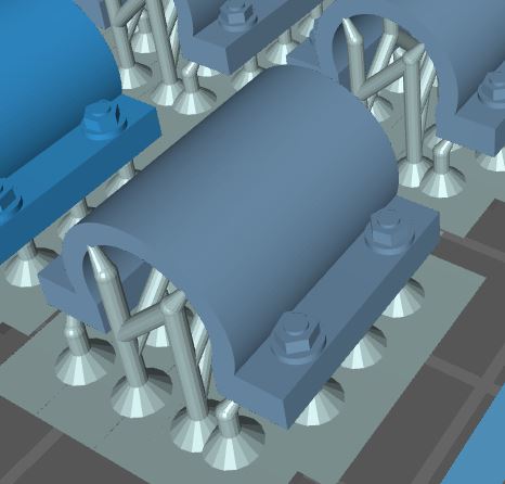
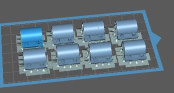
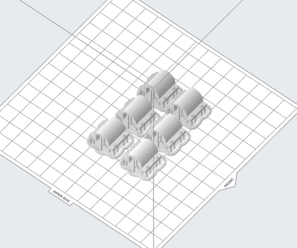
I then set this up on my FormLabs 2 3D printer see above and note the print area. At the lowest resolution the Elegoo beat the FormLabs by an hour on this print. This is because there are more operations going on on the FormLabs for each print layer.
However, who cares. Its the quality of print that matters.
MYLES- I printed thru the U Disk; After attaching the Elegoo USB port to my computer USB port my computer does not see the Elegoo? Is yours connected to the PC?
Alan
Attachments
Images (4)


Try this link: https://www.facebook.com/19642.../?type=3&theater
That's a terrific image. That was a 12 cylinder version, but a similar era. It has the outside the heads fuel distribution pipes that I've added. I don't know if I have enough head room to have the engine hanging above the engine. That's directly the result of the very large-girdered overhead crane that I chose to model. I think I'm going to draw the engine block as a bare block with open cylinders and access hatch openings. It could be neat to weather it and have it on cribbing outside.
The Elegoo, from what I understand, only gets fed by a thumb drive plugged into the port. I haven't tried to do it directly, nor do I intend to. I also found, strangely, that the Machine didn't recognize print files that I saved on the thumb drive's root directory. When I first turned it on and put my first file on the root, it couldn't find it. I thought there was an error. Then I found the Rook on a separate subdirectory and it found it and printed it perfectly. I moved my file to that sub-directory and it found mine too. I've got a sub-directory called "3D Prints" on both thumb drives I'm using and have no trouble with the Machine finding them.
Did some errands today so didn't do much, but what I did do seems to have found the limits on tiny prints. I grew four machines: the surface grinder - Came out okay, the metal band saw - All good except that I forgot to thicken the bottom plate of the chip pan and it basically doesn't have a bottom now, an acetylene welding set - really flimsy and the wheels are falling off even after I used Bondic to reinforce, and a Lincoln Electric MIG welding setup - this print was close to ridiculous.
Still having problems with hand wheels, but these almost worked except for the angled one. On the MIG Welder, one set of hoses actually is still there. The other was so fine that it couldn't hold itself together. Magnet wire would be better. Sometimes metal just is the better material. Even without the chip pan floor, I will use the saw as is, but correct the drawing for anyone else that wants this file. I do not recommend making the MIG welder. It's just too diminutive to be practical. I'm happy that I was able to correct most of the problems with the saw.

Then I printed some furniture. The cabinet and shelves worked fine. The work bench and shelves was almost a disaster. I had doubled the thickness of the legs and added some X-bracing, but I forgot to thicken the shelves. They came out paper thin. The first shelf barely printed at all. The legs were too flimsy. I need to make them square and add more triangulation to stiffen it all up and then it will work. Once again, things you get directly from the SketchUp 3D Warehouse don't work until you mess with them.

Right now I'm working on a floor drill press. The piece looked pretty good when I first examined it. Then I zoomed in closer and found that the knobs on the ends of the three handles were all reversed. So I fixed those. Then I looked at it bottom up and found that the drill press table was not a solid. The outer portions were solid, but the space between the bracing was unfilled. The whole table would have been a flop. I have to made the handles about 3X thicker than drawn or they won't work either. Upon even closer inspection I found that the circular area at the base of the knobs was open… no face. The knobs would have failed even though I got the faces correctly oriented. I had to zoom in very, very close to see this. The lime green from the insides of the ball caught my attention. I thought it was a reversed face, but then noticed there was no face at all and I was looking at the knob's interior.
I've said this before: 3D resin printing shifts the emphasis from crafting or making to evaluation, analysis and drawing.
Happy Labor Day Everyone! Be safe and have fun!
Attachments
Images (2)


The fine x-bracing could be a basis for scaffolding in a future print.
My first ELegoo print was no-good as one end bent upward coming off the support pins. Apparently I needed more support pins; However, the print clearly showed the small bolts on either side.
So I tried again with more supports but only one of the three printed. the other two printed FLAT on the tray surface. I had to clean the tray removing the pancake globs.
Ahh, the learning curve. . . .
Alan, place them at a 45 degree angle to minimize the adhesion forces on the FEP surface. When at all possible don't print large surfaces parallel to the platen. You're asking for trouble. I had a complete failure on the welding table. I went back and really looked at the drawing and found that the original artist had fully details scale casters including foot locks. I went back and solidified them and got rid of those ridiculous details would be invisible. I then found that the frame memnbers were drawn as hollow square steel tubing. While this is correct, it meant that the printer was creating part that were hollow with a wall thickness of maybe 0.001". No wonder everything before the table wasn't there. I've revised it completely and solidified everything. Rotate them so the widest surface is being held by most of the supports.
I just set this up on the slicer. I rotated them -135 degrees. I also didn't want a lot of supports in places where they were hard to remove. It's funny, but after hardening for four minutes, those spindly legs on that first workbench print are able to hold it up. Regardless, I beefed up the whole design and made the shelves solid.

Attachments
Images (1)

Alan,
Sounds like my first two prints, For a moment I thought you were commenting on my prints.
Gerry
Myles,
Printed a "concrete" foundation for mast mounted signals. My prints must need some your fertilizer they only grew to approx. half size. Maybe good for "HO" scale. Didn't have that problem with my first prints they were to size but were distorted in area closest to the build plate. The foundations prints have a little distortion in that same area.
I forgot to mention. The only unit of measure that the ChiTuBox slicer works with is millimeters. It will produce funny things if the STL units are in inches. That was the cause of my very first "microscopic" lathe print. It may be why you're getting funny dimensions. Checked what came out of the machine this morning and everything printed. Haven't unloaded them yet. And even with enlarging the drill press' lever arms on the down feed 2X, they're still awfully tiny.
Add Reply
Sign In To Reply
